EP0155496A2 - Emissionsplasmaquelle - Google Patents
Emissionsplasmaquelle Download PDFInfo
- Publication number
- EP0155496A2 EP0155496A2 EP85101457A EP85101457A EP0155496A2 EP 0155496 A2 EP0155496 A2 EP 0155496A2 EP 85101457 A EP85101457 A EP 85101457A EP 85101457 A EP85101457 A EP 85101457A EP 0155496 A2 EP0155496 A2 EP 0155496A2
- Authority
- EP
- European Patent Office
- Prior art keywords
- source
- series
- shunt
- variable
- variable impedance
- Prior art date
- Legal status (The legal status is an assumption and is not a legal conclusion. Google has not performed a legal analysis and makes no representation as to the accuracy of the status listed.)
- Granted
Links
Images

Classifications
-
- H—ELECTRICITY
- H05—ELECTRIC TECHNIQUES NOT OTHERWISE PROVIDED FOR
- H05H—PLASMA TECHNIQUE; PRODUCTION OF ACCELERATED ELECTRICALLY-CHARGED PARTICLES OR OF NEUTRONS; PRODUCTION OR ACCELERATION OF NEUTRAL MOLECULAR OR ATOMIC BEAMS
- H05H1/00—Generating plasma; Handling plasma
- H05H1/24—Generating plasma
- H05H1/26—Plasma torches
- H05H1/32—Plasma torches using an arc
- H05H1/34—Details, e.g. electrodes, nozzles
- H05H1/36—Circuit arrangements
-
- H—ELECTRICITY
- H05—ELECTRIC TECHNIQUES NOT OTHERWISE PROVIDED FOR
- H05H—PLASMA TECHNIQUE; PRODUCTION OF ACCELERATED ELECTRICALLY-CHARGED PARTICLES OR OF NEUTRONS; PRODUCTION OR ACCELERATION OF NEUTRAL MOLECULAR OR ATOMIC BEAMS
- H05H1/00—Generating plasma; Handling plasma
- H05H1/24—Generating plasma
- H05H1/26—Plasma torches
- H05H1/30—Plasma torches using applied electromagnetic fields, e.g. high frequency or microwave energy
Definitions
- the present invention generally relates to a plasma emission source and, in particular, relates to a source wherein the power transfer efficiency is continuously and automatically maximized.
- Plasma emission sources are used to atomize and excite a sample to cause the emission of light at wavelengths which are characteristic of the atomic structure of the sample.
- the emitted light is detected and measured by a spectrophotometer to complete the analytical process.
- radio-frequency (RF) energy is inductively coupled from an RF generator to a plasma torch.
- Liquid samples are mixed with a solvent, nebulized and delivered into the flame of the torch.
- the torch is an argon plasma discharge and the sample plus solvent is carried thereinto by a stream of argon.
- the efficiency of the energy transferred from the RF generator to the load is dependent on the impedance matching therebetween.
- modern plasma emission sources include an impedance matching network between the RF generator and the plasma torch.
- the impedance of the torch depends upon both the static and dynamic operating parameters of the plasma emission source.
- Some of the parameters affecting the impedance of the torch include: changes in the sample and/or solvent; the desired operating temperature of the torch and the efficiency of the nebulizer. To date such changes required the operator to manually fine tune the impedance matching network.
- the nebulizer flow adjustments were quite critical in order to help minimize the required manual tuning. Nevertheless, it is quite difficult to maintain the continuous maximum power transfer since these changes are usually dynamic and occur during the actual measuring time.
- plasma emission sources presently require excessive RF power input levels to compensate for the relatively poor power transfer to the torch and require frequent readjustment, particularly when solvents are changed.
- This object is accomplished, at least in part, by a plasma emission source having an impedance matching network which continuously and automatically matches the impedance between the RF generator and the plasma torch.
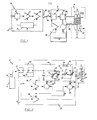
- a plasma emission source generally indicated at 10 in the drawings and embodying the principles of the present invention, includes an RF generator 12 an argon plasma torch 14 and an impedance matching network 16 therebetween.
- the RF generator 12 includes a crystal control oscillator 18 which provides RF energy to a RF driver 20.
- the driver 20 delivers RF power to an RF power amplifier 22 which preferably has a 50 ohm output impedance.
- the RF generator 12 is designed to supply between 200 to 2000 watts of RF power.
- the 50 ohm output is adapted to connect to a coaxial line 24.
- the oscillator 18, driver 20 and the power amplifier 22 are all driven via a DC power supply 26 which operates from rectified AC.
- the power supply 26 can either be a single unit with multiple outputs or can include more than one dedicated power supply.
- the argon plasma torch 14 includes an RF loading coil 28 surrounding a glass torch chamber 30.
- the glass torch chamber 30 in this embodiment includes an argon inlet 32 and a sample mixture inlet 34.
- the RF load coil 28 is 4 turns of 1/8 inch O.D. copper or stainless steel tubing and preferably has a low impedance.
- the RF generator 12 provides RF power to the load coil 28 of the plasma torch 14 via the impedance matching network 16. That is, the output 36 of the generator 12 is connected to the input 38 of the impedance matching network 16 and the output 40 of the impedance matching network 16 connects directly to the load coil 28.
- the impedance matching network 16 is shown in more detail, and includes a dual phase detector network 42, a variable impedance network 44 and a control unit 46.
- the dual phase detector network 42 is connected to the input 38 of the impedance matching network 16 and serially connected to the variable impedance network 44 which network 44 feeds the load coil 28.
- the phase detector network 42 includes a series phase detector 48 and a shunt phase detector 50.
- the series and shunt phase detectors, 48 and 50 respectively, are shown in the detailed schematic of Figure 3.
- the detector, 48 and 50 each include a pick-up coil, 52 and 54 respectively, which sense the phase of the voltage and phase of the current. If there is no phase difference then the coil 28 is exactly matched to the generator 12 and- maximum power transfer occurs.
- a phase change for example due to a change in an operating parameter, a signal is produced at the outputs, 56 and 58, of the series and shunt detectors, 48 and 50, respectively. These signals function as input signals to the control unit 46.
- the variable impedance network 44 includes a series capacitor network 60 and a shunt capacitor network 62.
- the series capacitor network 60 is serially connected between the dual phase detector network 42 and input of the load coil 28.
- the series capacitor network 60 includes a first branch 64 having a fixed capacitor 66 and a second branch 68 having two series variable capacitors, 70.
- the first and second branches, 64 and 68, respectively, are connected in parallel with each other.
- One side 72 of the shunt capacitor network 62 is connected between the dual phase detector network 42 and the series capacitor network 60.
- the other side 74 of the shunt capacitor network 62 is connected to ground in common with the output of the load coil 28.
- the shunt capacitor network 62 includes first and second variable capacitors, 76 and 78, connected in a parallel circuit.
- variable capacitor 70 of the series capacitor network 60 have a rated operating range from 5 to 50 picofarads whereas the variable capacitors, 76 and 78 have a rated operating range from 20 to 200 picofarads. It is also preferred that the variable capacitors, 70, 76 and 78 be of the air dielectric type such as those manufactured and marketed by Caywood Company of Maiden, Massachusetts.
- the control unit 46 includes a first motor 80 controlled by a servo amplifier 82 which servo amplifier 82 is connected to the output 56 of the series phase detector 48.
- the first motor 80 preferably a d.c. motor, drives the variable capacitors 70 via a gearbox 84.
- the control unit 46 also includes a second motor 86 controlled by a servo amplifier 88 which serve amplifier 88 is connected to the output 58 of the shunt phase detector 50.
- the second motor 86 drives the variable capacitors, 76 and 78, via a gearbox 90.
- the servo amplifiers 82 and 88 are arranged so that direction of the rotation of the motors, 80 and 86 respectively, is dependent upon the polarity of the signals at the outputs, 56 and 58 respectively. Hence, the motors, 80 and 86, are totally responsive to the series and shunt phase detectors, 48 and 50 respectively.
- the response of the variable impedance network 44 to impedance mismatching is continuous and automatic.
- the series and shunt phase detectors, 48 and 50 respectively, sample the RF voltage and the RF current. These two parameters sum in accordance with their phase relationship and, when rectified, produce DC voltages indicative of the impedance mismatch by virtue of the incident and reflective power passing through the impedance matching network 16.
- the incident power is maximum and the reflective power from the torch 14 is zero. If any mismatch occurs in the torch 14 due to changes in operating parameters or the change in nebulizer operating output the impedance across the coil 28 changes.
- the shunt phase detector 50 and the series phase detector 48 When-this occurs the shunt phase detector 50 and the series phase detector 48 due to the reflective power, activate the DC motors 86 and 80, respectively, which change the impedance value of the shunt capacitor network 62 and the series capacitor network 60 to reduce the reflective power to zero.
- the polarity of the signals from the phase detectors indicate which direction the respected DC motors are rotated in order to match the impedance.
- the maintenance of maximum power transfer from the RF generator 12 to the argon plasma torch 14 is fully automated and thereby eliminates and requirement for adjustment by means of a manual mechanism by an operator.
- the maximization of power transferred to the torch 14 eliminates reflective powers under all conditions and thus ensures maximum energy intensity from the plasma thereby resulting in a higher usable analytical signal to the spectrophotometer.
- the impedance matching network 16 exhibits the further advantage that, by use of air dielectric capacitors, the adjustment is more rapid than through the use of vacuum capacitors. Hence, the maximization of the response time reduces errors, due to dynamic operational conditions. Further, because the torch is always operating at maximum power transfer there is no need for complex manual readjustment of the impedance matching network when operating conditions change for example, from using an aqueous solvent to an organic solvent.
Landscapes
- Physics & Mathematics (AREA)
- Engineering & Computer Science (AREA)
- Plasma & Fusion (AREA)
- Spectroscopy & Molecular Physics (AREA)
- Electromagnetism (AREA)
- Investigating, Analyzing Materials By Fluorescence Or Luminescence (AREA)
- Plasma Technology (AREA)
Applications Claiming Priority (2)
| Application Number | Priority Date | Filing Date | Title |
|---|---|---|---|
| US06/585,807 US4629940A (en) | 1984-03-02 | 1984-03-02 | Plasma emission source |
| US585807 | 1984-03-02 |
Publications (3)
| Publication Number | Publication Date |
|---|---|
| EP0155496A2 true EP0155496A2 (de) | 1985-09-25 |
| EP0155496A3 EP0155496A3 (en) | 1987-09-09 |
| EP0155496B1 EP0155496B1 (de) | 1991-01-02 |
Family
ID=24343047
Family Applications (1)
| Application Number | Title | Priority Date | Filing Date |
|---|---|---|---|
| EP85101457A Expired EP0155496B1 (de) | 1984-03-02 | 1985-02-11 | Emissionsplasmaquelle |
Country Status (6)
| Country | Link |
|---|---|
| US (1) | US4629940A (de) |
| EP (1) | EP0155496B1 (de) |
| JP (2) | JPS60205241A (de) |
| AU (1) | AU3943185A (de) |
| CA (1) | CA1245729A (de) |
| DE (1) | DE3580991D1 (de) |
Cited By (9)
| Publication number | Priority date | Publication date | Assignee | Title |
|---|---|---|---|---|
| WO1988007273A1 (en) * | 1987-03-20 | 1988-09-22 | Hughes Aircraft Company | Pumping system for rf excited gas devices |
| US5082517A (en) * | 1990-08-23 | 1992-01-21 | Texas Instruments Incorporated | Plasma density controller for semiconductor device processing equipment |
| GB2249893A (en) * | 1990-11-03 | 1992-05-20 | Grau Ltd | Automatic electronic control system impedance matching circuit |
| EP0568920A1 (de) * | 1992-05-07 | 1993-11-10 | The Perkin-Elmer Corporation | Induktiv gekoppelte Plasmaquelle |
| EP0602764A1 (de) * | 1992-12-17 | 1994-06-22 | FISONS plc | Induktiv gekoppelte Plasmaspektrometer und Radiofrequenzleistungsgenerator dafür |
| EP0614210A1 (de) * | 1993-03-05 | 1994-09-07 | Varian Australia Pty. Ltd. | Plasma-Massenspektrometrie |
| US5477089A (en) * | 1990-11-03 | 1995-12-19 | Grau Limited | Automotive electronic control systems |
| US6958063B1 (en) | 1999-04-22 | 2005-10-25 | Soring Gmbh Medizintechnik | Plasma generator for radio frequency surgery |
| WO2012159620A3 (de) * | 2011-05-24 | 2013-03-07 | Hüttinger Elektronik Gmbh + Co. Kg | Verfahren zur impedanzanpassung der ausgangsimpedanz einer hochfrequenzleistungsversorgungsanordnung an die impedanz einer plasmalast und hochfrequenzleistungsversorgungsanordnung |
Families Citing this family (59)
| Publication number | Priority date | Publication date | Assignee | Title |
|---|---|---|---|---|
| AT388814B (de) * | 1985-11-15 | 1989-09-11 | Paar Anton Kg | Verfahren und vorrichtung zum erzeugen eines hf-induzierten edelgasplasmas |
| US4833322A (en) * | 1986-05-02 | 1989-05-23 | Shell Oil Company | Method and apparatus for analysis of material |
| US4795880A (en) * | 1986-09-11 | 1989-01-03 | Hayes James A | Low pressure chemical vapor deposition furnace plasma clean apparatus |
| JPS63135799U (de) * | 1987-02-27 | 1988-09-06 | ||
| US4766287A (en) * | 1987-03-06 | 1988-08-23 | The Perkin-Elmer Corporation | Inductively coupled plasma torch with adjustable sample injector |
| US4956582A (en) * | 1988-04-19 | 1990-09-11 | The Boeing Company | Low temperature plasma generator with minimal RF emissions |
| US5155547A (en) * | 1990-02-26 | 1992-10-13 | Leco Corporation | Power control circuit for inductively coupled plasma atomic emission spectroscopy |
| US5383019A (en) * | 1990-03-23 | 1995-01-17 | Fisons Plc | Inductively coupled plasma spectrometers and radio-frequency power supply therefor |
| NL9000809A (nl) * | 1990-04-06 | 1991-11-01 | Philips Nv | Plasmagenerator. |
| DE4019729A1 (de) * | 1990-06-21 | 1992-01-02 | Leybold Ag | Ionenquelle |
| US5195045A (en) * | 1991-02-27 | 1993-03-16 | Astec America, Inc. | Automatic impedance matching apparatus and method |
| US5288971A (en) * | 1991-08-09 | 1994-02-22 | Advanced Energy Industries, Inc. | System for igniting a plasma for thin film processing |
| US5144206A (en) * | 1991-09-10 | 1992-09-01 | Gte Products Corporation | Electrodeless HID lamp coupling structure with integral matching network |
| US5187457A (en) * | 1991-09-12 | 1993-02-16 | Eni Div. Of Astec America, Inc. | Harmonic and subharmonic filter |
| US5175472A (en) * | 1991-12-30 | 1992-12-29 | Comdel, Inc. | Power monitor of RF plasma |
| US5216330A (en) * | 1992-01-14 | 1993-06-01 | Honeywell Inc. | Ion beam gun |
| US5280154A (en) * | 1992-01-30 | 1994-01-18 | International Business Machines Corporation | Radio frequency induction plasma processing system utilizing a uniform field coil |
| US5523955A (en) * | 1992-03-19 | 1996-06-04 | Advanced Energy Industries, Inc. | System for characterizing AC properties of a processing plasma |
| WO1993021685A1 (en) * | 1992-04-16 | 1993-10-28 | Advanced Energy Industries, Inc. | Stabilizer for switch-mode powered rf plasma processing |
| US5815047A (en) * | 1993-10-29 | 1998-09-29 | Applied Materials, Inc. | Fast transition RF impedance matching network for plasma reactor ignition |
| JPH07191764A (ja) * | 1993-12-27 | 1995-07-28 | Fujitsu Ltd | 高周波電源装置及びプラズマ発生装置 |
| JPH07282771A (ja) * | 1995-02-08 | 1995-10-27 | Yokogawa Electric Corp | 高周波誘導結合プラズマ分析計のプラズマ点火方法 |
| US5712592A (en) * | 1995-03-06 | 1998-01-27 | Applied Materials, Inc. | RF plasma power supply combining technique for increased stability |
| US5977715A (en) * | 1995-12-14 | 1999-11-02 | The Boeing Company | Handheld atmospheric pressure glow discharge plasma source |
| US5689215A (en) * | 1996-05-23 | 1997-11-18 | Lam Research Corporation | Method of and apparatus for controlling reactive impedances of a matching network connected between an RF source and an RF plasma processor |
| US5770922A (en) | 1996-07-22 | 1998-06-23 | Eni Technologies, Inc. | Baseband V-I probe |
| US6329757B1 (en) | 1996-12-31 | 2001-12-11 | The Perkin-Elmer Corporation | High frequency transistor oscillator system |
| GB9708268D0 (en) | 1997-04-24 | 1997-06-18 | Gyrus Medical Ltd | An electrosurgical instrument |
| DE19737244A1 (de) * | 1997-08-27 | 1999-03-04 | Harald Tobies | Vorrichtung und Verfahren zur Regelung der Phasenlage von Hochfrequenzelektroden bei Plasmaprozessen |
| EP1023819A4 (de) | 1997-10-14 | 2007-10-17 | Advanced Energy Ind Inc | System zur plasmazündung durch schnellen spannungsanstieg |
| US6449568B1 (en) | 1998-02-27 | 2002-09-10 | Eni Technology, Inc. | Voltage-current sensor with high matching directivity |
| CN1241316C (zh) | 1999-07-13 | 2006-02-08 | 东京电子株式会社 | 产生感性耦合的等离子的射频电源 |
| US6507155B1 (en) * | 2000-04-06 | 2003-01-14 | Applied Materials Inc. | Inductively coupled plasma source with controllable power deposition |
| US6472822B1 (en) * | 2000-04-28 | 2002-10-29 | Applied Materials, Inc. | Pulsed RF power delivery for plasma processing |
| US7106438B2 (en) * | 2002-12-12 | 2006-09-12 | Perkinelmer Las, Inc. | ICP-OES and ICP-MS induction current |
| US7511246B2 (en) | 2002-12-12 | 2009-03-31 | Perkinelmer Las Inc. | Induction device for generating a plasma |
| US6995545B2 (en) * | 2003-08-18 | 2006-02-07 | Mks Instruments, Inc. | Control system for a sputtering system |
| US7042311B1 (en) * | 2003-10-10 | 2006-05-09 | Novellus Systems, Inc. | RF delivery configuration in a plasma processing system |
| DE102004015090A1 (de) | 2004-03-25 | 2005-11-03 | Hüttinger Elektronik Gmbh + Co. Kg | Bogenentladungserkennungseinrichtung |
| WO2006099190A2 (en) * | 2005-03-11 | 2006-09-21 | Perkinelmer, Inc. | Plasmas and methods of using them |
| US8622735B2 (en) * | 2005-06-17 | 2014-01-07 | Perkinelmer Health Sciences, Inc. | Boost devices and methods of using them |
| US7742167B2 (en) * | 2005-06-17 | 2010-06-22 | Perkinelmer Health Sciences, Inc. | Optical emission device with boost device |
| US7459899B2 (en) | 2005-11-21 | 2008-12-02 | Thermo Fisher Scientific Inc. | Inductively-coupled RF power source |
| JP4586737B2 (ja) * | 2006-02-02 | 2010-11-24 | 株式会社島津製作所 | Icp分析装置 |
| DE502006005363D1 (de) * | 2006-11-23 | 2009-12-24 | Huettinger Elektronik Gmbh | Verfahren zum Erkennen einer Bogenentladung in einem Plasmaprozess und Bogenentladungserkennungsvorrichtung |
| US7795817B2 (en) * | 2006-11-24 | 2010-09-14 | Huettinger Elektronik Gmbh + Co. Kg | Controlled plasma power supply |
| EP1928009B1 (de) * | 2006-11-28 | 2013-04-10 | HÜTTINGER Elektronik GmbH + Co. KG | Bogenentladungs-Erkennungseinrichtung, Plasma-Leistungsversorgung und Verfahren zum Erkennen von Bogenentladungen |
| DE502006009308D1 (de) * | 2006-12-14 | 2011-05-26 | Huettinger Elektronik Gmbh | Bogenentladungs-Erkennungseinrichtung, Plasma-Leistungsversorgung und Verfahren zum Erkennen von Bogenentladungen |
| JP2011521735A (ja) | 2008-05-30 | 2011-07-28 | コロラド ステート ユニバーシティ リサーチ ファンデーション | プラズマを発生させるためのシステム、方法、および装置 |
| US8994270B2 (en) | 2008-05-30 | 2015-03-31 | Colorado State University Research Foundation | System and methods for plasma application |
| WO2009146432A1 (en) | 2008-05-30 | 2009-12-03 | Colorado State University Research Foundation | Plasma-based chemical source device and method of use thereof |
| US8659335B2 (en) * | 2009-06-25 | 2014-02-25 | Mks Instruments, Inc. | Method and system for controlling radio frequency power |
| US8222822B2 (en) | 2009-10-27 | 2012-07-17 | Tyco Healthcare Group Lp | Inductively-coupled plasma device |
| JP2013529352A (ja) | 2010-03-31 | 2013-07-18 | コロラド ステート ユニバーシティー リサーチ ファウンデーション | 液体−気体界面プラズマデバイス |
| EP2552340A4 (de) | 2010-03-31 | 2015-10-14 | Univ Colorado State Res Found | Plasmavorrichtung mit flüssig-gas-schnittstelle |
| WO2013046495A1 (ja) * | 2011-09-30 | 2013-04-04 | パナソニック株式会社 | 大気圧プラズマ発生装置及び大気圧プラズマ発生方法 |
| US9259798B2 (en) | 2012-07-13 | 2016-02-16 | Perkinelmer Health Sciences, Inc. | Torches and methods of using them |
| US9532826B2 (en) | 2013-03-06 | 2017-01-03 | Covidien Lp | System and method for sinus surgery |
| US9555145B2 (en) | 2013-03-13 | 2017-01-31 | Covidien Lp | System and method for biofilm remediation |
Family Cites Families (12)
| Publication number | Priority date | Publication date | Assignee | Title |
|---|---|---|---|---|
| US2745067A (en) * | 1951-06-28 | 1956-05-08 | True Virgil | Automatic impedance matching apparatus |
| US2742618A (en) * | 1951-12-29 | 1956-04-17 | Collins Radio Co | Phasing and magnitude adjusting circuit |
| FR1207566A (fr) * | 1958-06-26 | 1960-02-17 | Trt Telecom Radio Electr | Perfectionnements aux dispositifs d'accord automatique sur une charge largement variable |
| US3132313A (en) * | 1959-08-13 | 1964-05-05 | Alford Andrew | Impedance matching filter |
| US3366883A (en) * | 1965-12-20 | 1968-01-30 | Avco Corp | Automatic broad band vswr power control |
| US3958883A (en) * | 1974-07-10 | 1976-05-25 | Baird-Atomic, Inc. | Radio frequency induced plasma excitation of optical emission spectroscopic samples |
| US4207137A (en) * | 1979-04-13 | 1980-06-10 | Bell Telephone Laboratories, Incorporated | Method of controlling a plasma etching process by monitoring the impedance changes of the RF power |
| US4373581A (en) * | 1981-01-19 | 1983-02-15 | Halliburton Company | Apparatus and method for radio frequency heating of hydrocarbonaceous earth formations including an impedance matching technique |
| US4356458A (en) * | 1981-08-31 | 1982-10-26 | Harry H. Leveen | Automatic impedance matching apparatus |
| JPS58135600A (ja) * | 1982-02-08 | 1983-08-12 | 株式会社日立国際電気 | プラズマ励起用高周波電力供給装置 |
| JPS58169051A (ja) * | 1982-03-31 | 1983-10-05 | Shimadzu Corp | 誘導結合プラズマ光源用電源装置 |
| US4482246A (en) * | 1982-09-20 | 1984-11-13 | Meyer Gerhard A | Inductively coupled plasma discharge in flowing non-argon gas at atmospheric pressure for spectrochemical analysis |
-
1984
- 1984-03-02 US US06/585,807 patent/US4629940A/en not_active Expired - Lifetime
-
1985
- 1985-01-23 CA CA000472670A patent/CA1245729A/en not_active Expired
- 1985-02-11 EP EP85101457A patent/EP0155496B1/de not_active Expired
- 1985-02-11 DE DE8585101457T patent/DE3580991D1/de not_active Expired - Lifetime
- 1985-02-28 JP JP60037815A patent/JPS60205241A/ja active Pending
- 1985-03-01 AU AU39431/85A patent/AU3943185A/en not_active Abandoned
-
1993
- 1993-11-17 JP JP1993061890U patent/JPH0734363Y2/ja not_active Expired - Lifetime
Cited By (12)
| Publication number | Priority date | Publication date | Assignee | Title |
|---|---|---|---|---|
| WO1988007273A1 (en) * | 1987-03-20 | 1988-09-22 | Hughes Aircraft Company | Pumping system for rf excited gas devices |
| US5082517A (en) * | 1990-08-23 | 1992-01-21 | Texas Instruments Incorporated | Plasma density controller for semiconductor device processing equipment |
| GB2249893A (en) * | 1990-11-03 | 1992-05-20 | Grau Ltd | Automatic electronic control system impedance matching circuit |
| GB2249893B (en) * | 1990-11-03 | 1994-09-14 | Grau Ltd | Automotive electronic control systems |
| US5477089A (en) * | 1990-11-03 | 1995-12-19 | Grau Limited | Automotive electronic control systems |
| EP0568920A1 (de) * | 1992-05-07 | 1993-11-10 | The Perkin-Elmer Corporation | Induktiv gekoppelte Plasmaquelle |
| EP0602764A1 (de) * | 1992-12-17 | 1994-06-22 | FISONS plc | Induktiv gekoppelte Plasmaspektrometer und Radiofrequenzleistungsgenerator dafür |
| EP0614210A1 (de) * | 1993-03-05 | 1994-09-07 | Varian Australia Pty. Ltd. | Plasma-Massenspektrometrie |
| US5519215A (en) * | 1993-03-05 | 1996-05-21 | Anderson; Stephen E. | Plasma mass spectrometry |
| US6958063B1 (en) | 1999-04-22 | 2005-10-25 | Soring Gmbh Medizintechnik | Plasma generator for radio frequency surgery |
| WO2012159620A3 (de) * | 2011-05-24 | 2013-03-07 | Hüttinger Elektronik Gmbh + Co. Kg | Verfahren zur impedanzanpassung der ausgangsimpedanz einer hochfrequenzleistungsversorgungsanordnung an die impedanz einer plasmalast und hochfrequenzleistungsversorgungsanordnung |
| US9111718B2 (en) | 2011-05-24 | 2015-08-18 | Trumpf Huettinger Gmbh + Co. Kg | Method for matching the impedance of the output impedance of a high-frequency power supply arrangement to the impedance of a plasma load and high-frequency power supply arrangement |
Also Published As
| Publication number | Publication date |
|---|---|
| JPH0734363Y2 (ja) | 1995-08-02 |
| JPH0646359U (ja) | 1994-06-24 |
| US4629940A (en) | 1986-12-16 |
| EP0155496A3 (en) | 1987-09-09 |
| AU3943185A (en) | 1985-09-05 |
| EP0155496B1 (de) | 1991-01-02 |
| CA1245729A (en) | 1988-11-29 |
| DE3580991D1 (de) | 1991-02-07 |
| JPS60205241A (ja) | 1985-10-16 |
Similar Documents
| Publication | Publication Date | Title |
|---|---|---|
| US4629940A (en) | Plasma emission source | |
| US3958883A (en) | Radio frequency induced plasma excitation of optical emission spectroscopic samples | |
| US4877999A (en) | Method and apparatus for producing an hf-induced noble-gas plasma | |
| US6329757B1 (en) | High frequency transistor oscillator system | |
| EP0568920B1 (de) | Induktiv gekoppelte Plasmaquelle | |
| US5793162A (en) | Apparatus for controlling matching network of a vacuum plasma processor and memory for same | |
| US4557819A (en) | System for igniting and controlling a wafer processing plasma | |
| US5155547A (en) | Power control circuit for inductively coupled plasma atomic emission spectroscopy | |
| US6424232B1 (en) | Method and apparatus for matching a variable load impedance with an RF power generator impedance | |
| US6677711B2 (en) | Plasma processor method and apparatus | |
| US5654679A (en) | Apparatus for matching a variable load impedance with an RF power generator impedance | |
| US5936481A (en) | System for impedance matching and power control for apparatus for high frequency plasma treatment | |
| EP0752757A1 (de) | RF-Anpassung Detektorschaltung mit doppeltem Richtkoppler | |
| EP0602764A1 (de) | Induktiv gekoppelte Plasmaspektrometer und Radiofrequenzleistungsgenerator dafür | |
| US4256404A (en) | Optoelectronic feedback control for a spectrometer | |
| EP0734049B1 (de) | Verfahren und Vorrichtung zur Plasmamassenspektrometrie | |
| US3917407A (en) | Spectrophotometer with automatically fine tuned monochromator | |
| US3171882A (en) | Spectroscopic apparatus | |
| Montaser et al. | Versatile impedance matching network for inductively coupled plasma spectrometry | |
| EP0122403A1 (de) | Plasma-Anregungssystem | |
| EP0312613B1 (de) | Laser-oszillator | |
| CN1314191C (zh) | 带有功率控制的电感耦合等离子体自激式射频发生器 | |
| CN113267486A (zh) | 一种宽谱段高分辨电感耦合等离子体发射光谱仪 | |
| JPH07282771A (ja) | 高周波誘導結合プラズマ分析計のプラズマ点火方法 | |
| Smith Jr et al. | Consideration in the design of a sample introduction and plasma generation system for ICP spectroscopy |
Legal Events
| Date | Code | Title | Description |
|---|---|---|---|
| PUAI | Public reference made under article 153(3) epc to a published international application that has entered the european phase |
Free format text: ORIGINAL CODE: 0009012 |
|
| AK | Designated contracting states |
Designated state(s): DE FR GB IT |
|
| PUAL | Search report despatched |
Free format text: ORIGINAL CODE: 0009013 |
|
| AK | Designated contracting states |
Kind code of ref document: A3 Designated state(s): DE FR GB IT |
|
| 17P | Request for examination filed |
Effective date: 19880309 |
|
| 17Q | First examination report despatched |
Effective date: 19890524 |
|
| GRAA | (expected) grant |
Free format text: ORIGINAL CODE: 0009210 |
|
| AK | Designated contracting states |
Kind code of ref document: B1 Designated state(s): DE FR GB IT |
|
| ITF | It: translation for a ep patent filed | ||
| REF | Corresponds to: |
Ref document number: 3580991 Country of ref document: DE Date of ref document: 19910207 |
|
| ET | Fr: translation filed | ||
| PLBE | No opposition filed within time limit |
Free format text: ORIGINAL CODE: 0009261 |
|
| STAA | Information on the status of an ep patent application or granted ep patent |
Free format text: STATUS: NO OPPOSITION FILED WITHIN TIME LIMIT |
|
| 26N | No opposition filed | ||
| REG | Reference to a national code |
Ref country code: GB Ref legal event code: 732E |
|
| PGFP | Annual fee paid to national office [announced via postgrant information from national office to epo] |
Ref country code: FR Payment date: 20010117 Year of fee payment: 17 |
|
| PGFP | Annual fee paid to national office [announced via postgrant information from national office to epo] |
Ref country code: GB Payment date: 20010118 Year of fee payment: 17 Ref country code: DE Payment date: 20010118 Year of fee payment: 17 |
|
| REG | Reference to a national code |
Ref country code: GB Ref legal event code: IF02 |
|
| PG25 | Lapsed in a contracting state [announced via postgrant information from national office to epo] |
Ref country code: GB Free format text: LAPSE BECAUSE OF NON-PAYMENT OF DUE FEES Effective date: 20020211 |
|
| PG25 | Lapsed in a contracting state [announced via postgrant information from national office to epo] |
Ref country code: DE Free format text: LAPSE BECAUSE OF NON-PAYMENT OF DUE FEES Effective date: 20020903 |
|
| GBPC | Gb: european patent ceased through non-payment of renewal fee |
Effective date: 20020211 |
|
| PG25 | Lapsed in a contracting state [announced via postgrant information from national office to epo] |
Ref country code: FR Free format text: LAPSE BECAUSE OF NON-PAYMENT OF DUE FEES Effective date: 20021031 |
|
| REG | Reference to a national code |
Ref country code: FR Ref legal event code: ST |