EP0155869A1 - Anlage zur Gewinnung von Mineralien vom Meeresboden - Google Patents
Anlage zur Gewinnung von Mineralien vom Meeresboden Download PDFInfo
- Publication number
- EP0155869A1 EP0155869A1 EP85400311A EP85400311A EP0155869A1 EP 0155869 A1 EP0155869 A1 EP 0155869A1 EP 85400311 A EP85400311 A EP 85400311A EP 85400311 A EP85400311 A EP 85400311A EP 0155869 A1 EP0155869 A1 EP 0155869A1
- Authority
- EP
- European Patent Office
- Prior art keywords
- ore
- relay block
- installation according
- ship
- station
- Prior art date
- Legal status (The legal status is an assumption and is not a legal conclusion. Google has not performed a legal analysis and makes no representation as to the accuracy of the status listed.)
- Withdrawn
Links
- 238000009434 installation Methods 0.000 title claims abstract description 33
- 238000000605 extraction Methods 0.000 title claims description 7
- 229910052500 inorganic mineral Inorganic materials 0.000 title claims description 5
- 239000011707 mineral Substances 0.000 title claims description 5
- 238000005406 washing Methods 0.000 claims abstract description 14
- XLYOFNOQVPJJNP-UHFFFAOYSA-N water Substances O XLYOFNOQVPJJNP-UHFFFAOYSA-N 0.000 claims abstract description 14
- 230000000694 effects Effects 0.000 claims abstract description 7
- 239000013049 sediment Substances 0.000 claims description 4
- 238000012544 monitoring process Methods 0.000 claims description 3
- 239000003380 propellant Substances 0.000 claims description 3
- 230000005484 gravity Effects 0.000 claims description 2
- 238000005086 pumping Methods 0.000 claims description 2
- 238000011084 recovery Methods 0.000 claims description 2
- 239000003381 stabilizer Substances 0.000 claims description 2
- 239000000203 mixture Substances 0.000 description 7
- 239000013535 sea water Substances 0.000 description 4
- XEEYBQQBJWHFJM-UHFFFAOYSA-N Iron Chemical compound [Fe] XEEYBQQBJWHFJM-UHFFFAOYSA-N 0.000 description 2
- PXHVJJICTQNCMI-UHFFFAOYSA-N Nickel Chemical compound [Ni] PXHVJJICTQNCMI-UHFFFAOYSA-N 0.000 description 2
- 230000005611 electricity Effects 0.000 description 2
- 229910052751 metal Inorganic materials 0.000 description 2
- 239000002184 metal Substances 0.000 description 2
- RYGMFSIKBFXOCR-UHFFFAOYSA-N Copper Chemical compound [Cu] RYGMFSIKBFXOCR-UHFFFAOYSA-N 0.000 description 1
- PWHULOQIROXLJO-UHFFFAOYSA-N Manganese Chemical compound [Mn] PWHULOQIROXLJO-UHFFFAOYSA-N 0.000 description 1
- ZOKXTWBITQBERF-UHFFFAOYSA-N Molybdenum Chemical compound [Mo] ZOKXTWBITQBERF-UHFFFAOYSA-N 0.000 description 1
- 230000005540 biological transmission Effects 0.000 description 1
- 239000000969 carrier Substances 0.000 description 1
- 238000004140 cleaning Methods 0.000 description 1
- 239000010941 cobalt Substances 0.000 description 1
- 229910017052 cobalt Inorganic materials 0.000 description 1
- GUTLYIVDDKVIGB-UHFFFAOYSA-N cobalt atom Chemical compound [Co] GUTLYIVDDKVIGB-UHFFFAOYSA-N 0.000 description 1
- 239000002131 composite material Substances 0.000 description 1
- 229910052802 copper Inorganic materials 0.000 description 1
- 239000010949 copper Substances 0.000 description 1
- 238000001514 detection method Methods 0.000 description 1
- 238000007667 floating Methods 0.000 description 1
- 239000006260 foam Substances 0.000 description 1
- 229910052742 iron Inorganic materials 0.000 description 1
- 229910052748 manganese Inorganic materials 0.000 description 1
- 239000011572 manganese Substances 0.000 description 1
- 150000002739 metals Chemical class 0.000 description 1
- 238000000034 method Methods 0.000 description 1
- 238000005065 mining Methods 0.000 description 1
- 238000012986 modification Methods 0.000 description 1
- 230000004048 modification Effects 0.000 description 1
- 229910052750 molybdenum Inorganic materials 0.000 description 1
- 239000011733 molybdenum Substances 0.000 description 1
- 229910052759 nickel Inorganic materials 0.000 description 1
- 230000003071 parasitic effect Effects 0.000 description 1
- 239000011435 rock Substances 0.000 description 1
- 238000009991 scouring Methods 0.000 description 1
- 239000002689 soil Substances 0.000 description 1
- 239000004575 stone Substances 0.000 description 1
Images


Classifications
-
- E—FIXED CONSTRUCTIONS
- E02—HYDRAULIC ENGINEERING; FOUNDATIONS; SOIL SHIFTING
- E02F—DREDGING; SOIL-SHIFTING
- E02F7/00—Equipment for conveying or separating excavated material
- E02F7/005—Equipment for conveying or separating excavated material conveying material from the underwater bottom
-
- E—FIXED CONSTRUCTIONS
- E02—HYDRAULIC ENGINEERING; FOUNDATIONS; SOIL SHIFTING
- E02F—DREDGING; SOIL-SHIFTING
- E02F3/00—Dredgers; Soil-shifting machines
- E02F3/04—Dredgers; Soil-shifting machines mechanically-driven
- E02F3/88—Dredgers; Soil-shifting machines mechanically-driven with arrangements acting by a sucking or forcing effect, e.g. suction dredgers
- E02F3/8858—Submerged units
-
- E—FIXED CONSTRUCTIONS
- E21—EARTH OR ROCK DRILLING; MINING
- E21C—MINING OR QUARRYING
- E21C50/00—Obtaining minerals from underwater, not otherwise provided for
Definitions
- the present invention relates generally to an installation for the exploitation and extraction of large quantities of ores, for example polymetallic nodules present on the seabed.
- Installations are also known which use devices capable of moving on the seabed and equipped with means for collecting and storing nodules. These machines can be towed by a cable from the surface or be self-propelled and programmed beforehand to operate on the seabed. Some of them having their own source of energy can also be produced so as to ensure not only the removal of the nodules but also their ascent to the surface.
- the present invention relates precisely to an installation for extracting ores from the seabed at a great depth, which notably makes it possible to significantly improve the operating yield of a deposit and to provide the flexibility of use necessary depending on operating conditions.
- the intermediate submarine station submerged at a certain depth below the water level so as to be constantly sheltered from swell includes autonomous means for keeping the relay unit and the vehicles in operation and to ensure the recovery and storage of the ore in the event of disconnection of the link with the surface vessel.
- the installation for mining and collecting ore on the seabed at a great depth shown in Figure 1, consists of a ship 1 floating on the surface of the water, and several vehicles 50 for collecting ore, moving on the seabed 2 for example at 5500 meters below sea level.
- the link between ship 1 and vehicles 50, for the supply of energy and the raising of the ore is performed as follows. First of all the ship 1 is connected by a flexible pipe 3 to an underwater station 20 submerged at a depth of the order of 300 to 350 meters, which itself supports by a rigid pipe 4 a relay block 30 submerged at a depth of about 4,500 to 5,000 meters.
- Each vehicle 50 is connected to the relay block 30 by a set of cables and pipes 5 ensuring on the one hand the transmission of energy and the control of the commands and on the other hand the ascent of the ore to the relay block 30.
- These cables and pipes 5 are held by floats 6 so as not to transmit parasitic forces to vehicles 50.
- the vessel 1 constituting the base of life supplies the energy to the various motors and pumps necessary for the operation of the entire installation and ensures the storage of the ore collected between two rotations of the ore carriers.
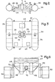
- the intermediate submarine station 20 shown in more detail in Figures 2 and 3, is located about 300-350 meters below the water level, in order to be sheltered from the effects of the swell . It mainly comprises an apron 21 on which are mounted a connection box 22 between the flexible pipe 3 and the rigid pipe 4, and several primary pumps 23 capable of pumping the mixture of ores and seawater from the relay block 30 by line 4 and driving this mixture to the surface ship 1 via line 3.
- a longitudinal float 24 is mounted on each side of the deck 21 to maintain the station at altitude; these floats can possibly serve as buffer storage of the ore, for an operation of about ten hours, or for example 3000 m 3 per float, in particular in the event of disconnection of the link with the ship, as will be seen later.
- each float is connected by a pipe 25 to the connection box, Z ment 22.
- This underwater station 20 also includes a system of longitudinal and vertical thrusters 26 for maintaining it in heading and altitude, as well as a control system 27 receiving orders from the ship and control of the pumps 23 and thrusters 26.
- L electricity necessary for the operation of the station is supplied by ship 1, but in the event of disconnection of the link with said ship, one or more standby generator sets 28 mounted on the bulkhead 21 supply the electricity necessary.
- the relay block 30 located at 4500-5000 meters below the water level, is attached to the underwater station 20 via the ascent pipe 4 and cables not shown. It mainly includes everything that is not essential on 50 vehicles in order to limit the energy to be brought to the bare minimum.
- This relay block ( Figures 4 and 5) includes a platform 31 supporting a silo 32 to allow among other things a buffer storage of approximately 500 tonnes of ore between the vehicles 50 and the station 20.
- On this platform are also mounted hydraulic groups 33 with sea water and a monitoring and control system 34.
- the hydraulic groups 33 supplying pressurized water to actuate the hydraulic motors of vehicles 50, are powered by electric motors 35 receiving the energy of the ship through the submarine station 20.
- the control system 34 is capable on the one hand, of carrying out a certain number of pre-programmed tasks and, on the other hand, of carrying out the orders given from the ship according to the elements transmitted to the latter.
- the silo 32 has multiple tangential entrances 36 at its upper part to form a vortex; these inlets each communicate via a pump 37 with a pipe 5 for the ascent of the ore into the silo from a vehicle 50. Each inlet 36 is therefore connected to a vehicle which allows the ascent of the ore to from several vehicles simultaneously.
- a grid 38 in the shape of a cone directed downwards, so as to effect the sorting and final washing of the ore by gravity.
- the upper pipe 4 for raising the ore to the ship by the station 20 enters the interior of the silo 32 and emerges above the grid 38.
- said block relay comprises propellants 39 as well as vertical stabilizers 40 arranged on each side of the silo 32.
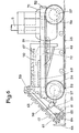
- the collection of the underwater ore is carried out by the vehicles 50 (FIGS. 6, 7 and 8) which mainly consist of a carrying chassis, a propulsion system, a ore collection, and an ore washing and processing system.
- the chassis 51 consisting of metal beams 52 internally lined with foam supports the various elements of the vehicle and in particular the propulsion system 53.
- This propulsion system 53 is formed by example by a pair of tracks 54 and 55 located on each side of the chassis 51.
- Each track (54-55) is driven by wheels 56 which are themselves driven by hydraulic motors 57 housed in the rim.
- the pressurized water for the hydraulic motors 57 is supplied by the hydraulic groups 33 of the relay block 30.
- Each wheel 56 is driven by a hydraulic motor 57 so as to ensure high mobility of the vehicle.
- the tracks (54, 55) in mixed metallic and composite structure, are provided with notches internally for the connection with the wheels 56 and externally to ensure a grip on the ground.
- the ore collection system which consists of two trains of bucket chains 58 arranged in line so as to cover a sufficient width.
- Each train of bucket chains 58 is independent and can pivot around an axis 59 located at the top. This pivoting is controlled by a jack 60 and makes it possible to adapt each train to the configuration of the ground.
- the endless chains 61, support of the buckets, pass on wheels 62 mounted on arms (63-64), connected to one another in an elastic manner, for example by springs 65, so that when a bucket hits an obstacle (large stone, rock), the lower arm 64 is raised and the bucket passes over the obstacle instead of bracing on it.
- the buckets are also protected by bumpers 66.
- the buckets pour their collection into a treatment and washing system comprising two conveyor belts (67-68) superimposed and made up of a mesh with calibrated mesh for the selection of nodules.
- the excessively large nodules as well as the sediments are evacuated in a hopper 69.
- a first washing is. provided by ramps 70 located above the carpet 67.
- the nodules thus selected are then transported in a tank 71, using a screw 72 in which they are rid of the gangue which may remain and where they undergo a second wash.
- the tank 71 is connected to the pipe 5 for raising the nodules to the relay block 30.
- Each vehicle 50 is of course equipped with an underwater observation device, a detection device or an acoustic display system, in order to ensure safe and easy operating conditions, even in the case where the water is cloudy and where visibility is reduced.
- the ore pickup facility operates as follows.
- the assembly - submarine station 20 and relay block 30 connected to said station by line 4 is maintained, thanks to the thrusters 26 and possibly ballasts, in a position such that station 20 is located approximately 300-350 meters below the water level.
- This assembly can also evolve according to the orders given from the ship 1.
- the personnel on the ship controls the operation of the installation and can intervene at any time.
- the energy necessary for the operation of the installation and in particular of the various elements of the vehicles 50 is supplied by the ship 1 and the pressurized water for the propulsion of the said vehicles is supplied by the hydraulic groups 33 of the relay block 30
- the vehicles 50 therefore move on the bottom 2 and pick up the ore.
- the two trains of bucket chains 58 pour their collection onto the upper belt 67 where a first washing is carried out by the ramps 70.
- This belt 67 lets nodules of a given maximum caliber pass as well as the sediments and retains the excessively large nodules, which are evacuated by the hopper 69.
- the second conveyor belt 68 located below the first, collects the accepted nodules and lets pass the sediments which are also rejected towards the evacuation hopper 69. Then the nodules transported by the screw 72 are rid of the gangue and undergo a second washing, before falling into the tank 71.
- the mixture of ores and seawater collected in the tank of each vehicle is reassembled under the effect of the pumps 37 to the relay block 30.
- the arrangement of the tangential inputs 36 in the silo 32 is such that the nodules undergo, under the effect of the whirlpool thus created, an additional and natural cleaning without energy supply. They also undergo a new sorting through the grid 38 and are temporarily stored inside the silo 32.
- the primary pumps 23 of the station 20 suck in via the ascent pipe 4, the mixture of ores and seawater from the relay block 30 and pump this mixture through the loading pipe 3 to the surface ship.
- an intermediate submarine station 20 between the relay block 30 and the ship 1 has many advantages. This station is maintained at a depth of about 300 to 350 meters below the water level, in order to be constantly sheltered from the effects of swell. In in the event of a storm or rough sea, it is sufficient to disconnect the vessel 1 from the loading line 3 which is marked on the surface by a buoy 10 (FIG. 1). The entire subsea installation can remain in place and be held in position by the various thrusters which are supplied with energy by the generator sets 28 placed on the station 20. The position of this assembly is constantly monitored by the monitoring and control system 27 also arranged on station 20.
- the generator sets 28 supply the energy necessary to supply on the one hand the primary pumps 23 in order to raise the ore mixture which is in the pipe 4 and the silo 32 of the relay block 30 and on the other hand the pumps 37 of said relay block and the pickup vehicles so that the ore collection continues.
- the reassembled mixture is oriented via the connection box 22 and the pipes 25 to the floats 24 of the station 20 (FIG. 2) to be stored there, which allows the installation to operate for another a few hours after disconnection with the ship.
- the control system 27 cuts off the power to the pumps and the collection vehicles while waiting for the connection with the ship to be made again.
- This arrangement therefore makes it possible to avoid dismantling the underwater installation in the event of bad weather and to maintain a sufficient yield for ore extraction.
Landscapes
- Engineering & Computer Science (AREA)
- Mining & Mineral Resources (AREA)
- Civil Engineering (AREA)
- General Engineering & Computer Science (AREA)
- Structural Engineering (AREA)
- Life Sciences & Earth Sciences (AREA)
- General Life Sciences & Earth Sciences (AREA)
- Geochemistry & Mineralogy (AREA)
- Geology (AREA)
- Mechanical Engineering (AREA)
- Drilling And Exploitation, And Mining Machines And Methods (AREA)
Applications Claiming Priority (2)
| Application Number | Priority Date | Filing Date | Title |
|---|---|---|---|
| FR8402813 | 1984-02-24 | ||
| FR8402813A FR2560281B1 (fr) | 1984-02-24 | 1984-02-24 | Installation pour l'extraction de minerais des fonds marins |
Publications (1)
| Publication Number | Publication Date |
|---|---|
| EP0155869A1 true EP0155869A1 (de) | 1985-09-25 |
Family
ID=9301355
Family Applications (1)
| Application Number | Title | Priority Date | Filing Date |
|---|---|---|---|
| EP85400311A Withdrawn EP0155869A1 (de) | 1984-02-24 | 1985-02-20 | Anlage zur Gewinnung von Mineralien vom Meeresboden |
Country Status (4)
| Country | Link |
|---|---|
| US (1) | US4685742A (de) |
| EP (1) | EP0155869A1 (de) |
| JP (1) | JPS60212591A (de) |
| FR (1) | FR2560281B1 (de) |
Cited By (4)
| Publication number | Priority date | Publication date | Assignee | Title |
|---|---|---|---|---|
| WO1995032121A1 (en) * | 1994-05-19 | 1995-11-30 | Yung Yul Gung | Supplied ship for underwater excavator |
| WO1998042922A1 (en) * | 1997-03-25 | 1998-10-01 | De Beers Marine (Proprietary) Limited | Underwater mining machine |
| NL1013439C2 (nl) * | 1999-11-01 | 2001-05-08 | Bos & Kalis Baggermaatsch | Werkwijze en inrichting voor het verwijderen van sediment-materiaal van een waterbodem. |
| WO2012146730A1 (fr) * | 2011-04-27 | 2012-11-01 | Technip France | Dispositif d'extraction de matériau solide sur le fond d'une étendue d'eau et procédé associé |
Families Citing this family (52)
| Publication number | Priority date | Publication date | Assignee | Title |
|---|---|---|---|---|
| NL8702774A (nl) * | 1987-11-19 | 1989-06-16 | Grint & Zandexpl Mij Vh Smals | Werkwijze en installatie voor het winnen van korrelvormig materiaal in een gedefinieerde mengselverhouding en mengeenheid. |
| US5431483A (en) * | 1990-03-16 | 1995-07-11 | University Of Hawaii | Submarine solution mining containment and regulation cover and method |
| US5328250A (en) * | 1993-03-11 | 1994-07-12 | Ronald Upright | Self-propelled undersea nodule mining system |
| US5585707A (en) * | 1994-02-28 | 1996-12-17 | Mcdonnell Douglas Corporation | Tendon suspended platform robot |
| GB9600242D0 (en) * | 1996-01-06 | 1996-03-06 | Susman Hector F A | Improvements in or relating to underwater mining apparatus |
| RU2112139C1 (ru) * | 1996-06-04 | 1998-05-27 | Санкт-Петербургский государственный горный институт им.Г.В.Плеханова (технический университет) | Установка с самоходной тележкой для сбора конкреций в условиях дна мирового океана |
| RU2150004C1 (ru) * | 1999-03-09 | 2000-05-27 | Санкт-Петербургский государственный горный институт им. Г.В. Плеханова (Технический университет) | Самоходная тележка для сбора конкреций в условиях дна мирового океана |
| RU2165021C1 (ru) * | 1999-09-14 | 2001-04-10 | Санкт-Петербургский государственный горный институт им. Г.В. Плеханова (Технический университет) | Установка для сбора полезных ископаемых с поверхности морского дна |
| US6550162B2 (en) * | 2000-03-23 | 2003-04-22 | Robert E. Price | Sediment removal system |
| CA2342489C (en) | 2000-04-07 | 2004-03-23 | Marc Riverin | Device for sea urchins picking |
| FI116305B (fi) * | 2001-07-27 | 2005-10-31 | Antti Happonen | Menetelmä ja laitteisto vesienergian hyödyntämiseksi |
| RU2231643C1 (ru) * | 2003-03-11 | 2004-06-27 | Санкт-Петербургский государственный горный институт им. Г.В. Плеханова (Технический университет) | Самоходная тележка для сбора конкреций в условиях дна мирового океана |
| JP2006024768A (ja) * | 2004-07-08 | 2006-01-26 | Seiko Epson Corp | 配線基板、配線基板の製造方法および電子機器 |
| RU2278927C1 (ru) * | 2004-10-25 | 2006-06-27 | Павел Владимирович Крапивкин | Устройство для очистки дна водоемов |
| GB0623450D0 (en) * | 2006-11-24 | 2007-01-03 | Drabble Ray | Faunal friendly dredging system |
| US8935864B2 (en) | 2010-08-13 | 2015-01-20 | Deep Reach Technology, Inc. | Subsea excavation systems and methods |
| KR101930377B1 (ko) | 2011-06-17 | 2018-12-18 | 노틸러스 미네랄즈 퍼시픽 피티 리미티드 | 해저 비축 시스템 및 방법 |
| GB2495286B (en) * | 2011-10-03 | 2015-11-04 | Marine Resources Exploration Internat Bv | A method of recovering a deposit from the sea bed |
| US9879402B2 (en) * | 2011-12-23 | 2018-01-30 | Nautilus Minerals Niugini Limited | Disconnectable method and system for seafloor mining |
| KR101426020B1 (ko) * | 2012-10-30 | 2014-08-05 | 한국해양과학기술원 | 양방향 망간단괴 집광장비 |
| CN103967071B (zh) * | 2013-01-24 | 2016-08-03 | 中港疏浚有限公司 | 摊铺船 |
| KR20150107886A (ko) * | 2013-02-12 | 2015-09-23 | 노틸러스 미네랄스 싱가포르 피티이 엘티디 | 해저 단괴 선광 시스템 및 방법 |
| NL2011157C2 (en) * | 2013-07-12 | 2015-01-13 | Ihc Holland Ie Bv | Tailing deposit tool. |
| NL2011251C2 (en) | 2013-08-01 | 2015-02-03 | Ihc Holland Ie Bv | Subsea container transport system for deep-sea mining. |
| KR101349661B1 (ko) * | 2013-10-16 | 2014-01-10 | 한국해양과학기술원 | 심해저 광물자원 채광을 위한 버퍼시스템 |
| NL2012579C2 (en) * | 2013-12-02 | 2015-06-03 | Oceanflore B V | Subsurface mining vehicle and method for collecting mineral deposits from a sea bed at great depths and transporting said deposits to a floating vessel. |
| AU2015262042B2 (en) | 2014-05-19 | 2018-05-10 | Nautilus Minerals Singapore Pte Ltd | Decoupled seafloor mining system |
| JP6386802B2 (ja) * | 2014-06-12 | 2018-09-05 | 東亜建設工業株式会社 | 水底地盤掘削装置および水底地盤掘削システム |
| CN104653184B (zh) * | 2015-01-23 | 2017-11-21 | 三亚深海科学与工程研究所 | 一种深海矿产资源组装式采矿系统 |
| CN107075946A (zh) * | 2015-08-28 | 2017-08-18 | 永田彻三 | 扬矿系统及扬矿方法 |
| CN106368652A (zh) * | 2016-11-18 | 2017-02-01 | 长沙矿冶研究院有限责任公司 | 深海采矿水力输送试验系统 |
| US11440626B2 (en) | 2017-12-18 | 2022-09-13 | Saipem S.P.A. | System and method for power and data transmission in a body of water to unmanned underwater vehicles |
| RU186415U1 (ru) * | 2018-07-03 | 2019-01-21 | федеральное государственное бюджетное образовательное учреждение высшего образования "Санкт-Петербургский горный университет" | Придонное добычное устройство для сбора железомарганцевых конкреций со дна морей |
| JP6557762B1 (ja) * | 2018-08-03 | 2019-08-07 | 三菱重工業株式会社 | 揚鉱システム及び鉱石投入装置 |
| CN109209386A (zh) * | 2018-10-19 | 2019-01-15 | 中南大学 | 一种深海矿石输送设备中继仓系统 |
| US11363829B2 (en) * | 2018-12-04 | 2022-06-21 | Ideal Brain Co., Ltd. | Pressurization processing system |
| CN109488258B (zh) * | 2018-12-06 | 2019-08-06 | 青岛海洋地质研究所 | 海底浅表层水合物开采装置及其开采方法 |
| SG10201902911YA (en) | 2019-04-01 | 2020-11-27 | Keppel Marine & Deepwater Tech Pte Ltd | Apparatus and method for seabed resources collection |
| RU193043U1 (ru) * | 2019-07-29 | 2019-10-11 | федеральное государственное бюджетное образовательное учреждение высшего образования "Санкт-Петербургский горный университет" | Устройство для сбора железомарганцевых конкреций со дна морей |
| RU2715108C1 (ru) * | 2019-09-25 | 2020-02-25 | Общество с ограниченной ответственностью "Научно-технологический Центр"Геомеханика" (ООО"НТЦ "Геомеханика") | Способ добычи железомарганцевых конкреций со дна океана с глубин до 5 км и более и устройство для его осуществления |
| CN111173515B (zh) * | 2020-01-17 | 2021-07-02 | 江苏科技大学 | 一种深海采矿提升系统 |
| CN111594173A (zh) * | 2020-01-17 | 2020-08-28 | 招商局深海装备研究院(三亚)有限公司 | 自平衡易转场的矿石混输系统 |
| CN112049641A (zh) * | 2020-09-28 | 2020-12-08 | 上海交通大学 | 一种基于浮力重力差垂直提升装置的节能深海采矿系统 |
| CN112844883B (zh) * | 2020-12-24 | 2023-06-06 | 吉县古贤泵业有限公司 | 固液分离输送装置及深海采矿装置 |
| NO347900B1 (en) * | 2021-03-10 | 2024-05-06 | Loke Marine Minerals As | System for subsea crust mining |
| NO347431B1 (en) * | 2022-02-10 | 2023-10-30 | Loke Marine Minerals As | Subsea Nodule Collector |
| US11760453B1 (en) | 2022-03-03 | 2023-09-19 | Roger P. McNamara | Deep-ocean polymetallic nodule collector |
| CN115258080B (zh) * | 2022-09-13 | 2023-11-24 | 海南大学 | 一种深海采矿紧急避险的自升式下潜平台及避险方法 |
| CN116280110A (zh) * | 2022-12-07 | 2023-06-23 | 蓓伟机器人科技(上海)有限公司 | 一种水下考古机器人协作平台及协作方法 |
| CN116658453A (zh) * | 2023-05-05 | 2023-08-29 | 交通运输部上海打捞局 | 一种深海中继抽油的方法 |
| CN116291464A (zh) * | 2023-05-25 | 2023-06-23 | 中国地质大学(北京) | 一种用于深海采矿输送的多功能中间舱及其采矿系统 |
| CN118346278B (zh) * | 2024-03-25 | 2025-01-21 | 江苏科技大学 | 一种具有坐底式中继站的采矿系统 |
Citations (7)
| Publication number | Priority date | Publication date | Assignee | Title |
|---|---|---|---|---|
| US3697134A (en) * | 1971-03-25 | 1972-10-10 | Bethlehem Steel Corp | Nodule collector |
| US3868312A (en) * | 1968-01-25 | 1975-02-25 | Frederick Wheelock Wanzenberg | Deep sea mining system |
| FR2282036A1 (fr) * | 1974-08-16 | 1976-03-12 | Tax Hans | Installation pour l'extraction des nodules de minerai situes au fond de la mer |
| DE2522697A1 (de) * | 1975-05-22 | 1976-12-09 | Ramm Franz Josef Dipl Ing | Vorrichtung zum hydraulischen gewinnen und foerdern von mineralien vom meeresgrund |
| US4030216A (en) * | 1975-10-28 | 1977-06-21 | Nor-Am Resources Technology Inc. | Method of and apparatus for underwater hydraulic conveying, as for ocean mining and the like, and continued transport of material in controlled floating containers |
| DE2950922A1 (de) * | 1978-12-28 | 1980-07-17 | Lockheed Missiles Space | Verfahren und einrichtung zum manganknollenabbau am meeresboden |
| FR2455162A1 (fr) * | 1979-04-27 | 1980-11-21 | Commissariat Energie Atomique | Vehicule sous-marin de dragage et de remontee de mineraux a grande profondeur |
Family Cites Families (6)
| Publication number | Priority date | Publication date | Assignee | Title |
|---|---|---|---|---|
| FR2238035B1 (de) * | 1973-07-18 | 1981-04-17 | Commissariat Energie Atomique | |
| SU522366A1 (ru) * | 1974-11-15 | 1976-07-25 | Курский Политехнический Институт | Безреактивный двигатель |
| US3975054A (en) * | 1974-12-11 | 1976-08-17 | The International Nickel Company, Inc. | Undersea mining and separating vehicle having motor-powered water jet |
| US4070061A (en) * | 1976-07-09 | 1978-01-24 | Union Miniere | Method and apparatus for collecting mineral aggregates from sea beds |
| US4368923A (en) * | 1981-02-17 | 1983-01-18 | Director-General Of Agency Of Industrial Science & Technology | Nodule collector |
| US4503629A (en) * | 1984-01-23 | 1985-03-12 | Masaaki Uchida | System for collecting and conveying undersea mineral resources |
-
1984
- 1984-02-24 FR FR8402813A patent/FR2560281B1/fr not_active Expired
-
1985
- 1985-02-20 EP EP85400311A patent/EP0155869A1/de not_active Withdrawn
- 1985-02-25 US US06/704,980 patent/US4685742A/en not_active Expired - Fee Related
- 1985-02-25 JP JP60036265A patent/JPS60212591A/ja active Pending
Patent Citations (7)
| Publication number | Priority date | Publication date | Assignee | Title |
|---|---|---|---|---|
| US3868312A (en) * | 1968-01-25 | 1975-02-25 | Frederick Wheelock Wanzenberg | Deep sea mining system |
| US3697134A (en) * | 1971-03-25 | 1972-10-10 | Bethlehem Steel Corp | Nodule collector |
| FR2282036A1 (fr) * | 1974-08-16 | 1976-03-12 | Tax Hans | Installation pour l'extraction des nodules de minerai situes au fond de la mer |
| DE2522697A1 (de) * | 1975-05-22 | 1976-12-09 | Ramm Franz Josef Dipl Ing | Vorrichtung zum hydraulischen gewinnen und foerdern von mineralien vom meeresgrund |
| US4030216A (en) * | 1975-10-28 | 1977-06-21 | Nor-Am Resources Technology Inc. | Method of and apparatus for underwater hydraulic conveying, as for ocean mining and the like, and continued transport of material in controlled floating containers |
| DE2950922A1 (de) * | 1978-12-28 | 1980-07-17 | Lockheed Missiles Space | Verfahren und einrichtung zum manganknollenabbau am meeresboden |
| FR2455162A1 (fr) * | 1979-04-27 | 1980-11-21 | Commissariat Energie Atomique | Vehicule sous-marin de dragage et de remontee de mineraux a grande profondeur |
Cited By (7)
| Publication number | Priority date | Publication date | Assignee | Title |
|---|---|---|---|---|
| WO1995032121A1 (en) * | 1994-05-19 | 1995-11-30 | Yung Yul Gung | Supplied ship for underwater excavator |
| WO1998042922A1 (en) * | 1997-03-25 | 1998-10-01 | De Beers Marine (Proprietary) Limited | Underwater mining machine |
| NL1013439C2 (nl) * | 1999-11-01 | 2001-05-08 | Bos & Kalis Baggermaatsch | Werkwijze en inrichting voor het verwijderen van sediment-materiaal van een waterbodem. |
| WO2012146730A1 (fr) * | 2011-04-27 | 2012-11-01 | Technip France | Dispositif d'extraction de matériau solide sur le fond d'une étendue d'eau et procédé associé |
| FR2974585A1 (fr) * | 2011-04-27 | 2012-11-02 | Technip France | Dispositif d'extraction de materiau solide sur le fond d'une etendue d'eau et procede associe |
| US9062434B2 (en) | 2011-04-27 | 2015-06-23 | Technip France | Device for extracting solid material on the bed of a body of water, and associated method |
| AU2012247461B2 (en) * | 2011-04-27 | 2017-08-17 | Technip France | Device for extracting solid material on the bed of a body of water, and associated method |
Also Published As
| Publication number | Publication date |
|---|---|
| US4685742A (en) | 1987-08-11 |
| JPS60212591A (ja) | 1985-10-24 |
| FR2560281A1 (fr) | 1985-08-30 |
| FR2560281B1 (fr) | 1986-09-19 |
Similar Documents
| Publication | Publication Date | Title |
|---|---|---|
| EP0155869A1 (de) | Anlage zur Gewinnung von Mineralien vom Meeresboden | |
| FR2467283A1 (fr) | Systeme et procede pour l'exploitation miniere des oceans | |
| EP3854673B1 (de) | Verfahren zur installation einer offshore-windkraftanlage mit einer schwimmenden trägerstruktur | |
| US5028325A (en) | Water rake | |
| FR2472058A1 (fr) | Procede et appareil pour creuser dans le sol des tranchees a parois paralleles a peu pres verticales | |
| CA1156689A (fr) | Vehicule sous-marin de dragage et de remontee de mineraux a grande profondeur | |
| US3697134A (en) | Nodule collector | |
| WO1991013211A1 (en) | Method, system and apparatus for handling substances on or in water | |
| EP0687331A1 (de) | Vorrichtung zum auffüllen von auf dem meeresboden hergestellten gräben und zum abdecken einer in dem graben liegenden rohrleitung | |
| CN116654189A (zh) | 布置雷达的工艺 | |
| US3433531A (en) | Method and apparatus for undersea mining | |
| US5183579A (en) | Method, system and apparatus for handling substances on or in water | |
| EP1641983B1 (de) | Vorrichtung und methode zum ausheben eines grabens | |
| KR100381624B1 (ko) | 심해저 광물의 무삭 연속채굴 방법 | |
| CN113565072A (zh) | 一种水库专用漂浮物拦截清理装置 | |
| WO2014098913A1 (en) | Subsea mining system and method | |
| FR2684065A1 (fr) | Bateau recuperateur d'objets flottants. | |
| JP2965519B2 (ja) | 水底付着物の除去装置 | |
| FR2694737A1 (fr) | Navire dépollueur. | |
| NO852903L (no) | Utstyr til utvinning av malm fra havbunn. | |
| FR2513212A1 (fr) | Engin d'intervention de plongeurs a faible profondeur | |
| FR3077556A1 (fr) | Station automatisee flottante de lavage de bateaux a flot | |
| CA2502185A1 (en) | Logging system | |
| BE888377A (fr) | Procede et engin de pompage pour curage a sec | |
| BE825465A (fr) | Procede pour le stockage de petrole provenant de puits sous-marins et pour le transfert du petrole dans des petroliers et a partir de ceux-ci et appareil de stockage et de distribution de petrole a utiliser avec un tel procede |
Legal Events
| Date | Code | Title | Description |
|---|---|---|---|
| PUAI | Public reference made under article 153(3) epc to a published international application that has entered the european phase |
Free format text: ORIGINAL CODE: 0009012 |
|
| AK | Designated contracting states |
Designated state(s): BE DE FR GB IT NL SE |
|
| 17P | Request for examination filed |
Effective date: 19850807 |
|
| 17Q | First examination report despatched |
Effective date: 19861006 |
|
| STAA | Information on the status of an ep patent application or granted ep patent |
Free format text: STATUS: THE APPLICATION IS DEEMED TO BE WITHDRAWN |
|
| 18D | Application deemed to be withdrawn |
Effective date: 19870417 |
|
| RIN1 | Information on inventor provided before grant (corrected) |
Inventor name: MOREAU, JEAN-PIERRE |