EP0156052B1 - Interaktives Anzeigesystem - Google Patents
Interaktives Anzeigesystem Download PDFInfo
- Publication number
- EP0156052B1 EP0156052B1 EP84301974A EP84301974A EP0156052B1 EP 0156052 B1 EP0156052 B1 EP 0156052B1 EP 84301974 A EP84301974 A EP 84301974A EP 84301974 A EP84301974 A EP 84301974A EP 0156052 B1 EP0156052 B1 EP 0156052B1
- Authority
- EP
- European Patent Office
- Prior art keywords
- area
- correlation window
- line
- display screen
- boundary
- Prior art date
- Legal status (The legal status is an assumption and is not a legal conclusion. Google has not performed a legal analysis and makes no representation as to the accuracy of the status listed.)
- Expired
Links
Images


Classifications
-
- G—PHYSICS
- G06—COMPUTING OR CALCULATING; COUNTING
- G06F—ELECTRIC DIGITAL DATA PROCESSING
- G06F3/00—Input arrangements for transferring data to be processed into a form capable of being handled by the computer; Output arrangements for transferring data from processing unit to output unit, e.g. interface arrangements
- G06F3/01—Input arrangements or combined input and output arrangements for interaction between user and computer
- G06F3/048—Interaction techniques based on graphical user interfaces [GUI]
- G06F3/0484—Interaction techniques based on graphical user interfaces [GUI] for the control of specific functions or operations, e.g. selecting or manipulating an object, an image or a displayed text element, setting a parameter value or selecting a range
- G06F3/04842—Selection of displayed objects or displayed text elements
-
- G—PHYSICS
- G06—COMPUTING OR CALCULATING; COUNTING
- G06F—ELECTRIC DIGITAL DATA PROCESSING
- G06F3/00—Input arrangements for transferring data to be processed into a form capable of being handled by the computer; Output arrangements for transferring data from processing unit to output unit, e.g. interface arrangements
- G06F3/01—Input arrangements or combined input and output arrangements for interaction between user and computer
- G06F3/048—Interaction techniques based on graphical user interfaces [GUI]
- G06F3/0481—Interaction techniques based on graphical user interfaces [GUI] based on specific properties of the displayed interaction object or a metaphor-based environment, e.g. interaction with desktop elements like windows or icons, or assisted by a cursor's changing behaviour or appearance
-
- G—PHYSICS
- G06—COMPUTING OR CALCULATING; COUNTING
- G06T—IMAGE DATA PROCESSING OR GENERATION, IN GENERAL
- G06T17/00—Three-dimensional [3D] modelling for computer graphics
-
- G—PHYSICS
- G09—EDUCATION; CRYPTOGRAPHY; DISPLAY; ADVERTISING; SEALS
- G09G—ARRANGEMENTS OR CIRCUITS FOR CONTROL OF INDICATING DEVICES USING STATIC MEANS TO PRESENT VARIABLE INFORMATION
- G09G5/00—Control arrangements or circuits for visual indicators common to cathode-ray tube indicators and other visual indicators
- G09G5/42—Control arrangements or circuits for visual indicators common to cathode-ray tube indicators and other visual indicators characterised by the display of patterns using a display memory without fixed position correspondence between the display memory contents and the display position on the screen
Definitions
- the present invention relates generally to improvements in interactive display systems and in particular to the identification of a bounded area in a graphic display system.
- a common form of interaction with a graphic picture is for an operator to want to identify, to the application with which the operator is interacting, a particular object within the picture. This may be for one of a variety of reasons, for example to move the object in its relation to the other objects, modify or delete the object. A possible method of accomplishing this would be to identify the object by means of a command, e.g. DELETE BOLT 23. It is much more natural however for the operator to use a suitable device to actually point to the object. Typical devices are joystick, thumbwheel, trackball, or optical mouse coupled to a cursor in the display screen.
- the immediate result of such a pointing is an (x, y) position on the screen.
- a correlation operation has then to be carried out to determine which of the objects in the picture actually passes through (or sufficiently close to) that point.
- a picture definition (display list) has to be scanned, just as if were being drawn, but instead of actually drawing the objects defined in the list, they are each inspected to see whether they intersect a small square (for example) drawn around the point of interest.
- a line clipping algorithm which divides each element of a picture into its visible and invisible portions is described in 'Principles of Interactive Computer Graphics' by Newman and Sproull, 2nd edition (1979) published by McGraw-Hill-Chapter 5 pp 63-68.
- the algorithm described has two parts. The first determines whether the line lies entirely on the screen and if not it determines whether it can be trivially rejected as lying entirely off the screen. If the line satisfies neither test, then it is divided into two parts and the two tests applied to each part. The algorithm depends on the fact that every line either is entirely on the screen or can be divided so that one part can be trivially rejected.
- the present invention is an extension of the method described in the Newman and Sproull book and is concerned with how to carry out the correlation function if the object is a single bounded area.
- a feature of the method is that a large number of area boundary lines will rapidly be determined to be irrelevant.
- the article 'Halving Algorithm for correlating pointing with a Vector' by P. L. Gardner published in the IBM Technical Disclosure/Bulletin Vol. 18, No. 5 October 1975 p. 1593/4 describes an algorithm that can be used to determine whether a user pointing with a light pen correlates with a vector displayed on a screen.
- the screen is divided into eight regions surrounding a correlation window and depending upon in which region the end points of a vector lie then the vector is either eliminated from the test or tested to see whether a portion of the vector is in the window. This is done by progressively halving the vector and discarding the halves with end points that can be discarded.
- a method of identifying a displayed bounded area to a graphic display system in which the system includes indicator means which allow a user to indicate areas on a display screen including the steps of:
- an interactive display system according to claim 3.
- a single bounded area is defined by one or more closed polygonal figures. In generaly, any such figure may intersect or include any other figure. The definition of whether any point lies inside or outside the resultant area is that it is inside if it is an odd number of boundary crossing from infinity.
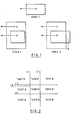
- Figure 1 shows various bounded areas, each of which consists of one or closed figures.
- points A are an odd number of boundary crossings from inifinity, and hence are inside the area.
- Points B are an even number, and hence outside. Rectangles have been used here for convenience, but the definition holds for closed figures of any shape.
- the 2-dimensional picture space is divided into 9 regions as is shown in Figure 2, by the four lines L1, L2, L3, and L4.
- the small central square is the correlation window.
- the point indicated by the operator is at the centre of this square. Any object . which intersects this square will register a 'hit'.
- the method used for the detection of the first of these conditions is Newman and Sproull's four-bit algorithm (note that this definition will actually cause an infinitely thin area, which may not even be visible, to be selectable).
- the method used for the second condition will now be described.
- the top left corner of the window has been arbitrarily chosen for testing the second condition.
- this test imagine scanning along the horizontal left-to-right line from infinity to the top left corner point (line L5). Each time a boundary line is crossed, the state flips between being inside and outside the area. Thus when the corner of the correlation window is reached, if an odd number of lines have been crossed we are inside the area, and if an even number (including zero) have been crossed, we are outside it.
- This information is recorded very simply by keeping an indicator bit.
- This bit is initialised to zero at the start of an area description, and whenever a boundary line is detected which crosses line L5, it is flipped (by performing an exclusive-OR operation with a one bit).
- the indicator bit is non-zero, condition 2 is satisfied, and the area does not intersect the correlation window.
- FIGS. 3A and B together show the steps in the preferred method of implementing the invention.
- the data display system in which the method is implemented is required to include the following registers:
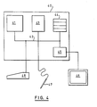
- FIG. 4 shows in block schematic form the apparatus in which the method described above can be implemented.
- a display control unit 40 contains a microprocessor 41 connected through a bus 42 to a read only store 43 which contains the control program for controlling the operations as set out with reference to Fig. 3.
- a random access store 44 has areas designated as registers x 1 y 1 : X 2 y 2 c 1 C 2 : X L X R , y T y B : and a code bit.
- a display buffer 45 holds the raster information for the display screen 46.
- a light pen 47 and a Keyboard 48 are connected through input ports to the bus 42.
- control program can be implemented as microcode in the read only memory implementation in a purpose built LS1 chip.
Landscapes
- Engineering & Computer Science (AREA)
- Theoretical Computer Science (AREA)
- Physics & Mathematics (AREA)
- General Physics & Mathematics (AREA)
- General Engineering & Computer Science (AREA)
- Human Computer Interaction (AREA)
- Software Systems (AREA)
- Computer Hardware Design (AREA)
- Geometry (AREA)
- Computer Graphics (AREA)
- Image Generation (AREA)
- Controls And Circuits For Display Device (AREA)
- Processing Or Creating Images (AREA)
- Digital Computer Display Output (AREA)
- Image Analysis (AREA)
Claims (3)
gekennzeichnet durch die folgenden weiteren Schritte:
Priority Applications (4)
| Application Number | Priority Date | Filing Date | Title |
|---|---|---|---|
| EP84301974A EP0156052B1 (de) | 1984-03-23 | 1984-03-23 | Interaktives Anzeigesystem |
| DE8484301974T DE3480811D1 (de) | 1984-03-23 | 1984-03-23 | Interaktives anzeigesystem. |
| JP59264694A JPS60202482A (ja) | 1984-03-23 | 1984-12-17 | 境界づけされた領域を識別する方法 |
| US07/082,978 US4814755A (en) | 1984-03-23 | 1987-08-04 | Interactive display system |
Applications Claiming Priority (1)
| Application Number | Priority Date | Filing Date | Title |
|---|---|---|---|
| EP84301974A EP0156052B1 (de) | 1984-03-23 | 1984-03-23 | Interaktives Anzeigesystem |
Publications (2)
| Publication Number | Publication Date |
|---|---|
| EP0156052A1 EP0156052A1 (de) | 1985-10-02 |
| EP0156052B1 true EP0156052B1 (de) | 1989-12-20 |
Family
ID=8192598
Family Applications (1)
| Application Number | Title | Priority Date | Filing Date |
|---|---|---|---|
| EP84301974A Expired EP0156052B1 (de) | 1984-03-23 | 1984-03-23 | Interaktives Anzeigesystem |
Country Status (4)
| Country | Link |
|---|---|
| US (1) | US4814755A (de) |
| EP (1) | EP0156052B1 (de) |
| JP (1) | JPS60202482A (de) |
| DE (1) | DE3480811D1 (de) |
Families Citing this family (15)
| Publication number | Priority date | Publication date | Assignee | Title |
|---|---|---|---|---|
| JPH0760375B2 (ja) * | 1986-12-04 | 1995-06-28 | 富士通株式会社 | マルチウィンドウ表示装置 |
| JPS63245576A (ja) * | 1987-03-31 | 1988-10-12 | Toshiba Corp | 面図形クリツプ回路 |
| US5021976A (en) * | 1988-11-14 | 1991-06-04 | Microelectronics And Computer Technology Corporation | Method and system for generating dynamic, interactive visual representations of information structures within a computer |
| WO1991004640A1 (en) * | 1989-09-11 | 1991-04-04 | Motorola, Inc. | Selective call receiver |
| US5208909A (en) * | 1989-10-23 | 1993-05-04 | International Business Machines Corporation | Pre-drawing pick detection in a graphics display system |
| US5414524A (en) * | 1992-01-14 | 1995-05-09 | Digital Equipment Corporation | Image rendering clip registers |
| US5757358A (en) * | 1992-03-31 | 1998-05-26 | The United States Of America As Represented By The Secretary Of The Navy | Method and apparatus for enhancing computer-user selection of computer-displayed objects through dynamic selection area and constant visual feedback |
| US5363483A (en) * | 1992-10-28 | 1994-11-08 | Intellution, Inc. | Updating objects displayed in a computer system |
| US5563990A (en) * | 1992-10-30 | 1996-10-08 | International Business Machines Corporation | Method and apparatus for processing a pick event |
| JP3794502B2 (ja) * | 1994-11-29 | 2006-07-05 | ソニー株式会社 | 画像領域抽出方法及び画像領域抽出装置 |
| JPH09128529A (ja) * | 1995-10-30 | 1997-05-16 | Sony Corp | ディジタル画像の雑音の投影に基づく除去方法 |
| JP3994445B2 (ja) * | 1995-12-05 | 2007-10-17 | ソニー株式会社 | 動きベクトル検出装置及び動きベクトル検出方法 |
| TW357327B (en) * | 1996-08-02 | 1999-05-01 | Sony Corp | Methods, apparatus and program storage device for removing scratch or wire noise, and recording media therefor |
| US6078616A (en) | 1997-03-13 | 2000-06-20 | Sony Corporation | Methods and apparatus for error concealment utilizing temporal domain motion vector estimation |
| US9569912B2 (en) | 2008-06-26 | 2017-02-14 | Shopatm Bv (Sarl) | Article storage and retrieval apparatus and vending machine |
Family Cites Families (5)
| Publication number | Priority date | Publication date | Assignee | Title |
|---|---|---|---|---|
| US31200A (en) * | 1861-01-22 | I H S White | Newspaper-file | |
| USRE31200F1 (en) | 1976-01-19 | 1990-05-29 | Raster scan display apparatus for dynamically viewing image elements stored in a random access memory array | |
| US4492956A (en) * | 1980-02-29 | 1985-01-08 | Calma Company | Graphics display system and method including preclipping circuit |
| US4412296A (en) * | 1981-06-10 | 1983-10-25 | Smiths Industries, Inc. | Graphics clipping circuit |
| US4587520A (en) * | 1983-04-07 | 1986-05-06 | Rca Corporation | Cursor controlled page selection in a video display |
-
1984
- 1984-03-23 EP EP84301974A patent/EP0156052B1/de not_active Expired
- 1984-03-23 DE DE8484301974T patent/DE3480811D1/de not_active Expired - Lifetime
- 1984-12-17 JP JP59264694A patent/JPS60202482A/ja active Pending
-
1987
- 1987-08-04 US US07/082,978 patent/US4814755A/en not_active Expired - Fee Related
Also Published As
| Publication number | Publication date |
|---|---|
| EP0156052A1 (de) | 1985-10-02 |
| JPS60202482A (ja) | 1985-10-12 |
| US4814755A (en) | 1989-03-21 |
| DE3480811D1 (de) | 1990-01-25 |
Similar Documents
| Publication | Publication Date | Title |
|---|---|---|
| US4814755A (en) | Interactive display system | |
| US6356281B1 (en) | Method and apparatus for displaying translucent overlapping graphical objects on a computer monitor | |
| JPH0560144B2 (de) | ||
| EP0702322B1 (de) | Verfahren und Gerät zur Identifikation von Wörtern, die in einem portablen elektronischen Dokument beschrieben sind | |
| EP0323558B1 (de) | Verfahren zum Füllen von Polygonen | |
| EP0780797A2 (de) | Verfahren und Vorrichtung zur Bestimmung von Gegenständen | |
| EP0425179A2 (de) | Objektauswahlerkennung in einem grafischen Anzeigesystem | |
| JPH0325574A (ja) | イメージ・エディタを作動する方法 | |
| EP0316144B1 (de) | Verfahren und Apparat zur Klassifizierung graphischer Segmente, um Auswahl- und Anzeigeoperation zu erleichtern | |
| EP0810514B1 (de) | Verfahren und System zur Erkennung von Zeigern | |
| US5020002A (en) | Method and apparatus for decomposing a quadrilateral figure for display and manipulation by a computer system | |
| US5442736A (en) | Correlation of cursor position to shapes displayed on a video display screen | |
| KR940006918B1 (ko) | 디지탈 활자체의 문자윤곽을 채우는 방법 및 시스템 | |
| US5491494A (en) | Pick correlation | |
| US5117485A (en) | Method and apparatus for sorting line segments for display and manipulation by a computer system | |
| US5563990A (en) | Method and apparatus for processing a pick event | |
| US5859643A (en) | Lowering geometric drawing resolution by filtering out data based on threshold values to increase retrieval speed | |
| US6304270B1 (en) | Method and apparatus for determining simple convex polygons | |
| US5644691A (en) | Method and apparatus for accelerated filling of polygons on a computer display by rectangular decomposition | |
| EP0163872A2 (de) | Verfahren zur Korrelation von Geraden in einem interaktiven Anzeigesystem | |
| EP0425171B1 (de) | Gegenstandidentifizierung in einem Anzeigesystem | |
| JPH02291083A (ja) | ピック処理方法 | |
| JPS62216085A (ja) | 折線グラフのハツチング処理方式 | |
| JPH06119443A (ja) | 線図形整形装置 | |
| JPS60263993A (ja) | デイスプレイ装置 |
Legal Events
| Date | Code | Title | Description |
|---|---|---|---|
| PUAI | Public reference made under article 153(3) epc to a published international application that has entered the european phase |
Free format text: ORIGINAL CODE: 0009012 |
|
| AK | Designated contracting states |
Designated state(s): DE FR GB IT |
|
| 17P | Request for examination filed |
Effective date: 19860124 |
|
| 17Q | First examination report despatched |
Effective date: 19870827 |
|
| GRAA | (expected) grant |
Free format text: ORIGINAL CODE: 0009210 |
|
| AK | Designated contracting states |
Kind code of ref document: B1 Designated state(s): DE FR GB IT |
|
| REF | Corresponds to: |
Ref document number: 3480811 Country of ref document: DE Date of ref document: 19900125 |
|
| ITF | It: translation for a ep patent filed | ||
| ET | Fr: translation filed | ||
| PLBE | No opposition filed within time limit |
Free format text: ORIGINAL CODE: 0009261 |
|
| STAA | Information on the status of an ep patent application or granted ep patent |
Free format text: STATUS: NO OPPOSITION FILED WITHIN TIME LIMIT |
|
| 26N | No opposition filed | ||
| ITTA | It: last paid annual fee | ||
| PGFP | Annual fee paid to national office [announced via postgrant information from national office to epo] |
Ref country code: GB Payment date: 19920210 Year of fee payment: 9 |
|
| PGFP | Annual fee paid to national office [announced via postgrant information from national office to epo] |
Ref country code: FR Payment date: 19920227 Year of fee payment: 9 |
|
| PGFP | Annual fee paid to national office [announced via postgrant information from national office to epo] |
Ref country code: DE Payment date: 19920321 Year of fee payment: 9 |
|
| PG25 | Lapsed in a contracting state [announced via postgrant information from national office to epo] |
Ref country code: GB Effective date: 19930323 |
|
| GBPC | Gb: european patent ceased through non-payment of renewal fee |
Effective date: 19930323 |
|
| PG25 | Lapsed in a contracting state [announced via postgrant information from national office to epo] |
Ref country code: FR Effective date: 19931130 |
|
| PG25 | Lapsed in a contracting state [announced via postgrant information from national office to epo] |
Ref country code: DE Effective date: 19931201 |
|
| REG | Reference to a national code |
Ref country code: FR Ref legal event code: ST |