EP0156238A2 - Mit Schaum gefüllte Einlage für das Eindringen in einen Horizontalkryostat - Google Patents
Mit Schaum gefüllte Einlage für das Eindringen in einen Horizontalkryostat Download PDFInfo
- Publication number
- EP0156238A2 EP0156238A2 EP85102817A EP85102817A EP0156238A2 EP 0156238 A2 EP0156238 A2 EP 0156238A2 EP 85102817 A EP85102817 A EP 85102817A EP 85102817 A EP85102817 A EP 85102817A EP 0156238 A2 EP0156238 A2 EP 0156238A2
- Authority
- EP
- European Patent Office
- Prior art keywords
- insert
- assembly
- tube
- disposed
- penetration
- Prior art date
- Legal status (The legal status is an assumption and is not a legal conclusion. Google has not performed a legal analysis and makes no representation as to the accuracy of the status listed.)
- Withdrawn
Links
Images
Classifications
-
- F—MECHANICAL ENGINEERING; LIGHTING; HEATING; WEAPONS; BLASTING
- F17—STORING OR DISTRIBUTING GASES OR LIQUIDS
- F17C—VESSELS FOR CONTAINING OR STORING COMPRESSED, LIQUEFIED OR SOLIDIFIED GASES; FIXED-CAPACITY GAS-HOLDERS; FILLING VESSELS WITH, OR DISCHARGING FROM VESSELS, COMPRESSED, LIQUEFIED, OR SOLIDIFIED GASES
- F17C3/00—Vessels not under pressure
- F17C3/02—Vessels not under pressure with provision for thermal insulation
- F17C3/08—Vessels not under pressure with provision for thermal insulation by vacuum spaces, e.g. Dewar flask
- F17C3/085—Cryostats
-
- F—MECHANICAL ENGINEERING; LIGHTING; HEATING; WEAPONS; BLASTING
- F17—STORING OR DISTRIBUTING GASES OR LIQUIDS
- F17C—VESSELS FOR CONTAINING OR STORING COMPRESSED, LIQUEFIED OR SOLIDIFIED GASES; FIXED-CAPACITY GAS-HOLDERS; FILLING VESSELS WITH, OR DISCHARGING FROM VESSELS, COMPRESSED, LIQUEFIED, OR SOLIDIFIED GASES
- F17C2203/00—Vessel construction, in particular walls or details thereof
- F17C2203/06—Materials for walls or layers thereof; Properties or structures of walls or their materials
- F17C2203/068—Special properties of materials for vessel walls
- F17C2203/0687—Special properties of materials for vessel walls superconducting
-
- F—MECHANICAL ENGINEERING; LIGHTING; HEATING; WEAPONS; BLASTING
- F17—STORING OR DISTRIBUTING GASES OR LIQUIDS
- F17C—VESSELS FOR CONTAINING OR STORING COMPRESSED, LIQUEFIED OR SOLIDIFIED GASES; FIXED-CAPACITY GAS-HOLDERS; FILLING VESSELS WITH, OR DISCHARGING FROM VESSELS, COMPRESSED, LIQUEFIED, OR SOLIDIFIED GASES
- F17C2221/00—Handled fluid, in particular type of fluid
- F17C2221/01—Pure fluids
- F17C2221/016—Noble gases (Ar, Kr, Xe)
- F17C2221/017—Helium
-
- F—MECHANICAL ENGINEERING; LIGHTING; HEATING; WEAPONS; BLASTING
- F17—STORING OR DISTRIBUTING GASES OR LIQUIDS
- F17C—VESSELS FOR CONTAINING OR STORING COMPRESSED, LIQUEFIED OR SOLIDIFIED GASES; FIXED-CAPACITY GAS-HOLDERS; FILLING VESSELS WITH, OR DISCHARGING FROM VESSELS, COMPRESSED, LIQUEFIED, OR SOLIDIFIED GASES
- F17C2270/00—Applications
- F17C2270/05—Applications for industrial use
- F17C2270/0527—Superconductors
- F17C2270/0536—Magnetic resonance imaging
-
- Y—GENERAL TAGGING OF NEW TECHNOLOGICAL DEVELOPMENTS; GENERAL TAGGING OF CROSS-SECTIONAL TECHNOLOGIES SPANNING OVER SEVERAL SECTIONS OF THE IPC; TECHNICAL SUBJECTS COVERED BY FORMER USPC CROSS-REFERENCE ART COLLECTIONS [XRACs] AND DIGESTS
- Y10—TECHNICAL SUBJECTS COVERED BY FORMER USPC
- Y10S—TECHNICAL SUBJECTS COVERED BY FORMER USPC CROSS-REFERENCE ART COLLECTIONS [XRACs] AND DIGESTS
- Y10S220/00—Receptacles
- Y10S220/901—Liquified gas content, cryogenic
Definitions
- the present invention is generally directed to horizontal penetrations extending between the inner and outer walls of a cryostat, particularly one employing liquid helium as a coolant material. More particularly, the present invention is directed to an insert for this penetration which employs a large plurality of foam spheres for insulation and blowout protection. Even more particularly, the present invention is directed to a cryostat insert for horizontal penetrations in which electrically conductive leads extend from the penetration in normal operation (that is, non-retractable leads).
- cryostat In the generation of medical diagnostic images in nuclear magnetic resonance imaging, it is necessary to provide a temporally stable and spatially homogenous magnetic field.
- the use of superconductive electrical materials maintained at a temperature below their critical transition temperatures provides an advantageous means to produce such a field. Accordingly, for such NMR imaging devices, a cryostat is employed.
- the cryostat contains an innermost chamber in which liquid helium, for example, is employed to cool the superconductive materials.
- the cryostat itself typically comprises a toroidal structure with other nested toroidal structures inside the exterior vessel to provide vacuum conditions, intermediate liquid nitrogen cooling and thermal shielding.
- This layering provides a natural form of thermal insulation along the length of a vertical penetration.
- the temperature profile is substantially constant.
- any layering that would result would not be in a direction of the long axis of the cryostat penetration.
- the temperature gradient along the penetration would tend to set up free convection currents in the vapor within the penetration. This would result in a much more rapid loss of coolant than is desired. Since the cost of helium is relatively high, it is seen that the loss of coolant is undesirable.
- cryostat penetrations should usually be provided with pressure relief means.
- vacuum conditions are maintained between the innermost and outermost cryostat vessels. If for some reason, a loss of vacuum occurs in this volume, it is also possible to develop a rapid increase in the coolant vapor pressure. For this reason also, pressure relief means are desirable for cryostat penetrations.
- cryostat wall As indicated above, electrical connection must be provided through the cryostat wall to accommodate the electrical apparatus contained therein at the desired lower temperature.
- the electrical connections to the internal coils are made through an electrical lead assembly which is disposed entirely within an inner cryostat vessel.
- frost buildup upon the contacts and these contacts often must be heated to a temperature of about 300 0 K prior to making an electrical connection to them. It is, of course, undesirable that interior cryostat objects must be heated.
- a persistent current mode of operation is intended.
- an insert for a horizontal cryostat penetration comprises an outer, low thermal conductivity tube (or conduit) together with an inner, low thermal conductivity tube (or conduit) disposed substantially coaxially with respect to the outer tube.
- a plurality of foam pieces or spheres is disposed between the inner and outer tubes which are sealably affixed to an annular chamber so as to define an enclosed volume.
- the annular chamber is provided with blowout means, preferably in the form of a rupture disk. In the event of vacuum loss or magnet quench resulting in coolant vapor pressure buildup, the foam spheres are safely ejected through the broken rupture disk.
- the annular chamber also preferably includes a means for sealing the space around an electrical conductor extending through the central aperture in the annulus. Thermally conductive baffles are also provided to partition the foam spheres into a plurality of annular volumes.
- the insert described briefly above is employed in a horizontal cryostat penetration assembly which further includes a thin wall stationary tubular conduit disposed sealably between inner and outer cryostat vessel walls.
- the outer surface of the outer tube in the above-described insert preferably includes helically machined grooves therein for the purpose of holding an elongate strip of sealing material such as twine. This configuration produces a helical coolant vapor flowpath between the stationary and removable portions of the cryostat penetration.
- the insert and insert assembly of the present invention are particularly useful in liquid helium cryostats employing non-retractable electrical leads.
- the insert and assembly of the present invention are particularly applicable for temporary utilization during magnet excitation.
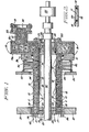
- Figure 1 illustrates a horizontal cryostat penetration in which,there are shown two distinct and separable assemblies.
- the particular elements which comprise these two assemblies are described in detail below. Suffice it to say for now that the two assemblies essentially comprise the stationary parts of the cryostat itself and the removable insert assembly in accordance with one embodiment of the present invention.
- the cryostat includes inner vessel wall 37 and outermost vessel wall 33 with aperture 34 therein through which the penetration assembly of the present invention is disposed. In operation, vacuum conditions are maintained between these walls.
- Figure 1 illustrates the presence of a limited number of vessel walls, it should be understood that other intermediate vessel walls may be provided as circumstances dictate in various cryostat designs.
- bellows assembly 32 is typically disposed between outermost vessel wall 33 and flange 31. Wall 37 and flange 31 are both provided with aligned apertures for accommodation of the horizontal penetration. More particularly, collar 36 is typically disposed in an aperture in wall 37 and is sealed to wall 37 for example, by welding.
- Inner vessel wall 37 and collar 36 typically comprises materials such as aluminum.
- Outmost vessel wall 33 and flange 31 typically comprise a low thermal conductivity material such as stainless steel.
- the stationary cryostat structure also includes fixed tubular conduit 30 which passes at least partially through apertures in walls 37 and 33. Additionally stationary conduit 30 is sealably joined to walls 37 and flange 31. In particular, in the case of wall 37, tubular conduit 30 is adjoined thereto by means of collar 36.
- Stationary tubular conduit 30 typically comprises a low thermal conductivity material such as stainless steel.
- the stationary cryostat structure includes non-retractable electrical lead 35. Accordingly, it is seen that walls 33 and 37, flange 31, collar 36, electrical lead 35 and conduit 30 comprise a stationary structure for which the insert assembly of the present invention may be employed.
- the remaining structures of Figure 1 comprise the insert or insert assembly of the present invention.
- the insert assembly of the present invention includes outer tube 12, inner tube 16, annular chamber 19, foam particles or spheres 15, rupture disk 20 and other structures which are more particularly described below.
- annular chamber 19 permits the disposition therethrough of electrical conduit 35.
- conduit 35 is described herein as a single electrical lead, it is nonetheless understood that this lead provides electrical connection for a number of internal electrical components including the magnet coils, correction coils and gradient coils, as needed or desired in various applications, including NMR diagnostic imaging.
- the use of an annular exterior chamber 19 in the manner illustrated in Figure 1 is also at least partially motivated by the general undesirability of employing annular blowout or rupture disks.
- Figure 1 illustrates outer thin wall tube 12 which is sealably attached to washer-shaped wall 19a of annular chamber 19.
- Inner thin wall tube 16 is also sealably affixed to a wall of chamber 19, namely washer-shaped wall 19c.
- Tube 16 is preferably aligned so as to be coaxial with tube 12 so as to define an annular volume therebetween.
- This volume is preferably filled with foam pieces or spheres 15 typically having a diameter of approximately 1/16 to 1/8 inch. These spheres provide an insulating function and yet at the same time may be safely ejected from any holes occurring in burst disk 20.
- These spheres also preferably fill the interior volume of annular chamber 19.
- a plurality of high thermal conductivity disks 14 are disposed within the volume between tubes 12 and 16 . These disks preferably comprise copper or aluminum foil in contact with tubes 12 and 16. These annular baffles help to prevent free convection currents of helium vapor from establishing themselves in the horizontal penetration. These baffles provide isothermal surfaces, limit vapor flow and generally reduce temperature gradients in a transverse direction in the penetration.
- --Baffles 14 may be designed so as to be sufficiently thin so as to be ejected with spheres 15 or may be provided with sufficient rigidity that over pressure conditions result in these baffles being forced against wall 19c of chamber 19.
- Tubes 12 and 16 preferably comprise low thermal conductivity material and for similar reasons, also comprise thin walled sections.
- Annular chamber 19 includes annular member 19a to which tube 12 is sealably joined, as for example, by welding.
- Chamber 19 also includes annular member 19c to which tube 16 is attached, again for example, as by welding.
- Cylindrical member 19b also comprises chamber 19 and it is wall member 19b to which annular members 19a and 19c are sealably attached, again preferably by welding.
- Annular disk-shaped member 19c is therefore seen to be possessed of an aperture having a smaller diameter than the aperture in wall 19a. Accordingly, annular chamber 19 is seen to possess an inner aperture through which electrical conduit 35 may be disposed.
- chamber 19, and in particular wall 19a includes an annular groove in which O-ring 25 is disposed so that chamber 19 may be sealably affixed to vessel flange 31.
- annular screen 17 is attached to tubes 12 and 16 as a means for containing spheres 15, to the extent that such retention is not in fact accomplished by means of baffles 14. Screen 17 is therefore seen to preferably comprise a member which is readily penetrable by a gaseous flow.
- Collar 21 with flange 22 is sealably affixed in an aperture in wall member 19c of annular chamber 19.
- Annular retention clamp 18 is affixed to flange 22 so as to hold rupture disk 20 in position so as to provide an airtight seal.
- the inner volume of chamber 19 is also preferably filled with foam spheres 15, as shown. In the event that rupture disk 20 is broken as a result of overpressure conditions, spheres 15 are safely but rapidly ejected from the insert assembly.
- the spheres themselves may for example, comprise material such as styrofoam and are preferably about 1/16 to 1/8 inch in diameter.
- split ring support collar 26 together with a matching split ring collar half, is disposed about conductor 35, as shown.
- Split ring collar 26 is also seen as being disposed with in the central aperture of annular chamber 19.
- flanged collar 23 bolted to wall member 19c of chamber 19 is also provided so that split ring collar 26 may extend at least partially therethrough.
- a spirally configured length of sealing material such as a strip of leather 24, is disposed in contact with split ring collar 26, flanged collar 23 and inner tube 16 as shown.
- conductor 35 is seen to be supported with a sealing .
- plug assembly comprising split rings 27 and 28 between which is disposed gasket 29, preferably comprising leather.
- Figure 1 Another important feature of the present invention that is illustrated in Figure 1 is that there is disposed about the exterior of outer tube 12, a string-like length of sealing material 13 arranged in a substantially helical pattern between outer tube 12 and stationary tube 30. Sealing material 13 may comprise gasket material or may simply comprise a length of twine. It is additionally noted that Figure 1 depicts sealing material 13 as being disposed in a helical pattern exhibiting a variable pitch. In particular, sealing material 13 is disposed so that the pitch of the helical pattern increases in a direction extending from inner vessel wall 37 to outer vessel flange 31.
- sealing material 13 provides a helical flowpath for coolant vapor from the interior to the exterior of the cryostat.
- Figure 1 illustrates coolant flow arrow 41 directed to the start of the helical path which extends around and along gap 11 between tubes 12 and 30.
- the coolant vapor exits the exterior end of gap 11 and is ultimately exhausted to the exterior ambient environment through channel 38 in wall 31, as indicated by flow arrow 39. It is also, in particular, noted that this flowpath is not in fluid communication with the interior annular volume between tubes 12 and 16, that is the volume occupied by spheres 15 (except at the cold, interior end of the of the penetration insert). Accordingly, the axial and circumferential flow occurring in gap 11 is not shared by the vapor surrounding spheres 15. It is also seen that chamber 19 together with tubes 12 and 16 and the helically disposed sealing material 13 are readily removable from the cryostat.
- Figure 1 Since several of the structures shown in Figure 1 are in fact thin-walled structures, clarity of illustration is enhanced in Figure 1 by the depiction of these elements as single lines. In particular, this is true of stationary tube 30, outer tube 12 and inner tube 16. Accordingly, Figure 2 provides an enlarged cross-sectional view of a portion of the thin-walled structure employed herein. All the elements illustrated in Figure 2 have been described above. However, it is notable to observe that sealing material 13 may in fact be disposed in helical grooves provided in outer tube 12. Such a construction facilitates removal of the insert assembly of the present invention. However, those skilled in the art will readily appreciate that it is also possible to provide stationary tube 30 with similar helically disposed grooves. However, such is not the preferred embodiment of the present invention.
- tube or tubular is not restricted to objects exhibiting circular cross-sections, but also includes cylindrical (in its general sense) structures having oval, elliptical, square and similar cross-sections. Accordingly, chamber 19 is also described above as being annular. However, it is well understood that departure from this shape too is readily provided in the same fashion without departing from the principles of the of present invention.
- this tube 12 preferably comprises a glass fiber composite material.
- gap 11 between conduits 30 and 12 is typically between about 2 mils and about 10 mils.
- Thermally conductive baffles 14 are typically between about 1 and about 5 mils in thickness and comprise high thermal conductivity material such as copper or aluminum foil.
- the penetration insert assembly of the present invention provides a thermally efficient horizontal cryostat penetration which is particularly useful for non-retractable electrical leads.
- the present invention significantly mitigates any effects resulting from free convection secondary flows in the penetration itself.
- the present invention provides a high degree of thermal insulation in a manner which does not impede the exhaust of coolant gasses in the event of magnet quench or vacuum loss.
- the present invention provides a thermally efficient horizontal cryostat penetration insert assembly that reliably relieves internal vapor pressure.
Landscapes
- Engineering & Computer Science (AREA)
- Physics & Mathematics (AREA)
- Thermal Sciences (AREA)
- Mechanical Engineering (AREA)
- General Engineering & Computer Science (AREA)
- Containers, Films, And Cooling For Superconductive Devices (AREA)
- Magnetic Resonance Imaging Apparatus (AREA)
- Thermal Insulation (AREA)
Applications Claiming Priority (2)
| Application Number | Priority Date | Filing Date | Title |
|---|---|---|---|
| US06/595,201 US4516404A (en) | 1984-03-30 | 1984-03-30 | Foam filled insert for horizontal cryostat penetrations |
| US595201 | 1984-03-30 |
Publications (2)
| Publication Number | Publication Date |
|---|---|
| EP0156238A2 true EP0156238A2 (de) | 1985-10-02 |
| EP0156238A3 EP0156238A3 (en) | 1986-10-08 |
Family
ID=24382197
Family Applications (1)
| Application Number | Title | Priority Date | Filing Date |
|---|---|---|---|
| EP19850102817 Withdrawn EP0156238A3 (en) | 1984-03-30 | 1985-03-12 | Foam filled insert for horizontal cryostat penetrations |
Country Status (5)
| Country | Link |
|---|---|
| US (1) | US4516404A (de) |
| EP (1) | EP0156238A3 (de) |
| JP (1) | JPS60259939A (de) |
| CA (1) | CA1241591A (de) |
| IL (1) | IL74638A0 (de) |
Cited By (2)
| Publication number | Priority date | Publication date | Assignee | Title |
|---|---|---|---|---|
| WO1988009055A1 (en) * | 1987-05-07 | 1988-11-17 | Ncr Corporation | Carbon connectors to liquid-immersion cooled integrated circuit |
| EP0350266A3 (de) * | 1988-07-05 | 1991-01-23 | General Electric Company | Verbindung eines kryogenen Kühlers mit einem zu kühlenden Körper |
Families Citing this family (21)
| Publication number | Priority date | Publication date | Assignee | Title |
|---|---|---|---|---|
| EP0375656B1 (de) * | 1985-01-17 | 1993-11-24 | Mitsubishi Denki Kabushiki Kaisha | Kryogenisches Gefäss für einen supraleitenden Apparat |
| IL75968A (en) * | 1985-07-30 | 1989-09-28 | Elscint Ltd | Turret for cryostat |
| US4633682A (en) * | 1986-02-04 | 1987-01-06 | General Electric Company | Horizontal cryostat insert with a vertical service stack |
| US4635451A (en) * | 1986-02-04 | 1987-01-13 | General Electric Company | Spring loaded valve for adding cryogenic liquid to a cryostat |
| US4635450A (en) * | 1986-02-04 | 1987-01-13 | General Electric Company | Compact retractable cryogenic leads |
| US4667486A (en) * | 1986-05-05 | 1987-05-26 | General Electric Company | Refrigerated penetration insert for cryostat with axial thermal disconnect |
| US4667487A (en) * | 1986-05-05 | 1987-05-26 | General Electric Company | Refrigerated penetration insert for cryostat with rotating thermal disconnect |
| US4872322A (en) * | 1988-09-02 | 1989-10-10 | General Electric Company | Power operated contact apparatus for superconductive circuit |
| DE3915788C2 (de) * | 1989-05-13 | 1994-09-15 | Spectrospin Ag | Kryostat mit einem Überdruckdeckel |
| US5009073A (en) * | 1990-05-01 | 1991-04-23 | Marin Tek, Inc. | Fast cycle cryogenic flex probe |
| US5247800A (en) * | 1992-06-03 | 1993-09-28 | General Electric Company | Thermal connector with an embossed contact for a cryogenic apparatus |
| JP2758786B2 (ja) * | 1992-07-30 | 1998-05-28 | 三菱電機株式会社 | 超電導マグネット |
| GB2307045B (en) * | 1995-11-08 | 2000-06-14 | Oxford Magnet Tech | Improvements in or relating to super-conducting nagnets |
| US6109042A (en) * | 1998-12-12 | 2000-08-29 | General Electric Company | Superconducting magnet burst disk venting mechanism |
| US7489131B2 (en) * | 2007-04-23 | 2009-02-10 | General Electric Co. | System and apparatus for direct cooling of gradient coils |
| JP5426266B2 (ja) * | 2009-05-25 | 2014-02-26 | ジャパンマリンユナイテッド株式会社 | 液化ガスタンクのドーム構造 |
| US20160322143A1 (en) * | 2013-12-18 | 2016-11-03 | Victoria Link Limited | Cryostat for Superconducting Devices |
| US10761162B2 (en) | 2018-09-18 | 2020-09-01 | General Electric Company | Gradient coil cooling systems |
| US11313481B2 (en) * | 2019-08-28 | 2022-04-26 | GE Precision Healthcare LLC | Systems for rupturing a vacuum in a medical imaging device |
| US12523343B2 (en) * | 2020-11-10 | 2026-01-13 | Cryoshelter LH2 GmbH | System comprising a cryogenic container and a thermal siphon |
| EP4609106A1 (de) * | 2022-10-26 | 2025-09-03 | Linde GmbH | Speicherbehälter |
Family Cites Families (7)
| Publication number | Priority date | Publication date | Assignee | Title |
|---|---|---|---|---|
| US3066222A (en) * | 1959-11-18 | 1962-11-27 | Union Carbide Corp | Infra-red detection apparatus |
| US3309884A (en) * | 1965-10-11 | 1967-03-21 | Richard S Pauliukonis | Dewar design for storage and transportation of low temperature fluids |
| US3377813A (en) * | 1965-10-22 | 1968-04-16 | Cryogenic Eng Co | Storage container |
| US3483709A (en) * | 1967-07-21 | 1969-12-16 | Princeton Gamma Tech Inc | Low temperature system |
| US3714942A (en) * | 1969-02-03 | 1973-02-06 | Sub Marine Syst Inc | Cryogenic gas processing system |
| US4223540A (en) * | 1979-03-02 | 1980-09-23 | Air Products And Chemicals, Inc. | Dewar and removable refrigerator for maintaining liquefied gas inventory |
| US4492090A (en) * | 1983-09-19 | 1985-01-08 | General Electric Company | Cryostat for NMR magnet |
-
1984
- 1984-03-30 US US06/595,201 patent/US4516404A/en not_active Expired - Fee Related
-
1985
- 1985-03-12 EP EP19850102817 patent/EP0156238A3/en not_active Withdrawn
- 1985-03-18 IL IL74638A patent/IL74638A0/xx unknown
- 1985-03-28 CA CA000477821A patent/CA1241591A/en not_active Expired
- 1985-03-29 JP JP60064018A patent/JPS60259939A/ja active Pending
Cited By (3)
| Publication number | Priority date | Publication date | Assignee | Title |
|---|---|---|---|---|
| WO1988009055A1 (en) * | 1987-05-07 | 1988-11-17 | Ncr Corporation | Carbon connectors to liquid-immersion cooled integrated circuit |
| US4800422A (en) * | 1987-05-07 | 1989-01-24 | Ncr Corporation | Frostless interface supercooled VLSI system |
| EP0350266A3 (de) * | 1988-07-05 | 1991-01-23 | General Electric Company | Verbindung eines kryogenen Kühlers mit einem zu kühlenden Körper |
Also Published As
| Publication number | Publication date |
|---|---|
| JPS60259939A (ja) | 1985-12-23 |
| EP0156238A3 (en) | 1986-10-08 |
| US4516404A (en) | 1985-05-14 |
| IL74638A0 (en) | 1985-06-30 |
| CA1241591A (en) | 1988-09-06 |
Similar Documents
| Publication | Publication Date | Title |
|---|---|---|
| US4516404A (en) | Foam filled insert for horizontal cryostat penetrations | |
| US4535596A (en) | Plug for horizontal cryostat penetration | |
| US4522034A (en) | Horizontal cryostat penetration insert and assembly | |
| US8279030B2 (en) | Method and apparatus for electrical, mechanical and thermal isolation of superconductive magnets | |
| EP0350267B1 (de) | Supraleitender Magnetresonanz-Magnet | |
| EP0350262B1 (de) | Stützvorrichtung einer Strahlungsabschirmung in einem Magnetresonanz-Magneten | |
| US4895831A (en) | Ceramic superconductor cryogenic current lead | |
| EP0482840B1 (de) | Hybrider dampfgekühlter Energieanschluss für einen Kryostat | |
| US4902995A (en) | Cable suspension system for cylindrical cryogenic vessels | |
| EP0392771B1 (de) | Cryogenischer Vorkühler für einen supraleitenden Magneten | |
| EP1744170A1 (de) | Kaltmassestruktur mit geringem Feldverlust für supraleitende Magneten | |
| US5381122A (en) | Open MRI magnet having a support structure | |
| EP0781956B1 (de) | Konvektionskühlung von Balgkonvolutionen unter Verwendung von einem Durchdringungsrohr mit Muffe | |
| EP1115997A2 (de) | Supraleitende vorrichtungen und kühlverfahren | |
| US4562703A (en) | Plug tube for NMR magnet cryostat | |
| US4394634A (en) | Vapor cooled current lead for cryogenic electrical equipment | |
| US6323749B1 (en) | MRI with superconducting coil | |
| US4633682A (en) | Horizontal cryostat insert with a vertical service stack | |
| EP0395877B1 (de) | Kryovorkühler für supraleitende Magnete | |
| US4635451A (en) | Spring loaded valve for adding cryogenic liquid to a cryostat | |
| JP2013507753A (ja) | 超伝導磁石の電気的、機械的、熱的隔離方法および装置 | |
| US12142421B2 (en) | Apparatus and system to enhance thermal gradients in cryogenic devices |
Legal Events
| Date | Code | Title | Description |
|---|---|---|---|
| PUAI | Public reference made under article 153(3) epc to a published international application that has entered the european phase |
Free format text: ORIGINAL CODE: 0009012 |
|
| AK | Designated contracting states |
Designated state(s): CH DE FR GB IT LI NL SE |
|
| PUAL | Search report despatched |
Free format text: ORIGINAL CODE: 0009013 |
|
| AK | Designated contracting states |
Kind code of ref document: A3 Designated state(s): CH DE FR GB IT LI NL SE |
|
| 17P | Request for examination filed |
Effective date: 19861105 |
|
| 17Q | First examination report despatched |
Effective date: 19880613 |
|
| STAA | Information on the status of an ep patent application or granted ep patent |
Free format text: STATUS: THE APPLICATION IS DEEMED TO BE WITHDRAWN |
|
| 18D | Application deemed to be withdrawn |
Effective date: 19881001 |
|
| RIN1 | Information on inventor provided before grant (corrected) |
Inventor name: LASKARIS, EVANGELOS TRIFON |