EP0156358A2 - Méthode et dispositif pour la commande électronique de l'injection de carburant d'un moteur à combustion interne - Google Patents
Méthode et dispositif pour la commande électronique de l'injection de carburant d'un moteur à combustion interne Download PDFInfo
- Publication number
- EP0156358A2 EP0156358A2 EP85103566A EP85103566A EP0156358A2 EP 0156358 A2 EP0156358 A2 EP 0156358A2 EP 85103566 A EP85103566 A EP 85103566A EP 85103566 A EP85103566 A EP 85103566A EP 0156358 A2 EP0156358 A2 EP 0156358A2
- Authority
- EP
- European Patent Office
- Prior art keywords
- deceleration
- throttle
- throttle aperture
- correction
- fuel injection
- Prior art date
- Legal status (The legal status is an assumption and is not a legal conclusion. Google has not performed a legal analysis and makes no representation as to the accuracy of the status listed.)
- Withdrawn
Links
Images



Classifications
-
- F—MECHANICAL ENGINEERING; LIGHTING; HEATING; WEAPONS; BLASTING
- F02—COMBUSTION ENGINES; HOT-GAS OR COMBUSTION-PRODUCT ENGINE PLANTS
- F02D—CONTROLLING COMBUSTION ENGINES
- F02D41/00—Electrical control of supply of combustible mixture or its constituents
-
- F—MECHANICAL ENGINEERING; LIGHTING; HEATING; WEAPONS; BLASTING
- F02—COMBUSTION ENGINES; HOT-GAS OR COMBUSTION-PRODUCT ENGINE PLANTS
- F02D—CONTROLLING COMBUSTION ENGINES
- F02D41/00—Electrical control of supply of combustible mixture or its constituents
- F02D41/02—Circuit arrangements for generating control signals
- F02D41/04—Introducing corrections for particular operating conditions
- F02D41/12—Introducing corrections for particular operating conditions for deceleration
Definitions
- the present invention generally relates to a method and an apparatus for electronically controlling fuel injection for an internal combustion engine. More particularly, the invention is directed to the provision of an electronically controlled fuel injection system which can assure an improved operation performance and optimum air-fuel ratio control by correcting deceleration for compensating delay involved in the air-fuel ratio control based on an air flow sensor in dependence on the opening degree of a throttle valve.
- the air flow fed to an internal combustion engine varies in proportional dependence on the opening degree of a throttle valve (also referred to as the throttle aperture).
- a throttle valve also referred to as the throttle aperture
- the air flow can not immediately follow up the change in the throttle aperture.
- the air flow can vary correspondingly only with a time lag. This can be explained by the fast that the air suction passage extending from the position of the throttle valve has a predetermined length and that the air flow sensor is disposed at a position upstream of the throttle valve. Under the circumstance, the air-fuel ratio control can not be accomplished in a satisfactory-manner.
- correction of decelation is effected by using a so-called throttle sensor. More specifically, when rate of change or derivate of the output signal exceeds a predetermined value, the amount of fuel supply arithmetically determined on the basis of the amount of intake air detected by the air flow sensor is corrected by multiplying with a coefficient of a certain value (e.g. 0.9). This correction is referred to as the correction of decelation while the coefficient being referred to as the deceleration correcting coefficient.
- the known decelation correcting system is however disadvantageous in that the correction is made to a same extent for different changes in the throttle aperture. For example, referring to Fig.
- An object of the present invention is to provide a method and an apparatus for electrically controlling fuel injection for an internal combustion engine which is capable of realizing the optimum air-fuel ratio control by correcting or compensating the delay involved in the control described above.
- the throttle aperture is periodically sampled at a predetermined time interval to determine the rate of change or derivative of the throttle aperture for detecting deceleration, wherein upon every detection of the deceleration, the correcting value is accumulated, to allow a large magnitude of the change in the throttle aperture to be discriminated from a small change thereof for realizing the optimum correction of deceleration and hence the optimum air-fuel ratio control.
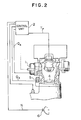
- Fig. 2 shows an internal combustion engine to which the present invention can be applied.
- the air sucked into an internal combustion engine is measured by an air flow sensor 1.
- the value of the air flow as detected by the sensor 1 is supplied to a control unit 2 which is so arranged as to arithmetically determine the amount of fuel to be supplied to the engine on the basis of engine revolution number N which is determined by counting pulses generated by a crank angle sensor 6, whereby a number of pulses corresponding to the determined amount of fuel are outputted to a fuel injector 3, resulting in that the amount of fuel corresponding to the input pulse number is ejected.
- the pulse width T of the basic pulse supplied to the injector 3 is given by the following expression where k represents a constant.
- an output signal of a throttle sensor 5 which is representative of the aperture (i.e. opening degree) of a throttle valve 4 is sampled and fetched periodically at a time interval T 1 (e.g. every 10 msec), as is illustrated in Fig. 3, to examine rate of change (or derivative) ⁇ in the throttle aperture.
- T 1 e.g. every 10 msec
- rate of change (or derivative) ⁇ in the throttle aperture e.g. every 10 msec
- a corresponding deceleration correcting coefficient k D2 is set in accordance with the decision to the effect that greater deceleration occurs than in the case of ⁇ 1 .
- ⁇ x-1 ⁇ x ⁇ 3 where ⁇ 3 represents a third rate of change in the throttle aperture, it is decided that corresponding deceleration is greater than in the case of ⁇ 2 , to thereby set a deceleration correcting coefficient k D3 .
- correspondences between ⁇ 1, ⁇ 2 and ⁇ 3 and k Dl' k D2 and k D3 may be, for example, set as follows:
- deceleration correcting coefficients k D are employed for correcting the width of the injection pulse in accordance with the following expression:
- a same correction is performed for both decelerations to the levels A and B (see Fig. 1), which means that a correcting coefficient suited for the deceleration or slow- down to the level A is inadequate for the deceleration to the level B, resulting in that quality of the discharged gas is degraded.
- the correcting coefficient determined for the deceleration to the level B involves correction in excess for the deceleration to the level A, giving rise to occurrence of discomfortable shocks.
- the deceleration correcting coefficient k D2 is selected to determine the value of correction with the preceding correction being added, as follows:
- the deceleration correction coefficient k Dl is selected to determine the value of correction with the preceding correction being added, as follows:
- the deceleration correcting coefficient k D approached or rises up to 1.0 linearly from a time point (T 1 - T 4 ) or (T 2 - T 4 ) during a period T 4 .
- Fig. 5 is a flow chart for illustrating the control procedure on the assumption that two deceleration correcting coefficients ( ⁇ 1 and ⁇ 2 ) are employed.
- the throttle aperture (i.e. opening degree of the throttle valve) T HV is set at the preceding throttle aperture TEVOLD which is then stored in a memory.
- the current throttle aperture T EV is sampled and stored in a memory area reserved for storing the current throttle aperture.
- the correcting coefficient k Di is determined at a step 109. Further, when it is decided at the step 104 that ⁇ TH ⁇ 0 (zero) and when it is decided at the step 105 that AT ⁇ ⁇ 1, then the correcting coefficient k D is set to 1 (one) at a step 108, while the sampling timer T M is set to zero (reset) with the deceleration time also being set to zero.
- the deceleration time T DEC is set to T 2 at a step 110.
- the deceleration time T DEC is set to T 1 .
- time T 3 is set at the timer T M at a step 112.
- the decision step 113 results in "NO"
- the deceleration time T DEC is set as it is at a step 115, which is followed by a step 116 where it is decided whether the set deceleration time T DEC is greater than or equal to a time T4 .
- the deceleration correcting coefficient K DECS set at the step 107 is set as the deceleration correcting coefficient K DEC at a step 117.
- decision at the step 116 results in that T DEC ⁇ T 4
- deceleration correcting coefficient K DEC is determined at a step 118, which is followed by a step 119 where decision is made as to whether the timer is 0 (zero).
- the decision step 119 results in that the timer is 0 (zero)
- the second limit value K min 2 is set as the deceleration correcting coefficient.
- the decision step 119 results in that the timer T M is not zero, the timer is set at a step 122, which is followed by the step 123 where decision is made as to whether the deceleration correcting coefficient K DEC is greater than the first limit value K min 1 , inclusive thereof.
- the step 125 is then executed. Otherwise, the first limit value is set as the deceleration correcting coefficient.
- the basic pulse width T p is multiplied with the deceleration correcting coefficient K DEC to produce the injection pulse width T i .
- the injection pulse width T i is loaded in an output register.
Landscapes
- Engineering & Computer Science (AREA)
- Chemical & Material Sciences (AREA)
- Combustion & Propulsion (AREA)
- Mechanical Engineering (AREA)
- General Engineering & Computer Science (AREA)
- Electrical Control Of Air Or Fuel Supplied To Internal-Combustion Engine (AREA)
Applications Claiming Priority (2)
| Application Number | Priority Date | Filing Date | Title |
|---|---|---|---|
| JP59059133A JPS60201049A (ja) | 1984-03-27 | 1984-03-27 | 電子制御燃料噴射装置 |
| JP59133/84 | 1984-03-27 |
Publications (2)
| Publication Number | Publication Date |
|---|---|
| EP0156358A2 true EP0156358A2 (fr) | 1985-10-02 |
| EP0156358A3 EP0156358A3 (fr) | 1986-03-19 |
Family
ID=13104508
Family Applications (1)
| Application Number | Title | Priority Date | Filing Date |
|---|---|---|---|
| EP85103566A Withdrawn EP0156358A3 (fr) | 1984-03-27 | 1985-03-26 | Méthode et dispositif pour la commande électronique de l'injection de carburant d'un moteur à combustion interne |
Country Status (5)
| Country | Link |
|---|---|
| US (1) | US4644923A (fr) |
| EP (1) | EP0156358A3 (fr) |
| JP (1) | JPS60201049A (fr) |
| KR (1) | KR850007635A (fr) |
| CA (1) | CA1241092A (fr) |
Families Citing this family (6)
| Publication number | Priority date | Publication date | Assignee | Title |
|---|---|---|---|---|
| JPS62206250A (ja) * | 1986-03-05 | 1987-09-10 | Mazda Motor Corp | エンジンの燃料制御装置 |
| JPS62279245A (ja) * | 1986-05-29 | 1987-12-04 | Nissan Motor Co Ltd | 空燃比制御装置 |
| DE3628628C2 (de) * | 1986-08-22 | 1994-12-08 | Bosch Gmbh Robert | Verfahren und Einrichtung zur Adaption der Gemischsteuerung bei Brennkraftmaschinen |
| JPH03225049A (ja) * | 1990-01-31 | 1991-10-04 | Toyota Motor Corp | 内燃機関の空燃比制御装置 |
| JP2507908Y2 (ja) * | 1990-02-03 | 1996-08-21 | 株式会社タチエス | 可倒式シ―トバックのロック装置 |
| KR101644756B1 (ko) | 2015-10-01 | 2016-08-01 | 박용환 | 튜브용 필러가 구비된 휴대용 팽창식 구명정 |
Family Cites Families (8)
| Publication number | Priority date | Publication date | Assignee | Title |
|---|---|---|---|---|
| JPS5791339A (en) * | 1980-11-26 | 1982-06-07 | Mitsubishi Motors Corp | Fuel supply equipment for engine |
| US4359993A (en) * | 1981-01-26 | 1982-11-23 | General Motors Corporation | Internal combustion engine transient fuel control apparatus |
| JPS57143136A (en) * | 1981-02-26 | 1982-09-04 | Toyota Motor Corp | Method of controlling air fuel ratio of internal combustion engine |
| JPS5828568A (ja) * | 1981-08-13 | 1983-02-19 | Toyota Motor Corp | 内燃機関の燃料供給量制御方法 |
| JPS5848725A (ja) * | 1981-09-18 | 1983-03-22 | Toyota Motor Corp | 燃料噴射制御方法 |
| JPS58144635A (ja) * | 1982-02-23 | 1983-08-29 | Toyota Motor Corp | 内燃機関の電子制御燃料噴射方法 |
| JPS5932626A (ja) * | 1982-05-17 | 1984-02-22 | Honda Motor Co Ltd | 内燃エンジンの減速時燃料供給制御方法 |
| JPS6032955A (ja) * | 1983-08-01 | 1985-02-20 | Toyota Motor Corp | 燃料噴射制御方法 |
-
1984
- 1984-03-27 JP JP59059133A patent/JPS60201049A/ja active Pending
-
1985
- 1985-03-23 KR KR1019850001927A patent/KR850007635A/ko not_active Abandoned
- 1985-03-26 CA CA000477552A patent/CA1241092A/fr not_active Expired
- 1985-03-26 EP EP85103566A patent/EP0156358A3/fr not_active Withdrawn
- 1985-03-27 US US06/716,638 patent/US4644923A/en not_active Expired - Fee Related
Also Published As
| Publication number | Publication date |
|---|---|
| US4644923A (en) | 1987-02-24 |
| KR850007635A (ko) | 1985-12-07 |
| EP0156358A3 (fr) | 1986-03-19 |
| CA1241092A (fr) | 1988-08-23 |
| JPS60201049A (ja) | 1985-10-11 |
Similar Documents
| Publication | Publication Date | Title |
|---|---|---|
| JPH0363654B2 (fr) | ||
| KR0136795B1 (ko) | 엔진 제어장치 | |
| US5396875A (en) | Air/fuel control with adaptively learned reference | |
| KR900007818B1 (ko) | 내연기관의 전자제어장치 | |
| US6904793B2 (en) | Air flow meter | |
| EP0087809A2 (fr) | Commande d'injecteur de carburant électrique | |
| US4437446A (en) | Electronically controlled fuel injection system | |
| US4549516A (en) | Method of controlling operating amounts of operation control means for an internal combustion engine | |
| US4644923A (en) | Electronically controlled fuel injection apparatus for internal combustion engine | |
| US4549518A (en) | Method of controlling operating amounts of operation control means for an internal combustion engine | |
| US4586478A (en) | Air-fuel ratio control method and apparatus for an internal combustion engine | |
| US6640791B2 (en) | EGR valve control apparatus | |
| EP0217392B1 (fr) | Circuit de commande d'un injecteur de carburant pour moteurs à combustion interne | |
| US5614667A (en) | Method and apparatus for controlling throttle valve contamination learning | |
| EP0258864B1 (fr) | Méthode et dispositif de commande de carburant | |
| JPS611844A (ja) | 燃料噴射装置 | |
| EP0189185B1 (fr) | Méthode de commande du rapport air-carburant | |
| US4522180A (en) | Air-fuel ratio control apparatus | |
| US5381656A (en) | Engine air/fuel control system with catalytic converter monitoring | |
| EP0332962B1 (fr) | Méthode et appareil de commande de moteur | |
| US4976242A (en) | Fuel injection control device of an engine | |
| US5497618A (en) | Air/fuel control system with catalytic converter monitoring | |
| EP0295651A1 (fr) | Procédé et dispositif de commande de l'instant d'allumage dans un moteur à combustion interne | |
| US5193509A (en) | Fuel control system for automotive power plant | |
| JP3509361B2 (ja) | 内燃機関の吸入空気流量制御装置 |
Legal Events
| Date | Code | Title | Description |
|---|---|---|---|
| PUAI | Public reference made under article 153(3) epc to a published international application that has entered the european phase |
Free format text: ORIGINAL CODE: 0009012 |
|
| AK | Designated contracting states |
Designated state(s): CH DE FR GB IT LI NL SE |
|
| PUAL | Search report despatched |
Free format text: ORIGINAL CODE: 0009013 |
|
| AK | Designated contracting states |
Kind code of ref document: A3 Designated state(s): CH DE FR GB IT LI NL SE |
|
| 17P | Request for examination filed |
Effective date: 19860320 |
|
| 17Q | First examination report despatched |
Effective date: 19870213 |
|
| STAA | Information on the status of an ep patent application or granted ep patent |
Free format text: STATUS: THE APPLICATION HAS BEEN WITHDRAWN |
|
| 18W | Application withdrawn |
Withdrawal date: 19870814 |
|
| RIN1 | Information on inventor provided before grant (corrected) |
Inventor name: SAKAMOTO, MASAHIDE Inventor name: MORITA, KIYOMI Inventor name: KASHIWAYA, MINEO |