EP0157358A2 - Monture pour une lampe à décharge à haute pression à culot d'un côté - Google Patents
Monture pour une lampe à décharge à haute pression à culot d'un côté Download PDFInfo
- Publication number
- EP0157358A2 EP0157358A2 EP85103647A EP85103647A EP0157358A2 EP 0157358 A2 EP0157358 A2 EP 0157358A2 EP 85103647 A EP85103647 A EP 85103647A EP 85103647 A EP85103647 A EP 85103647A EP 0157358 A2 EP0157358 A2 EP 0157358A2
- Authority
- EP
- European Patent Office
- Prior art keywords
- lamp
- contact
- socket
- socket according
- longitudinal axis
- Prior art date
- Legal status (The legal status is an assumption and is not a legal conclusion. Google has not performed a legal analysis and makes no representation as to the accuracy of the status listed.)
- Ceased
Links
- 239000012777 electrically insulating material Substances 0.000 claims description 2
- 239000000919 ceramic Substances 0.000 abstract description 3
- 230000003287 optical effect Effects 0.000 description 3
- 239000000654 additive Substances 0.000 description 1
- 238000010276 construction Methods 0.000 description 1
- 230000000694 effects Effects 0.000 description 1
- 150000004820 halides Chemical class 0.000 description 1
- 238000010438 heat treatment Methods 0.000 description 1
- 238000003780 insertion Methods 0.000 description 1
- 230000037431 insertion Effects 0.000 description 1
- 229910001507 metal halide Inorganic materials 0.000 description 1
- 150000005309 metal halides Chemical class 0.000 description 1
- 239000010445 mica Substances 0.000 description 1
- 229910052618 mica group Inorganic materials 0.000 description 1
- 229910052756 noble gas Inorganic materials 0.000 description 1
- 238000005507 spraying Methods 0.000 description 1
Images

Classifications
-
- H—ELECTRICITY
- H01—ELECTRIC ELEMENTS
- H01J—ELECTRIC DISCHARGE TUBES OR DISCHARGE LAMPS
- H01J61/00—Gas-discharge or vapour-discharge lamps
- H01J61/82—Lamps with high-pressure unconstricted discharge having a cold pressure > 400 Torr
- H01J61/827—Metal halide arc lamps
-
- H—ELECTRICITY
- H01—ELECTRIC ELEMENTS
- H01J—ELECTRIC DISCHARGE TUBES OR DISCHARGE LAMPS
- H01J5/00—Details relating to vessels or to leading-in conductors common to two or more basic types of discharge tubes or lamps
- H01J5/50—Means forming part of the tube or lamps for the purpose of providing electrical connection to it
- H01J5/54—Means forming part of the tube or lamps for the purpose of providing electrical connection to it supported by a separate part, e.g. base
Definitions
- the invention relates to a socket for a single-ended high-pressure discharge lamp, consisting of a lampholder body made of a heat-resistant, electrically insulating material and two contact elements fastened to the lampholder body, each of which has a contact end receiving the contact counterpart of a lamp base and a connection end provided with a connection for a supply voltage .
- the object of the invention is to design the socket in such a way that it enables the lamp to be positioned well within a reflector or an optical system with small geometric dimensions.
- the version should also have a small mass with smaller geometric dimensions to reduce heating.
- at least the same advantageous values should apply to the electrical data, in particular the high-voltage strength, as to the known version.
- the contact elements should be protected against accidental contact by the user and against flashovers and also against high voltage spraying.
- the socket for a single-sided high-pressure discharge lamp with the features mentioned in the preamble of the main claim is characterized in that the socket body is divided into two chambers separated from each other by a wall, in each of which a contact element is fastened, the chambers having access openings to the contact ends and to have the connection ends.
- the contact elements are closed on almost all sides and contact by the user is excluded.
- the fact that the distance between the contact ends is smaller than that of the connection ends, in particular that the longitudinal axes of both contact elements lie in a straight line and are arranged at right angles to the longitudinal axis of the lamp to be accommodated, gives the socket body a surprisingly low shape.
- the shooting direction the contact ends for the contact counterparts of a lamp base coincide with the longitudinal axis of the lamp to be received, so that the electrical connection between the lamp and the socket is accomplished by a simple plug-in movement in one direction.
- the contact elements are advantageously designed as leaf springs, which are particularly conducive to a flat design of the socket body.
- One of the contact ends lies directly in the longitudinal axis of the lamp to be accommodated.
- This contact element is arranged in an access opening designed as a centering receptacle with a cylindrical, in particular rectangular, cross section.
- the centering receptacle On the side facing away from the lamp to be accommodated, the centering receptacle is provided with an adjoining depression with a smaller, essentially circular cross section. This recess increases the flashover resistance of the socket in connection with the lamp when a high voltage is applied, since less dirt can accumulate on the edges and corners.
- the chambers on the side facing the lamp are provided with covers which are arranged at right angles to the longitudinal axis of the lamp and serve as a support surface for corresponding surfaces on the lamp base.
- the version 1 of Figures 1 and 2 consists of the socket body 2 made of ceramic.
- the socket body 2 contains a first chamber, which is subdivided by a rib 3 into a partial chamber 4 and a centering receptacle 5, and a second chamber 6. Both chambers 4 with 5 and 6 are separated from one another by a wall 7.
- a contact element 8 and 9 is arranged within each of these chambers, each of the contact elements 8 and 9 having a contact end 10 and 11 and a connection end 12 and 13.
- the contact elements 8 and 9 are designed like leaf springs and have a shape at their contact ends 10 and 11 in order to accommodate a corresponding contact counterpart of a lamp base.
- connection ends 12 and 13 the high-voltage insulated cables 14 and 15 of a supply voltage are fastened, which are guided through access openings into the sub-chamber 4 and the second chamber 6.
- the partial chamber 4, in which the connection end 12 of the contact element 8 is arranged, is completely closed by a cover 16.
- a second cover 17 covers - leaving only one access opening 18 for the contact end 11 underneath of the contact element 9 - almost the entire chamber 6.
- the two covers 16 and 17 are made of ceramic or mica and together form a plane that serves as a support surface for the lamp base, thereby creating a defined Positioning the lamp in a reflector or an optical system is guaranteed.
- the contact end 10 of the contact element 8 is arranged with its receptacle directly on the longitudinal axis of the lamp within the centering receptacle 5.
- This contact element 8 is provided for the connection of the high voltage.
- the cross section of the centering receptacle 5 is matched to that of the centering pin of a corresponding lamp base and has a rectangular cross section, to which an approximately circular depression 19 adjoins in the lower region of the socket 2.
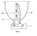
- FIG. 3 shows a lamp 20 inserted in the socket 1.
- the lamp base 21 lies on the plane formed by the covers 16 and 17, which enables a good adjustment of the lamp 20 in the reflector 22 of a lamp or in an optical system.
- the version described here is preferably intended for a metal halide high-pressure discharge lamp, although high-pressure discharge lamps without halide additives or noble gas lamps can also be used.
- the lamp is operated in particular at a square-wave voltage with an open-circuit voltage of more than 250 V, which makes the arrangement particularly suitable for film and television recordings without flicker effect.
- An ignition voltage of up to 25 kV is required for lamp ignition, especially for immediate re-ignition.
- the contact elements 8 and 9 of this version 1 are securely insulated against this high ignition voltage, so that flashovers cannot occur. Because of the small version and with it interacting lamp results in a robust, compact luminaire construction, easy lamp replacement and good focusability of the lamp light within the luminaire.
Landscapes
- Common Detailed Techniques For Electron Tubes Or Discharge Tubes (AREA)
- Connecting Device With Holders (AREA)
- Fastening Of Light Sources Or Lamp Holders (AREA)
Applications Claiming Priority (2)
| Application Number | Priority Date | Filing Date | Title |
|---|---|---|---|
| DE3412461 | 1984-04-03 | ||
| DE19843412461 DE3412461A1 (de) | 1984-04-03 | 1984-04-03 | Fassung fuer eine einseitig gesockelte hochdruckentladungslampe |
Publications (2)
| Publication Number | Publication Date |
|---|---|
| EP0157358A2 true EP0157358A2 (fr) | 1985-10-09 |
| EP0157358A3 EP0157358A3 (fr) | 1987-02-04 |
Family
ID=6232526
Family Applications (1)
| Application Number | Title | Priority Date | Filing Date |
|---|---|---|---|
| EP85103647A Ceased EP0157358A3 (fr) | 1984-04-03 | 1985-03-27 | Monture pour une lampe à décharge à haute pression à culot d'un côté |
Country Status (4)
| Country | Link |
|---|---|
| US (1) | US4741712A (fr) |
| EP (1) | EP0157358A3 (fr) |
| JP (1) | JPS60227377A (fr) |
| DE (1) | DE3412461A1 (fr) |
Cited By (3)
| Publication number | Priority date | Publication date | Assignee | Title |
|---|---|---|---|---|
| GB2234628A (en) * | 1989-07-31 | 1991-02-06 | Koito Mfg Co Ltd | Discharge lamp base construction. |
| EP0923105A1 (fr) * | 1997-12-11 | 1999-06-16 | Patent-Treuhand-Gesellschaft für elektrische Glühlampen mbH | Lampe à décharge à basse pression de type compact |
| DE10048986A1 (de) * | 2000-09-27 | 2002-04-11 | Patent Treuhand Ges Fuer Elektrische Gluehlampen Mbh | Dielektrische Barrieren-Entladungslampe |
Families Citing this family (2)
| Publication number | Priority date | Publication date | Assignee | Title |
|---|---|---|---|---|
| DE9010572U1 (de) * | 1990-07-13 | 1990-10-04 | Patent-Treuhand-Gesellschaft für elektrische Glühlampen mbH, 81543 München | Fassung für eine einseitig gesockelte Hochdruckentladungslampe |
| US5207600A (en) * | 1990-09-28 | 1993-05-04 | U.S. Philips Corporation | Lampholder for a high-pressure gas discharge lamp |
Family Cites Families (9)
| Publication number | Priority date | Publication date | Assignee | Title |
|---|---|---|---|---|
| FR824165A (fr) * | 1936-07-09 | 1938-02-02 | Lampes Sa | Perfectionnements aux supports de lampes |
| US2941181A (en) * | 1957-03-05 | 1960-06-14 | United Carr Fastener Corp | Electrical socket assembly |
| DE1589118A1 (de) * | 1967-11-02 | 1970-03-26 | Fritz Consten | Klemmfassung fuer Gluehlampen |
| US3614710A (en) * | 1969-07-07 | 1971-10-19 | Berkey Colortran Mfg Inc | Bipost socket for luminaires |
| US3960278A (en) * | 1974-11-07 | 1976-06-01 | Burroughs Corporation | Lamp cap assembly |
| US3999095A (en) * | 1975-10-06 | 1976-12-21 | General Motors Corporation | Lamp socket and bulb assembly with side contacts |
| NL185114C (nl) * | 1980-06-04 | 1990-01-16 | Philips Nv | Lagedrukkwikdampontladingslamp. |
| GB2100503B (en) * | 1981-06-06 | 1985-05-30 | Emi Plc Thorn | Discharge lamps |
| DE3236462A1 (de) * | 1982-10-01 | 1984-04-05 | Patent-Treuhand-Gesellschaft für elektrische Glühlampen mbH, 8000 München | Hochdruckentladungslampe mit sockel und zugehoeriger fassung |
-
1984
- 1984-04-03 DE DE19843412461 patent/DE3412461A1/de not_active Withdrawn
-
1985
- 1985-03-27 EP EP85103647A patent/EP0157358A3/fr not_active Ceased
- 1985-04-02 JP JP60068622A patent/JPS60227377A/ja active Pending
-
1986
- 1986-10-31 US US06/924,109 patent/US4741712A/en not_active Expired - Fee Related
Cited By (4)
| Publication number | Priority date | Publication date | Assignee | Title |
|---|---|---|---|---|
| GB2234628A (en) * | 1989-07-31 | 1991-02-06 | Koito Mfg Co Ltd | Discharge lamp base construction. |
| GB2234628B (en) * | 1989-07-31 | 1994-03-09 | Koito Mfg Co Ltd | Discharge lamp base construction |
| EP0923105A1 (fr) * | 1997-12-11 | 1999-06-16 | Patent-Treuhand-Gesellschaft für elektrische Glühlampen mbH | Lampe à décharge à basse pression de type compact |
| DE10048986A1 (de) * | 2000-09-27 | 2002-04-11 | Patent Treuhand Ges Fuer Elektrische Gluehlampen Mbh | Dielektrische Barrieren-Entladungslampe |
Also Published As
| Publication number | Publication date |
|---|---|
| EP0157358A3 (fr) | 1987-02-04 |
| JPS60227377A (ja) | 1985-11-12 |
| US4741712A (en) | 1988-05-03 |
| DE3412461A1 (de) | 1985-10-10 |
Similar Documents
| Publication | Publication Date | Title |
|---|---|---|
| EP0157357B1 (fr) | Lampe à décharge à haute pression à culot d'un côté | |
| DE3236462A1 (de) | Hochdruckentladungslampe mit sockel und zugehoeriger fassung | |
| DE3210005A1 (de) | Kompakte fluoreszenzlampe | |
| WO1998040936A1 (fr) | Lampe a halogene avec douille | |
| DE10200831A1 (de) | Lampe und Scheinwerfer zur einfachen Montage | |
| DE19857802A1 (de) | Kompakte Leuchtstofflampe mit internen Verbindungen | |
| DE69301406T2 (de) | Gesockelte elektrische Lampe und Verbindungselement dazu | |
| DE102013012310A1 (de) | Befestigungssystem zum Versiegeln und Ausrichten des Brenners der Lampe an der Mitte ihres Sockels | |
| EP0157358A2 (fr) | Monture pour une lampe à décharge à haute pression à culot d'un côté | |
| EP0012234A1 (fr) | Armature à lampe fluorescente | |
| EP0477663A1 (fr) | Pièce de contact | |
| DE69323157T2 (de) | Lampenfassung | |
| DE9010572U1 (de) | Fassung für eine einseitig gesockelte Hochdruckentladungslampe | |
| DE102008028383B4 (de) | Elektrische Lampe mit einem Außenkolben und einer Einbaulampe | |
| EP0784332A1 (fr) | Lampe à décharge à basse pression à culot unique et douille correspondante | |
| DE8812467U1 (de) | Hochdruckentladungslampe | |
| DE3531072C2 (fr) | ||
| DE3313465A1 (de) | Druckknopfbetaetigter ueberstromschalter | |
| DE8410358U1 (de) | Fassung für eine einseitig gesockelte Hochdruckentladungslampe | |
| WO2000018194A1 (fr) | Dispositif d'eclairage | |
| EP0156291A2 (fr) | Lampe compacte fluorescente | |
| DE10019760A1 (de) | Glühlampe mit Sockel | |
| EP0738026A1 (fr) | Ressort de contact | |
| DE3908618C2 (fr) | ||
| DE8812466U1 (de) | Fassung für eine einseitig gesockelte Hochdruckentladungslampe |
Legal Events
| Date | Code | Title | Description |
|---|---|---|---|
| PUAI | Public reference made under article 153(3) epc to a published international application that has entered the european phase |
Free format text: ORIGINAL CODE: 0009012 |
|
| AK | Designated contracting states |
Designated state(s): DE FR GB IT |
|
| PUAL | Search report despatched |
Free format text: ORIGINAL CODE: 0009013 |
|
| AK | Designated contracting states |
Kind code of ref document: A3 Designated state(s): DE FR GB IT |
|
| 17P | Request for examination filed |
Effective date: 19870309 |
|
| 17Q | First examination report despatched |
Effective date: 19880713 |
|
| STAA | Information on the status of an ep patent application or granted ep patent |
Free format text: STATUS: THE APPLICATION HAS BEEN REFUSED |
|
| 18R | Application refused |
Effective date: 19890407 |
|
| RIN1 | Information on inventor provided before grant (corrected) |
Inventor name: GREILER, WOLFGANG |