EP0923105A1 - Lampe à décharge à basse pression de type compact - Google Patents
Lampe à décharge à basse pression de type compact Download PDFInfo
- Publication number
- EP0923105A1 EP0923105A1 EP98121414A EP98121414A EP0923105A1 EP 0923105 A1 EP0923105 A1 EP 0923105A1 EP 98121414 A EP98121414 A EP 98121414A EP 98121414 A EP98121414 A EP 98121414A EP 0923105 A1 EP0923105 A1 EP 0923105A1
- Authority
- EP
- European Patent Office
- Prior art keywords
- pressure discharge
- discharge lamp
- low
- lamp according
- mounting plate
- Prior art date
- Legal status (The legal status is an assumption and is not a legal conclusion. Google has not performed a legal analysis and makes no representation as to the accuracy of the status listed.)
- Granted
Links
- 239000004020 conductor Substances 0.000 claims description 3
- 239000002184 metal Substances 0.000 claims description 3
- 238000005476 soldering Methods 0.000 claims description 3
- 229910000639 Spring steel Inorganic materials 0.000 claims description 2
- 239000002131 composite material Substances 0.000 claims description 2
- 229910001092 metal group alloy Inorganic materials 0.000 claims description 2
- 238000004519 manufacturing process Methods 0.000 description 13
- 239000011324 bead Substances 0.000 description 2
- 208000034656 Contusions Diseases 0.000 description 1
- 238000010276 construction Methods 0.000 description 1
- 210000003746 feather Anatomy 0.000 description 1
- 230000000284 resting effect Effects 0.000 description 1
Images

Classifications
-
- H—ELECTRICITY
- H01—ELECTRIC ELEMENTS
- H01J—ELECTRIC DISCHARGE TUBES OR DISCHARGE LAMPS
- H01J5/00—Details relating to vessels or to leading-in conductors common to two or more basic types of discharge tubes or lamps
- H01J5/50—Means forming part of the tube or lamps for the purpose of providing electrical connection to it
- H01J5/54—Means forming part of the tube or lamps for the purpose of providing electrical connection to it supported by a separate part, e.g. base
Definitions
- the invention relates to a compact low-pressure discharge lamp from a discharge vessel with electrodes and power supplies and a cap, housing and mounting plate with ballast arrangement composite base, the mounting plate with the ballast assembly is attached inside the base housing and connections for the electrical connection of the power supply lines to the mounting plate having.
- Known low-pressure discharge lamps are increasingly replacing them Incandescent lamp in the house and living area.
- the discharge vessel usually consists of a single or multiply bent tube, which is arranged in a base.
- the base In the base is a mounting plate designed as a circuit board with a electronic ballast assembly soldered to it integrated.
- the manufacturing cost for these compact low pressure discharge lamps are relative high, since many complicated manufacturing steps are required in the manufacture are.
- One of these manufacturing steps is the electrical connection the power supply lines of the discharge vessel with the corresponding connections the ballast arrangement. To make this connection previously merged the corresponding connecting wires and for example crimped with a metal sleeve.
- EP-A-0 452,743 discloses a low pressure discharge lamp of the type described above, which has retaining pins with whose help the ends of the power leads perpendicular to the bow-shaped Leads of the ballast are aligned.
- the respective wires to be contacted are approximately at right angles arranged one behind the other and with the help of the retaining pin and the inner wall of the base housing resiliently pressed against each other, so that an electrical Connection between the electrodes of the discharge vessel Ballast arrangement is made.
- a compact low-pressure discharge lamp the power supply lines of a discharge vessel with the electrical connections a mounting plate with ballast arrangement via a spring element, which pushes the power supply connected to the connector.
- a spring element which pressure on the power supply exerts a secure contact is guaranteed.
- advantageously only one element is used for the connection the power supply lines of the discharge vessel with the corresponding ones Connections to the mounting plate or the ballast required. This significantly reduces the manufacturing costs. It also results this advantageously results in a significant increase in the production speed, because when assembling the base of the low pressure discharge lamp Base housing and base cap just pressed together Need to become.
- the spring element Before assembling the base, the spring element is inventively received in a spring receptacle formed on the inner circumference of the cap.
- the spring receptacle has a cavity for receiving it from at least part of the spring element and is usually rectangular in cross section. This allows the spring elements regardless of the final assembly of the lamp, resulting in a Simplification of the manufacturing process contributes and thus the manufacturing costs lowers.
- the low-pressure discharge lamp according to the invention is a shoulder in the cavity of the spring holder designed to support an area of the spring element.
- a shoulder in the cavity of the spring holder designed to support an area of the spring element.
- the inner circumference of the housing and the outer circumference of the Cap formed a gap for receiving one end of the power supply.
- these features also contribute to simplifying the manufacturing process the lamp.
- the mounting plate perpendicular to the lamp's longitudinal axis attached inside the case.
- the mounting plate is there on ribs formed on the inner circumference of the housing, which are parallel to Lamp longitudinal axis run on.
- the mounting plate is advantageous formed as a circuit board, the one facing the discharge vessel Conductor side and on the side facing away from the discharge vessel Circuit elements of the ballast arrangement are formed. It is at least one connection for electrical contacting of the power supply trained with the mounting plate as a pad.
- In another advantageous Training has at least one connection to electrical Contacting the power supply with the mounting plate from one or several flat soldering areas and / or strips.
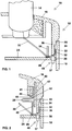
- FIG. 1 and Figure 2 is a schematically shown sectional view of a Compact low-pressure discharge lamp 10 according to the invention or one Portion of the edge region of the base 12 reproduced.
- the lamp 10 includes a discharge vessel 14 and a base 12, the base 12 is composed of a cap 16 and a housing 18.
- the base 12 is essentially cylindrical.
- the cap 16 and the housing 18 are releasably connected to each other, at least a positioning device 48 for connecting the cap 16 in the correct position and the housing 18 is formed.
- the cap 16 has the Housing 18 facing end of an annular bead 20 in its outer periphery on.
- the bead 20 and an annular groove 22 in the inner circumference of the housing 18 form a gap 34 for receiving an end 32 of a power supply 30 out.
- the mounting plate 24 is designed as a circuit board, on which the discharge vessel 14 facing conductor tracks and on the discharge vessel 14 opposite side circuit elements of the ballast arrangement (not shown) are trained.
- the discharge vessel 14 usually consists of two or three U-shaped bent pipe sections, which are connected to each other by a passage are (not shown), the end legs each carrying electrodes.
- the free ends of the pipe sections are sealed gas-tight by crushing and sit inside the cap 16 of the base 12.
- the current leads 30 are against the by means of a spring element 28 electrical connections 26 of the mounting plate 24 pressed.
- the spring element 28 engages in a formed in the region of the inner circumference of the cap 16
- Spring receptacle 40 and is in the embodiment shown detachably fastened in it.
- the spring receptacle 40 consists of side walls 41, 43, which surround a cavity 42.
- the cavity 42 is used for receiving a part of the spring element 28 and is rectangular in cross section educated.
- a shoulder 44 for supporting an area 50 of the Spring element 28 formed.
- the side walls surrounding cavity 42 41, 43 point towards the free end of the spring receptacle 40 46 on. These bevels 46 facilitate the introduction of the spring element 28.
- Gap 34 placed and thus aligned in the correct position.
- the mounting plate 24 has on the discharge vessel 14 facing Page connections 26 for electrical contacting of the power supplies 30 of the ballast arrangement.
- the connections 26 can be used as a pad or also as flat soldering surfaces integrated or resting in the mounting plate 24 and / or strips.
- FIG. 2 shows a sectional view of a partial area of the edge area of the Base 12. It can be seen that the free end of the housing 18 with the free End of the cap 16 is connected. In the area of the inner circumference of the cap 16, the spring holder 40 is formed. Surround the side walls 41, 43 the cavity 42 in the on the facing in the outer periphery of the cap 16 Page the shoulder 44 is formed. The spring holder 40 is in the Cross-section essentially rectangular. You can also see the bevel 46 of the side walls 41, 43. Also the different overall lengths the two side walls 41, 43 are clearly visible.
- a circumferential tab 36 forms the end of the cap 16 in the direction the mounting plate 24.
- the tab 36 forms at predetermined locations thorn-like extensions 37, which in corresponding recesses 38 of the Engage mounting plate 24.
- the thorn-like extensions 37 of the tab 36 and the recesses 38 thus form the positioning device 48.
- FIG. 3 shows a top view of a part of the edge area of the base 12 of FIG Lamp 10. It can be seen that the ends 32 of the power leads 30 in the between the circumferential tab 36 and the inner circumference of the housing 18 formed gap 34 comes to rest.
- the Power supply lines 30 below the spring element 28 are on the outer circumference the cap 16 in the area of the spring receptacles 40 each recesses 52 designed to receive the ends 32 of the power supply lines 30.
- Figure 4 shows a schematic representation of the design of the spring element 28.
- the spring element 28 is a multi-curved spring steel strip shown.
- the length of the spring element 28 is chosen such that that a reliable contact between the power supply 30 and the Connection 26 of the mounting plate 24 is guaranteed.
- the spring element 28 consists of plastic and / or metal and / or a metal alloy.
- the spring element can in a further embodiment, not shown be designed as a spiral spring. Any other advantageous feather shape is conceivable.
Landscapes
- Vessels And Coating Films For Discharge Lamps (AREA)
- Common Detailed Techniques For Electron Tubes Or Discharge Tubes (AREA)
- Fastening Of Light Sources Or Lamp Holders (AREA)
- Securing Globes, Refractors, Reflectors Or The Like (AREA)
- Non-Portable Lighting Devices Or Systems Thereof (AREA)
Applications Claiming Priority (2)
| Application Number | Priority Date | Filing Date | Title |
|---|---|---|---|
| DE19755171 | 1997-12-11 | ||
| DE19755171A DE19755171A1 (de) | 1997-12-11 | 1997-12-11 | Kompakte Niederdruckentladungslampe |
Publications (2)
| Publication Number | Publication Date |
|---|---|
| EP0923105A1 true EP0923105A1 (fr) | 1999-06-16 |
| EP0923105B1 EP0923105B1 (fr) | 2003-01-29 |
Family
ID=7851625
Family Applications (1)
| Application Number | Title | Priority Date | Filing Date |
|---|---|---|---|
| EP98121414A Expired - Lifetime EP0923105B1 (fr) | 1997-12-11 | 1998-11-11 | Lampe à décharge à basse pression de type compact |
Country Status (7)
| Country | Link |
|---|---|
| US (1) | US6239540B1 (fr) |
| EP (1) | EP0923105B1 (fr) |
| JP (1) | JP4221095B2 (fr) |
| KR (1) | KR100602391B1 (fr) |
| CN (1) | CN1149608C (fr) |
| CA (1) | CA2255177C (fr) |
| DE (2) | DE19755171A1 (fr) |
Cited By (2)
| Publication number | Priority date | Publication date | Assignee | Title |
|---|---|---|---|---|
| WO2013160784A1 (fr) * | 2012-04-26 | 2013-10-31 | Koninklijke Philips N.V. | Lampe à décharge à voies de contact à l'intérieur de la base |
| US9123498B2 (en) | 2012-04-26 | 2015-09-01 | Koninklijke Philips N.V. | Ground connection to a lamp housing |
Families Citing this family (3)
| Publication number | Priority date | Publication date | Assignee | Title |
|---|---|---|---|---|
| US7514872B2 (en) * | 2005-09-08 | 2009-04-07 | Osram Sylvania Inc. | Reflector lamp with engaging electrical contact |
| CN102062368B (zh) * | 2010-09-28 | 2013-07-31 | 上海亚明灯泡厂有限公司 | 替换支架灯灯管及灯头盖 |
| CN105225768B (zh) * | 2015-10-12 | 2017-03-01 | 中北大学 | 一种三明治结构柔性镀银功能粒子导电膜的制备方法 |
Citations (9)
| Publication number | Priority date | Publication date | Assignee | Title |
|---|---|---|---|---|
| DE631652C (de) * | 1935-04-02 | 1936-06-29 | Alfred Mendel | Kontaktelement fuer Roehrensockel, insbesondere Radioroehrensockel |
| DD145143A1 (de) * | 1979-07-13 | 1980-11-19 | Reinhard Butz | Sockelbodenkontaktierung zwischen odenkontaktstueck und stromzufuehrungsdraht einer elekt ischen lampe |
| EP0157358A2 (fr) * | 1984-04-03 | 1985-10-09 | Patent-Treuhand-Gesellschaft für elektrische Glühlampen mbH | Monture pour une lampe à décharge à haute pression à culot d'un côté |
| EP0179473A2 (fr) * | 1984-10-25 | 1986-04-30 | Patent-Treuhand-Gesellschaft für elektrische Glühlampen mbH | Adaptateur pour une lampe à décharge à basse pression à culot unique |
| EP0179251A2 (fr) * | 1984-10-25 | 1986-04-30 | Patent-Treuhand-Gesellschaft für elektrische Glühlampen mbH | Lampe à décharge à vapeur de mercure à basse pression avec culot unique |
| EP0349083A1 (fr) * | 1988-07-01 | 1990-01-03 | Koninklijke Philips Electronics N.V. | Lampe électrique |
| EP0452743A1 (fr) * | 1990-04-20 | 1991-10-23 | Patent-Treuhand-Gesellschaft für elektrische Glühlampen mbH | Lampe à décharge compacte à basse pression |
| DE9213547U1 (de) * | 1991-10-23 | 1992-12-10 | Oshino Lamps GmbH, 8500 Nürnberg | Glühlampenfassung mit Glühlampe(n) |
| EP0813354A1 (fr) * | 1996-06-15 | 1997-12-17 | Sung-Ho Cho | Adaptateur pour lampe fluorescente compacte |
Family Cites Families (4)
| Publication number | Priority date | Publication date | Assignee | Title |
|---|---|---|---|---|
| HU214132B (en) * | 1994-01-25 | 1997-12-29 | Ge Lighting Tungsram Rt | Discharge lamp having its cap at one side |
| JPH09306203A (ja) * | 1996-05-10 | 1997-11-28 | Koito Mfg Co Ltd | 放電灯バルブ用ソケット |
| DE19701162A1 (de) * | 1997-01-15 | 1998-07-16 | Patent Treuhand Ges Fuer Elektrische Gluehlampen Mbh | Kompakte Niederdruckentladungslampe |
| DE19709928A1 (de) * | 1997-03-11 | 1998-09-17 | Patent Treuhand Ges Fuer Elektrische Gluehlampen Mbh | Halogenglühlampe und Fassung |
-
1997
- 1997-12-11 DE DE19755171A patent/DE19755171A1/de not_active Withdrawn
-
1998
- 1998-11-11 DE DE59807060T patent/DE59807060D1/de not_active Expired - Fee Related
- 1998-11-11 CN CNB981242111A patent/CN1149608C/zh not_active Expired - Fee Related
- 1998-11-11 EP EP98121414A patent/EP0923105B1/fr not_active Expired - Lifetime
- 1998-12-03 CA CA002255177A patent/CA2255177C/fr not_active Expired - Fee Related
- 1998-12-08 US US09/207,866 patent/US6239540B1/en not_active Expired - Fee Related
- 1998-12-08 JP JP34868898A patent/JP4221095B2/ja not_active Expired - Fee Related
- 1998-12-11 KR KR1019980054320A patent/KR100602391B1/ko not_active Expired - Fee Related
Patent Citations (9)
| Publication number | Priority date | Publication date | Assignee | Title |
|---|---|---|---|---|
| DE631652C (de) * | 1935-04-02 | 1936-06-29 | Alfred Mendel | Kontaktelement fuer Roehrensockel, insbesondere Radioroehrensockel |
| DD145143A1 (de) * | 1979-07-13 | 1980-11-19 | Reinhard Butz | Sockelbodenkontaktierung zwischen odenkontaktstueck und stromzufuehrungsdraht einer elekt ischen lampe |
| EP0157358A2 (fr) * | 1984-04-03 | 1985-10-09 | Patent-Treuhand-Gesellschaft für elektrische Glühlampen mbH | Monture pour une lampe à décharge à haute pression à culot d'un côté |
| EP0179473A2 (fr) * | 1984-10-25 | 1986-04-30 | Patent-Treuhand-Gesellschaft für elektrische Glühlampen mbH | Adaptateur pour une lampe à décharge à basse pression à culot unique |
| EP0179251A2 (fr) * | 1984-10-25 | 1986-04-30 | Patent-Treuhand-Gesellschaft für elektrische Glühlampen mbH | Lampe à décharge à vapeur de mercure à basse pression avec culot unique |
| EP0349083A1 (fr) * | 1988-07-01 | 1990-01-03 | Koninklijke Philips Electronics N.V. | Lampe électrique |
| EP0452743A1 (fr) * | 1990-04-20 | 1991-10-23 | Patent-Treuhand-Gesellschaft für elektrische Glühlampen mbH | Lampe à décharge compacte à basse pression |
| DE9213547U1 (de) * | 1991-10-23 | 1992-12-10 | Oshino Lamps GmbH, 8500 Nürnberg | Glühlampenfassung mit Glühlampe(n) |
| EP0813354A1 (fr) * | 1996-06-15 | 1997-12-17 | Sung-Ho Cho | Adaptateur pour lampe fluorescente compacte |
Cited By (3)
| Publication number | Priority date | Publication date | Assignee | Title |
|---|---|---|---|---|
| WO2013160784A1 (fr) * | 2012-04-26 | 2013-10-31 | Koninklijke Philips N.V. | Lampe à décharge à voies de contact à l'intérieur de la base |
| US9123498B2 (en) | 2012-04-26 | 2015-09-01 | Koninklijke Philips N.V. | Ground connection to a lamp housing |
| US9414473B2 (en) | 2012-04-26 | 2016-08-09 | Koninklijke Philips N.V. | Discharge lamp with contact paths within the base |
Also Published As
| Publication number | Publication date |
|---|---|
| DE59807060D1 (de) | 2003-03-06 |
| KR100602391B1 (ko) | 2007-08-16 |
| JP4221095B2 (ja) | 2009-02-12 |
| CA2255177A1 (fr) | 1999-06-11 |
| JPH11250726A (ja) | 1999-09-17 |
| CA2255177C (fr) | 2008-01-29 |
| DE19755171A1 (de) | 1999-06-17 |
| KR19990062985A (ko) | 1999-07-26 |
| CN1149608C (zh) | 2004-05-12 |
| EP0923105B1 (fr) | 2003-01-29 |
| CN1219746A (zh) | 1999-06-16 |
| US6239540B1 (en) | 2001-05-29 |
Similar Documents
| Publication | Publication Date | Title |
|---|---|---|
| DE69303563T2 (de) | Lampe mit integriertem Elektronikmodul | |
| DE19912032C1 (de) | Strahlereinheit aus beidseitig gesockelter Entladungslampe und Lampen-Fassung | |
| EP0452743A1 (fr) | Lampe à décharge compacte à basse pression | |
| DE102017125505A1 (de) | Steckerbuchse für Leiterplatinen | |
| DE3912189A1 (de) | Schutzleiterverbindung | |
| EP0854497B1 (fr) | Lampe compacte à décharge basse pression | |
| DE2952535A1 (de) | Entladungslampe | |
| EP0854496B1 (fr) | Lampe compacte à décharge basse pression | |
| DE2803462C2 (de) | Leuchtstofflampe | |
| EP0923105A1 (fr) | Lampe à décharge à basse pression de type compact | |
| EP0319633B1 (fr) | Connecteur cinch | |
| DE60034284T2 (de) | Lampe mit Schraubsockel und im Sockelgehäuse enthaltene Elektronik, sowie Verfahren zur deren Herstellung | |
| DE69118123T2 (de) | Signallampe und Verfahren zur Herstellung derselben | |
| DE2439249A1 (de) | Gluehlampe und sockel | |
| EP2200125A2 (fr) | Connecteur à fiches blindé | |
| DE60037175T2 (de) | Niederdruck gasentladungslampe | |
| DE3908618C2 (fr) | ||
| DE19509112A1 (de) | Kompaktleuchtstofflampe mit kreisrundem Gasentladungsgefäß | |
| DE3531072C2 (fr) | ||
| EP1329932B1 (fr) | Lampe compacte à décharge à basse pression | |
| DE19757783A1 (de) | Einendige Entladungslampe | |
| DE2018702B2 (de) | Elektrische Lampe mit einem Lampensockel aus Kunststoff | |
| DE19805258C2 (de) | Lampenfassung | |
| DE3512712C2 (fr) | ||
| DE10000245B4 (de) | Lampenfassung |
Legal Events
| Date | Code | Title | Description |
|---|---|---|---|
| PUAI | Public reference made under article 153(3) epc to a published international application that has entered the european phase |
Free format text: ORIGINAL CODE: 0009012 |
|
| AK | Designated contracting states |
Kind code of ref document: A1 Designated state(s): BE DE FR GB IT NL |
|
| AX | Request for extension of the european patent |
Free format text: AL;LT;LV;MK;RO;SI |
|
| 17P | Request for examination filed |
Effective date: 19990706 |
|
| AKX | Designation fees paid |
Free format text: BE DE FR GB IT NL |
|
| 17Q | First examination report despatched |
Effective date: 20010309 |
|
| GRAG | Despatch of communication of intention to grant |
Free format text: ORIGINAL CODE: EPIDOS AGRA |
|
| GRAG | Despatch of communication of intention to grant |
Free format text: ORIGINAL CODE: EPIDOS AGRA |
|
| GRAH | Despatch of communication of intention to grant a patent |
Free format text: ORIGINAL CODE: EPIDOS IGRA |
|
| GRAH | Despatch of communication of intention to grant a patent |
Free format text: ORIGINAL CODE: EPIDOS IGRA |
|
| GRAA | (expected) grant |
Free format text: ORIGINAL CODE: 0009210 |
|
| AK | Designated contracting states |
Designated state(s): BE DE FR GB IT NL |
|
| REG | Reference to a national code |
Ref country code: GB Ref legal event code: FG4D Free format text: NOT ENGLISH |
|
| REF | Corresponds to: |
Ref document number: 59807060 Country of ref document: DE Date of ref document: 20030306 Kind code of ref document: P |
|
| GBT | Gb: translation of ep patent filed (gb section 77(6)(a)/1977) |
Effective date: 20030501 |
|
| ET | Fr: translation filed | ||
| PLBE | No opposition filed within time limit |
Free format text: ORIGINAL CODE: 0009261 |
|
| STAA | Information on the status of an ep patent application or granted ep patent |
Free format text: STATUS: NO OPPOSITION FILED WITHIN TIME LIMIT |
|
| 26N | No opposition filed |
Effective date: 20031030 |
|
| PGFP | Annual fee paid to national office [announced via postgrant information from national office to epo] |
Ref country code: NL Payment date: 20081111 Year of fee payment: 11 |
|
| PGFP | Annual fee paid to national office [announced via postgrant information from national office to epo] |
Ref country code: IT Payment date: 20081126 Year of fee payment: 11 Ref country code: BE Payment date: 20081119 Year of fee payment: 11 |
|
| PGFP | Annual fee paid to national office [announced via postgrant information from national office to epo] |
Ref country code: FR Payment date: 20081118 Year of fee payment: 11 |
|
| PGFP | Annual fee paid to national office [announced via postgrant information from national office to epo] |
Ref country code: DE Payment date: 20090119 Year of fee payment: 11 |
|
| PGFP | Annual fee paid to national office [announced via postgrant information from national office to epo] |
Ref country code: GB Payment date: 20081110 Year of fee payment: 11 |
|
| BERE | Be: lapsed |
Owner name: *PATENT-TREUHAND-G.- FUR ELEKTRISCHE GLUHLAMPEN M. Effective date: 20091130 |
|
| REG | Reference to a national code |
Ref country code: NL Ref legal event code: V1 Effective date: 20100601 |
|
| GBPC | Gb: european patent ceased through non-payment of renewal fee |
Effective date: 20091111 |
|
| REG | Reference to a national code |
Ref country code: FR Ref legal event code: ST Effective date: 20100730 |
|
| PG25 | Lapsed in a contracting state [announced via postgrant information from national office to epo] |
Ref country code: NL Free format text: LAPSE BECAUSE OF NON-PAYMENT OF DUE FEES Effective date: 20100601 Ref country code: FR Free format text: LAPSE BECAUSE OF NON-PAYMENT OF DUE FEES Effective date: 20091130 Ref country code: BE Free format text: LAPSE BECAUSE OF NON-PAYMENT OF DUE FEES Effective date: 20091130 |
|
| PG25 | Lapsed in a contracting state [announced via postgrant information from national office to epo] |
Ref country code: DE Free format text: LAPSE BECAUSE OF NON-PAYMENT OF DUE FEES Effective date: 20100601 |
|
| PG25 | Lapsed in a contracting state [announced via postgrant information from national office to epo] |
Ref country code: GB Free format text: LAPSE BECAUSE OF NON-PAYMENT OF DUE FEES Effective date: 20091111 |
|
| PG25 | Lapsed in a contracting state [announced via postgrant information from national office to epo] |
Ref country code: IT Free format text: LAPSE BECAUSE OF NON-PAYMENT OF DUE FEES Effective date: 20091111 |