EP0784332A1 - Lampe à décharge à basse pression à culot unique et douille correspondante - Google Patents
Lampe à décharge à basse pression à culot unique et douille correspondante Download PDFInfo
- Publication number
- EP0784332A1 EP0784332A1 EP97100073A EP97100073A EP0784332A1 EP 0784332 A1 EP0784332 A1 EP 0784332A1 EP 97100073 A EP97100073 A EP 97100073A EP 97100073 A EP97100073 A EP 97100073A EP 0784332 A1 EP0784332 A1 EP 0784332A1
- Authority
- EP
- European Patent Office
- Prior art keywords
- base
- socket
- lamp
- contacts
- low
- Prior art date
- Legal status (The legal status is an assumption and is not a legal conclusion. Google has not performed a legal analysis and makes no representation as to the accuracy of the status listed.)
- Granted
Links
Images


Classifications
-
- H—ELECTRICITY
- H01—ELECTRIC ELEMENTS
- H01J—ELECTRIC DISCHARGE TUBES OR DISCHARGE LAMPS
- H01J61/00—Gas-discharge or vapour-discharge lamps
- H01J61/02—Details
- H01J61/30—Vessels; Containers
- H01J61/32—Special longitudinal shape, e.g. for advertising purposes
- H01J61/322—Circular lamps
-
- H—ELECTRICITY
- H01—ELECTRIC ELEMENTS
- H01J—ELECTRIC DISCHARGE TUBES OR DISCHARGE LAMPS
- H01J61/00—Gas-discharge or vapour-discharge lamps
- H01J61/02—Details
- H01J61/30—Vessels; Containers
- H01J61/32—Special longitudinal shape, e.g. for advertising purposes
-
- H—ELECTRICITY
- H01—ELECTRIC ELEMENTS
- H01J—ELECTRIC DISCHARGE TUBES OR DISCHARGE LAMPS
- H01J5/00—Details relating to vessels or to leading-in conductors common to two or more basic types of discharge tubes or lamps
- H01J5/50—Means forming part of the tube or lamps for the purpose of providing electrical connection to it
- H01J5/54—Means forming part of the tube or lamps for the purpose of providing electrical connection to it supported by a separate part, e.g. base
- H01J5/56—Shape of the separate part
- H01J5/565—Bases for circular lamps
Definitions
- the invention relates to a low-pressure discharge lamp with a base on one side and an associated version according to the preamble of claim 9.
- Such lamps are characterized by their rather flat shape.
- a tubular discharge vessel with a typically circular cross section is arranged in one plane in such a way that the two ends of the discharge vessel face each other.
- the ring shape is particularly common. Due to the associated circular symmetrical radiation characteristics, it is particularly suitable for general lighting, e.g. in living and office spaces.
- the lamp is usually built into a luminaire, which may also include an optical reflector for light control.
- the current leads of the electrodes arranged inside the vessel are led gas-tight to the outside through the ends of the discharge vessel.
- the two ends of the vessel, including power supplies, are surrounded by a common elongated base.
- the power leads are connected to electrical contacts on the base.
- the base contacts are used to make contact with the corresponding contacts of a lamp holder.
- a ring-shaped fluorescent lamp (e.g. OSRAM L32 / 41-827C with base G10q) is known in which the pin-shaped base contacts are arranged square at an angle of 45 ° with respect to the ring plane of the lamp.
- Another disadvantage is the relatively voluminous base, which opposes efforts towards compact, in particular flat, luminaires.
- the object of the invention is to eliminate the above-mentioned defects and to provide a low-pressure discharge lamp of the type explained at the beginning, which has a compact, flat and simply designed base, which enables simple and quick lamp installation and, if appropriate, fitting a lamp.
- Another object of the invention is to provide a version associated with the base according to the invention.
- the basic idea of the invention is to arrange the base contacts essentially in the plane in which the discharge vessel extends, one half of the base contacts being arranged on a first side of the base and the other half on the opposite side of the base.
- the two base contacts of each lamp end are preferably arranged on the opposite sides of the base.
- the base according to the invention is characterized by a particularly low overall height.
- This base is particularly advantageously used with discharge tubes with particularly small diameters (typically 16 mm instead of the previously customary 30 mm). This has the advantage that the entire arrangement of lamp with base is relatively flat.
- the associated version has a channel-like opening for receiving the base.
- the two side walls of the opening are each provided with two slot-like recesses for receiving the base contacts.
- Contacts are arranged in the cutouts. When inserting the base into the socket, the associated contacts touch each other, thus ensuring contact between the base and socket.
- the advantage of this solution is that only a single straight-line movement is required for the lighting equipment.
- the socket contacts in the cutouts which are usually at an increased electrical potential with respect to the environment, are protected against accidental contact.
- the base according to the invention has an elongated, cylinder-like basic shape which is open on the two end faces.
- the circular openings in the base serve to receive the two ends of the discharge vessel, including the associated power supply lines.
- Two pin-shaped contacts each protrude from two opposite sides of the central cuboid part of the base.
- the contacts are arranged in the plane in which the discharge vessel extends.
- Two contacts at a time - one contact from each of the two opposite sides - form a pair of contacts which are connected to the two power supply lines at each end of the vessel.
- the current leads in the common plane of the base contacts are preferably led outward from the discharge vessel. In this way, a particularly flat design can be realized without the power supply lines being able to touch one another.
- the associated version has a U-shape-like basic shape.
- the two legs of the socket each have two slot-like recesses with contacts. They are used to record and make contact with the corresponding socket contacts. To do this, the lamp base is inserted into the space between the legs.
- the socket contacts are designed as detent springs.
- the base contacts snap into the socket contacts.
- the socket contacts are used not only for making electrical contact but also for locking the base and consequently the lamp connected to the base in the socket.
- the locking is carried out by an additional fastening element.
- the two side walls of the channel-like opening are each provided with a nose-like retaining spring which, when connecting the base and socket m, engage corresponding recesses in the outer wall of the base.
- FIG. 1 the top view of a fluorescent lamp 1 according to the invention is shown schematically.
- the fluorescent lamp 1 consists, in a manner known per se, of an annular discharge tube 2 coated with a fluorescent material, in which two glow electrodes are arranged (not shown) and a base 3 with four pin-shaped base contacts (8a, 8b, 9a, 9b), in the latter projections 4.5 similar to a circular cylinder protrude the two ends of the discharge tube 2.
- the discharge tube 2 has a circular cross section with a diameter of approximately 16 mm.
- the base represents the actual innovation of the lamp and is therefore explained in more detail below.
- the same reference numerals designate the same features.
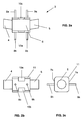
- Figures 2a to 2c show the top, side and end view of the base 3 of the fluorescent lamp 1 from Figure 1.
- the base 3 consists of a elongated, cuboid middle part 6 and the two circular cylinder-like extensions 4,5.
- the extensions 4, 5 are each formed obliquely on the two end faces of the central part 6 in order to be able to accommodate the two ends of the annular discharge tube 2, as indicated in FIG. 1.
- Two contact pins 8a, 9a and 8b, 9b each protrude from two opposite side walls 7a, b of the central part 6.
- Two contacts 8a, 8b and 9a, 9b - a contact from each of the two opposite side walls 7a, 7b - form a pair of contacts.
- the first contact pair 8a, 8b is connected to the two current leads of the first end of the discharge vessel 2 (not shown) and the other contact pair 9a, 9b to the current leads of the other end (not shown).
- the side walls 7a, b mentioned each have two rectangular cutouts 10a, 10b and 10c, 10d (the cutout 10d is covered in the illustration), each pair of cutouts 10a, 10b and 10c, 10d lying opposite one another in the region of the longitudinal edges is arranged.
- a recess 10a, 10c per side wall serves as a snap-in opening for corresponding retaining springs of the associated socket.
- the respective other recess 10b, 10d is used for locking when the base is rotated accordingly by 180 °.
- the longitudinal edges of the middle part 6 are provided with chamfers 11 in order to avoid tilting when inserting them into the lamp holder.
- FIGS. 3a and 3b show the top view or end view of a socket 12 belonging to the base from FIG. 1. It has a channel-like shape with a rectangular base and a U-shaped end view.
- the two legs 13a, 13b of the socket each have two slot-like recesses 14a, 15a and 14b, 15b with spring contacts 16a, 17a and 16b, 17b. They serve to receive and make contact with the corresponding pin contacts 8a, 9a and 8b, 9b of the base 3.
- the two side walls of the channel-like opening between the legs 13a, 13b are each provided with a nose-like retaining spring 18a, b.
- the lamp base 3 is inserted into the channel-like opening (not shown).
- the retaining springs 18a, b of the socket snap into the recesses 10a, 10b of the base 3.
Landscapes
- Vessels And Coating Films For Discharge Lamps (AREA)
- Common Detailed Techniques For Electron Tubes Or Discharge Tubes (AREA)
- Fastening Of Light Sources Or Lamp Holders (AREA)
- Connecting Device With Holders (AREA)
Applications Claiming Priority (2)
| Application Number | Priority Date | Filing Date | Title |
|---|---|---|---|
| DE29600594U DE29600594U1 (de) | 1996-01-15 | 1996-01-15 | Einseitig gesockelte Niederdruckentladungslampe und zugehörige Fassung |
| DE29600594U | 1996-01-15 |
Publications (2)
| Publication Number | Publication Date |
|---|---|
| EP0784332A1 true EP0784332A1 (fr) | 1997-07-16 |
| EP0784332B1 EP0784332B1 (fr) | 2000-11-29 |
Family
ID=8018041
Family Applications (1)
| Application Number | Title | Priority Date | Filing Date |
|---|---|---|---|
| EP97100073A Expired - Lifetime EP0784332B1 (fr) | 1996-01-15 | 1997-01-03 | Lampe à décharge à basse pression à culot unique et douille correspondante |
Country Status (6)
| Country | Link |
|---|---|
| US (1) | US5789849A (fr) |
| EP (1) | EP0784332B1 (fr) |
| JP (1) | JP3854354B2 (fr) |
| KR (1) | KR100442890B1 (fr) |
| DE (2) | DE29600594U1 (fr) |
| TR (1) | TR199700015A2 (fr) |
Families Citing this family (7)
| Publication number | Priority date | Publication date | Assignee | Title |
|---|---|---|---|---|
| JP3135526B2 (ja) * | 1997-03-31 | 2001-02-19 | 松下電子工業株式会社 | 環形蛍光ランプ |
| EP0935092A1 (fr) * | 1998-02-03 | 1999-08-11 | General Electric Company | Lampe à décharge à basse pression et support de lampe |
| JP2002324513A (ja) * | 2001-04-25 | 2002-11-08 | Nec Lighting Ltd | 環形蛍光ランプ及び照明器具 |
| JP4770595B2 (ja) * | 2006-06-05 | 2011-09-14 | パナソニック株式会社 | 環形蛍光ランプ |
| JP4666313B2 (ja) * | 2007-05-21 | 2011-04-06 | Necライティング株式会社 | ランプ |
| DE102008053623A1 (de) * | 2008-10-29 | 2010-05-12 | Osram Gesellschaft mit beschränkter Haftung | Leuchteinrichtung mit einer Entladungslampe und einem teilweise extern zur Entladungslampe angeordneten und mit dieser elektrisch verbundenen elektronischen Betriebsgerät |
| JP5557808B2 (ja) * | 2011-06-22 | 2014-07-23 | 日立アプライアンス株式会社 | 蛍光ランプ |
Citations (6)
| Publication number | Priority date | Publication date | Assignee | Title |
|---|---|---|---|---|
| CH270390A (de) * | 1948-12-11 | 1950-08-31 | Lumalampan Ab | Elektrische Gasentladungslampe, welche die Form einer in sich geschlossenen Schleife aufweist. |
| US2597666A (en) * | 1947-11-05 | 1952-05-20 | Gen Electric | Movable contact base |
| FR1157561A (fr) * | 1955-09-21 | 1958-05-30 | Lampes Sa | Appareil d'éclairage à lampe circulaire à fluorescence |
| JPS56106336A (en) * | 1980-01-26 | 1981-08-24 | Nec Home Electronics Ltd | Metallic piece for bulb |
| GB2137017A (en) * | 1983-03-02 | 1984-09-26 | Emi Plc Thorn | Improvements in or relating to discharge lamps |
| JPH04223083A (ja) * | 1990-12-26 | 1992-08-12 | Matsushita Electric Works Ltd | 丸型蛍光灯照明器具 |
Family Cites Families (27)
| Publication number | Priority date | Publication date | Assignee | Title |
|---|---|---|---|---|
| BE478359A (fr) * | 1941-10-18 | |||
| US2366252A (en) * | 1941-10-18 | 1945-01-02 | Gen Electric | Circular electric lamp |
| US2367984A (en) * | 1943-06-03 | 1945-01-23 | Bryant Electric Co | Discharge lamp assembly |
| US2392785A (en) * | 1945-03-28 | 1946-01-08 | Sylvania Electric Prod | Lamp base |
| US2453986A (en) * | 1945-05-07 | 1948-11-16 | Gen Electric | Circular electric lamp |
| US2413662A (en) * | 1945-08-21 | 1946-12-31 | Sylvania Electric Prod | Lamp base |
| US2480301A (en) * | 1946-02-01 | 1949-08-30 | Clayton M Moretz | Electric light fixture |
| US2733417A (en) * | 1952-10-30 | 1956-01-31 | Metal sleeve base for double ended tubular lamp | |
| US3292097A (en) * | 1963-12-16 | 1966-12-13 | Edwin S Gaynor | Circular fluorescent lamp connector |
| JPS4842373U (fr) * | 1971-09-20 | 1973-05-30 | ||
| US3752977A (en) * | 1972-04-20 | 1973-08-14 | Sola Basic Ind Inc | Adjustable fluorescent lamp mounting means |
| US3898495A (en) * | 1974-04-05 | 1975-08-05 | Westinghouse Electric Corp | Circular fluorescent lamp with two-piece snap-lock base |
| US4002394A (en) * | 1975-10-10 | 1977-01-11 | General Electric Company | Single latch snap-lock base for annular fluorescent lamps |
| US4468071A (en) * | 1981-02-18 | 1984-08-28 | General Electric Company | Double latch snap lock base for annular fluorescent lamps |
| JPS57179250U (fr) * | 1981-05-08 | 1982-11-13 | ||
| US4350400A (en) * | 1981-07-14 | 1982-09-21 | Gaynor Edwin S | Connector for circular fluorescent lamp |
| NL8402000A (nl) * | 1983-07-20 | 1985-02-18 | Kuiper Adrianus Maria | Lamphouder voor lus-, u- of pi-vormige gasontladings- of fluorescentielamp met een enkele lampvoet. |
| US4569004A (en) * | 1984-09-17 | 1986-02-04 | Peterson William A | Cove light fixture |
| JPS61153917A (ja) * | 1984-12-27 | 1986-07-12 | Toshiba Corp | 環形螢光ランプの口金 |
| JPS6210832A (ja) * | 1985-07-08 | 1987-01-19 | Toshiba Corp | 環形螢光ランプ用口金 |
| JPS6251129A (ja) * | 1985-08-28 | 1987-03-05 | Toshiba Corp | 環形螢光ランプ |
| JPS63198223A (ja) * | 1987-02-12 | 1988-08-16 | Hitachi Ltd | 環形蛍光ランプの口金 |
| US4771370A (en) * | 1987-06-29 | 1988-09-13 | Gte Products Corporation | Leg strap for U-shaped lamp |
| JPH01255126A (ja) * | 1988-04-04 | 1989-10-12 | Nec Home Electron Ltd | 放電灯及びその製造方法 |
| JPH0797477B2 (ja) * | 1988-09-22 | 1995-10-18 | 東芝ライテック株式会社 | 放電ランプ装置 |
| JPH0286025A (ja) * | 1988-09-20 | 1990-03-27 | Toshiba Lighting & Technol Corp | 環形ランプ装置 |
| JPH0772476A (ja) * | 1993-09-02 | 1995-03-17 | Harrison Denki Kk | 照明装置 |
-
1996
- 1996-01-15 DE DE29600594U patent/DE29600594U1/de not_active Expired - Lifetime
-
1997
- 1997-01-03 EP EP97100073A patent/EP0784332B1/fr not_active Expired - Lifetime
- 1997-01-03 DE DE59702675T patent/DE59702675D1/de not_active Expired - Lifetime
- 1997-01-08 JP JP1311297A patent/JP3854354B2/ja not_active Expired - Fee Related
- 1997-01-09 TR TR97/00015A patent/TR199700015A2/xx unknown
- 1997-01-14 US US08/783,251 patent/US5789849A/en not_active Expired - Lifetime
- 1997-01-15 KR KR1019970000982A patent/KR100442890B1/ko not_active Expired - Fee Related
Patent Citations (6)
| Publication number | Priority date | Publication date | Assignee | Title |
|---|---|---|---|---|
| US2597666A (en) * | 1947-11-05 | 1952-05-20 | Gen Electric | Movable contact base |
| CH270390A (de) * | 1948-12-11 | 1950-08-31 | Lumalampan Ab | Elektrische Gasentladungslampe, welche die Form einer in sich geschlossenen Schleife aufweist. |
| FR1157561A (fr) * | 1955-09-21 | 1958-05-30 | Lampes Sa | Appareil d'éclairage à lampe circulaire à fluorescence |
| JPS56106336A (en) * | 1980-01-26 | 1981-08-24 | Nec Home Electronics Ltd | Metallic piece for bulb |
| GB2137017A (en) * | 1983-03-02 | 1984-09-26 | Emi Plc Thorn | Improvements in or relating to discharge lamps |
| JPH04223083A (ja) * | 1990-12-26 | 1992-08-12 | Matsushita Electric Works Ltd | 丸型蛍光灯照明器具 |
Non-Patent Citations (2)
| Title |
|---|
| PATENT ABSTRACTS OF JAPAN vol. 005, no. 179 (E - 082) 17 November 1981 (1981-11-17) * |
| PATENT ABSTRACTS OF JAPAN vol. 016, no. 574 (E - 1298) 14 December 1992 (1992-12-14) * |
Also Published As
| Publication number | Publication date |
|---|---|
| US5789849A (en) | 1998-08-04 |
| EP0784332B1 (fr) | 2000-11-29 |
| JPH09199003A (ja) | 1997-07-31 |
| KR970060339A (ko) | 1997-08-12 |
| DE59702675D1 (de) | 2001-01-04 |
| DE29600594U1 (de) | 1997-05-07 |
| KR100442890B1 (ko) | 2004-09-18 |
| JP3854354B2 (ja) | 2006-12-06 |
| TR199700015A2 (tr) | 1997-08-21 |
Similar Documents
| Publication | Publication Date | Title |
|---|---|---|
| EP0784332B1 (fr) | Lampe à décharge à basse pression à culot unique et douille correspondante | |
| AT14622U1 (de) | Leuchte bzw. Beleuchtungsanordnung mit länglichem Trägerelement und lösbar befestigbarem Leuchtmodul | |
| EP1334510B1 (fr) | Lampe a decharge a barriere dielectrique | |
| DE3440748C2 (de) | Leitungssteckverbinder mit Bauelementeeinsatz | |
| EP0742610A2 (fr) | Lampe électrique à double culot ayant une position de travail préférée et un socle à douille associé | |
| DE2458360C2 (de) | Gasentladungslampe | |
| EP0854496A2 (fr) | Lampe compacte à décharge basse pression | |
| DE10226761A1 (de) | Bajonettsockel für Lampenhalterung | |
| DE60037175T2 (de) | Niederdruck gasentladungslampe | |
| EP0923105B1 (fr) | Lampe à décharge à basse pression de type compact | |
| DE8902173U1 (de) | Optische Anzeigevorrichtung mit Leuchtröhre | |
| DE19837885B4 (de) | Fluoreszenzlampe | |
| DE29516069U1 (de) | Aufnahmevorrichtung für eine elektrische Lichtquelle | |
| DE4241314A1 (de) | Kompaktlampe mit Adapter | |
| DE9102374U1 (de) | Reflektoreinheit | |
| EP1420488A1 (fr) | Adaptateur avec ballast et élément d'allumage intégré pour tubes fluorescents de forme annulaire | |
| EP0697136A1 (fr) | Ampoule fluorescente compacte | |
| EP0157358A2 (fr) | Monture pour une lampe à décharge à haute pression à culot d'un côté | |
| DE102021112799B4 (de) | Lampenfassung mit Halteklammer für Lampe | |
| EP2399268A1 (fr) | Lampe électrique comportant un piston extérieur et une lampe intégrée | |
| EP1441173B1 (fr) | Réflecteur et lampe à réflecteur | |
| EP0354264A1 (fr) | Lampe électrique | |
| DE69400669T2 (de) | Einseitig gesockelte Niederdruckentladungslampe | |
| DE19538174A1 (de) | Einendige Entladungslampe | |
| DE3011095C2 (de) | Batteriegespeiste Leuchte, insbesondere Handleuchte |
Legal Events
| Date | Code | Title | Description |
|---|---|---|---|
| PUAI | Public reference made under article 153(3) epc to a published international application that has entered the european phase |
Free format text: ORIGINAL CODE: 0009012 |
|
| AK | Designated contracting states |
Kind code of ref document: A1 Designated state(s): BE DE FR GB IT NL |
|
| 17P | Request for examination filed |
Effective date: 19970806 |
|
| GRAG | Despatch of communication of intention to grant |
Free format text: ORIGINAL CODE: EPIDOS AGRA |
|
| 17Q | First examination report despatched |
Effective date: 20000217 |
|
| GRAG | Despatch of communication of intention to grant |
Free format text: ORIGINAL CODE: EPIDOS AGRA |
|
| GRAH | Despatch of communication of intention to grant a patent |
Free format text: ORIGINAL CODE: EPIDOS IGRA |
|
| GRAH | Despatch of communication of intention to grant a patent |
Free format text: ORIGINAL CODE: EPIDOS IGRA |
|
| GRAA | (expected) grant |
Free format text: ORIGINAL CODE: 0009210 |
|
| AK | Designated contracting states |
Kind code of ref document: B1 Designated state(s): BE DE FR GB IT NL |
|
| REF | Corresponds to: |
Ref document number: 59702675 Country of ref document: DE Date of ref document: 20010104 |
|
| ITF | It: translation for a ep patent filed | ||
| ET | Fr: translation filed | ||
| GBT | Gb: translation of ep patent filed (gb section 77(6)(a)/1977) |
Effective date: 20010412 |
|
| PLBE | No opposition filed within time limit |
Free format text: ORIGINAL CODE: 0009261 |
|
| STAA | Information on the status of an ep patent application or granted ep patent |
Free format text: STATUS: NO OPPOSITION FILED WITHIN TIME LIMIT |
|
| 26N | No opposition filed | ||
| REG | Reference to a national code |
Ref country code: GB Ref legal event code: IF02 |
|
| REG | Reference to a national code |
Ref country code: DE Ref legal event code: R081 Ref document number: 59702675 Country of ref document: DE Owner name: OSRAM GMBH, DE Free format text: FORMER OWNER: OSRAM GESELLSCHAFT MIT BESCHRAENKTER HAFTUNG, 81543 MUENCHEN, DE Effective date: 20111130 |
|
| PGFP | Annual fee paid to national office [announced via postgrant information from national office to epo] |
Ref country code: IT Payment date: 20120125 Year of fee payment: 16 |
|
| REG | Reference to a national code |
Ref country code: DE Ref legal event code: R081 Ref document number: 59702675 Country of ref document: DE Owner name: OSRAM GMBH, DE Free format text: FORMER OWNER: OSRAM AG, 81543 MUENCHEN, DE Effective date: 20130205 |
|
| PGFP | Annual fee paid to national office [announced via postgrant information from national office to epo] |
Ref country code: FR Payment date: 20130213 Year of fee payment: 17 Ref country code: GB Payment date: 20130122 Year of fee payment: 17 |
|
| PGFP | Annual fee paid to national office [announced via postgrant information from national office to epo] |
Ref country code: NL Payment date: 20130122 Year of fee payment: 17 Ref country code: BE Payment date: 20130128 Year of fee payment: 17 |
|
| REG | Reference to a national code |
Ref country code: DE Ref legal event code: R081 Ref document number: 59702675 Country of ref document: DE Owner name: OSRAM GMBH, DE Free format text: FORMER OWNER: OSRAM GMBH, 81543 MUENCHEN, DE Effective date: 20130822 |
|
| BERE | Be: lapsed |
Owner name: *PATENT-TREUHAND-G.- FUR ELEKTRISCHE GLUHLAMPEN M. Effective date: 20140131 |
|
| REG | Reference to a national code |
Ref country code: NL Ref legal event code: V1 Effective date: 20140801 |
|
| GBPC | Gb: european patent ceased through non-payment of renewal fee |
Effective date: 20140103 |
|
| PG25 | Lapsed in a contracting state [announced via postgrant information from national office to epo] |
Ref country code: NL Free format text: LAPSE BECAUSE OF NON-PAYMENT OF DUE FEES Effective date: 20140801 |
|
| REG | Reference to a national code |
Ref country code: FR Ref legal event code: ST Effective date: 20140930 |
|
| PG25 | Lapsed in a contracting state [announced via postgrant information from national office to epo] |
Ref country code: GB Free format text: LAPSE BECAUSE OF NON-PAYMENT OF DUE FEES Effective date: 20140103 Ref country code: FR Free format text: LAPSE BECAUSE OF NON-PAYMENT OF DUE FEES Effective date: 20140131 |
|
| PG25 | Lapsed in a contracting state [announced via postgrant information from national office to epo] |
Ref country code: BE Free format text: LAPSE BECAUSE OF NON-PAYMENT OF DUE FEES Effective date: 20140131 |
|
| PGFP | Annual fee paid to national office [announced via postgrant information from national office to epo] |
Ref country code: DE Payment date: 20150121 Year of fee payment: 19 |
|
| PG25 | Lapsed in a contracting state [announced via postgrant information from national office to epo] |
Ref country code: IT Free format text: LAPSE BECAUSE OF NON-PAYMENT OF DUE FEES Effective date: 20140103 |
|
| REG | Reference to a national code |
Ref country code: DE Ref legal event code: R119 Ref document number: 59702675 Country of ref document: DE |
|
| PG25 | Lapsed in a contracting state [announced via postgrant information from national office to epo] |
Ref country code: DE Free format text: LAPSE BECAUSE OF NON-PAYMENT OF DUE FEES Effective date: 20160802 |