EP0157624A2 - Banc de têtes d'impression et méthode de fabrication de celui-ci - Google Patents
Banc de têtes d'impression et méthode de fabrication de celui-ci Download PDFInfo
- Publication number
- EP0157624A2 EP0157624A2 EP85302264A EP85302264A EP0157624A2 EP 0157624 A2 EP0157624 A2 EP 0157624A2 EP 85302264 A EP85302264 A EP 85302264A EP 85302264 A EP85302264 A EP 85302264A EP 0157624 A2 EP0157624 A2 EP 0157624A2
- Authority
- EP
- European Patent Office
- Prior art keywords
- head
- yoke
- coils
- hammers
- carriage
- Prior art date
- Legal status (The legal status is an assumption and is not a legal conclusion. Google has not performed a legal analysis and makes no representation as to the accuracy of the status listed.)
- Withdrawn
Links
Images

Classifications
-
- B—PERFORMING OPERATIONS; TRANSPORTING
- B41—PRINTING; LINING MACHINES; TYPEWRITERS; STAMPS
- B41J—TYPEWRITERS; SELECTIVE PRINTING MECHANISMS, i.e. MECHANISMS PRINTING OTHERWISE THAN FROM A FORME; CORRECTION OF TYPOGRAPHICAL ERRORS
- B41J9/00—Hammer-impression mechanisms
- B41J9/02—Hammers; Arrangements thereof
- B41J9/127—Mounting of hammers
-
- B—PERFORMING OPERATIONS; TRANSPORTING
- B41—PRINTING; LINING MACHINES; TYPEWRITERS; STAMPS
- B41J—TYPEWRITERS; SELECTIVE PRINTING MECHANISMS, i.e. MECHANISMS PRINTING OTHERWISE THAN FROM A FORME; CORRECTION OF TYPOGRAPHICAL ERRORS
- B41J9/00—Hammer-impression mechanisms
- B41J9/26—Means for operating hammers to effect impression
- B41J9/36—Means for operating hammers to effect impression in which mechanical power is applied under electromagnetic control
Definitions
- the invention relates to a printer head bank for a printer used as an output unit, as for example, for a personal computer and the like
- FIG. 1 In Figs. 1, 2 and 3 numerals 10, 11 and 12 designate a head carriage, permanent magnet, and a yoke, respectively. Numerals 13, 14, 15 and 16 denote coils, typing hammers, printing boards, and connectors for coupling coils 13 and boards 15 to other devices. Numeral 17 are screws for fixing the yoke to carriage 10. These elements form what could be termed a head assembly.
- Carriage 10 is machined and the assembly fixed onto its top including yoke 12 to which the permanent magnet 11, coils 13, printing boards 15, and connectors 16 are attached. Head carriage 10 is held fast by screws 17.
- the typing hammers 14 include a comblike leaf spring 20 and hammer pins 21 and are each actuated by and associated with a coil 13.
- Base 22 of leaf spring 20 is fixed to a mounting surface 23 at the front of carriage 10 by screws 24. Movements of yoke 12 in vertical and longitudinal directions are limited by surfaces 25 and 26, respectively.
- the surface 26 is defined by projections 27 extending in front of carriage 10 on the top thereof.
- machining head carriage 10 requires considerable time, making it expensive. Further, positioning yoke 12 when the printer is assembled is difficult, also requiring much time. In particular, the relative position between the typing hammers 14 and yoke 12 has a delicate effect on the punching or tapping force and the attractive force and the like and must be carefully adjusted to ensure accuracy of the printer.
- a tolerance is normally provided between the screw holes formed in yoke 12 of the head carriage 10 when yoke 12 is fixed to head carriage 10 by screws 17. This can result in misalignment in the relative position between typing hammers 14 and yoke 12, exerting a bad influence on accuracy of the printer.
- a thin metal foil which is capable of rectifying gap tolerance is normally interposed between yoke 12 and surface 26 for gap adjustment.
- the present invention aims for its object at requiring no yoke positioning when the head carriage is machined and assembled and at making the head bank lightweight.
- the head carriage 10 is molded of a resin and simultaneously, the head assembly including permanent magnet 11, yoke 12, coils 13, printing boards 15, and connectors 16 integrally encapsulated therein.
- the necessity of screws 17 for securing and locating the yoke is avoided, and machining of the head carriage 10 is not required so that a highly dependable head bank may be made inexpensively.
- the printing board 15 extends adjacent magnet 11 and weakens the magnetic force.
- cables are encapsulated in the carriage to directly connect the coils to an external control circuit, also simplifying assembly.
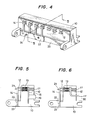
- Figs. 4 and 5 are views similar to Figs. 1 and 2 but show a first embodiment of the present invention. Like numerals are used to designate like or similar parts as in Figs. 1 - 3, thus needing no explanation hereof, except that the head carriage 10 has been molded of a suitable resin and a head assembly with permanent magnet 11, yoke 12, coils 13, printing boards 15, and connectors 16 has been integrally encapsulated when the head carriage 10 is molded.
- Permanent magnet 11, yoke 12, coils 13, printing boards 15, and connectors 16 and the like are first assembled. This assembly is then placed in a predetermined position within a mold for molding the head carriage 10. Resin is then conventionally poured or forced into the mold. The base of the typing hammers 14 is held fast by the screws 24 to the mounting surface 23 in front of the molded head carriage 10.
- Advantages derived from the present invention are that no location of the yoke 12 is required to facilitate assembling, and that the necessity of machining the head carriage is avoided, thereby making the head bank inexpensive.
- the position of the yoke 12 and typing hammers 14 are determined by positioning the yoke 12 by means of mold formation of the head carriage 10 but also the position of the mounting surface 23 on which the typing hammers 14 are rigidly mounted is determined by mold formation. This minimizes errors or tolerances which may otherwise result from mounting parts such as screws and the like.
- Figure 6 shows a second embodiment of the invention. Like elements have the same numerals as in Figures 4 and 5. As indicated above the printing board extends adjacent the magnet and weakens the magnetic force. Further, mounting the board and its connectors requires additional assembly. In Figure 6 the functions of the printing board are carried out by an external control circuit (not shown) and cable 30 encapsulated in head carriage 10 to connect coils 13 directly to that external circuit. Thus, assembly is simplified.
Landscapes
- Accessory Devices And Overall Control Thereof (AREA)
- Impact Printers (AREA)
Applications Claiming Priority (4)
| Application Number | Priority Date | Filing Date | Title |
|---|---|---|---|
| JP6284184A JPS60206667A (ja) | 1984-03-30 | 1984-03-30 | プリンタヘツドバンク |
| JP62841/84 | 1984-03-30 | ||
| JP134408/84 | 1984-06-29 | ||
| JP13440884A JPS6112353A (ja) | 1984-06-29 | 1984-06-29 | プリンタヘツドバンク |
Publications (2)
| Publication Number | Publication Date |
|---|---|
| EP0157624A2 true EP0157624A2 (fr) | 1985-10-09 |
| EP0157624A3 EP0157624A3 (fr) | 1987-07-29 |
Family
ID=26403896
Family Applications (1)
| Application Number | Title | Priority Date | Filing Date |
|---|---|---|---|
| EP85302264A Withdrawn EP0157624A3 (fr) | 1984-03-30 | 1985-04-01 | Banc de têtes d'impression et méthode de fabrication de celui-ci |
Country Status (2)
| Country | Link |
|---|---|
| US (1) | US4777875A (fr) |
| EP (1) | EP0157624A3 (fr) |
Cited By (3)
| Publication number | Priority date | Publication date | Assignee | Title |
|---|---|---|---|---|
| US4744686A (en) * | 1985-11-26 | 1988-05-17 | Hirotada Wakabayashi | Device for carrying printing head |
| GB2244955A (en) * | 1987-07-01 | 1991-12-18 | Printronix Inc | Magnetic arrangements in hammerbanks for dot-matrix printers. |
| EP0732213A3 (fr) * | 1995-03-15 | 1997-12-17 | Printronix, Inc. | Imprimante améliorée |
Families Citing this family (2)
| Publication number | Priority date | Publication date | Assignee | Title |
|---|---|---|---|---|
| US5237918A (en) * | 1987-05-09 | 1993-08-24 | Hitachi Koki Co., Ltd. | Printing head in a dot-line printer |
| US5335999A (en) * | 1992-12-08 | 1994-08-09 | Printronix, Inc. | Printer hammerspring |
Family Cites Families (9)
| Publication number | Priority date | Publication date | Assignee | Title |
|---|---|---|---|---|
| US4033255A (en) * | 1975-11-13 | 1977-07-05 | Printronix, Inc. | Print hammer actuator for dot matrix printers |
| DE2807337A1 (de) * | 1977-02-22 | 1978-08-31 | Information Magnetics Corp | Matrixdruckerkopf |
| US4258623A (en) * | 1979-01-30 | 1981-03-31 | Printronix, Inc. | Print hammer mechanism having dual electromagnetic coils and pole pieces |
| US4300845A (en) * | 1979-05-14 | 1981-11-17 | Qwint Systems, Inc. | Dot matrix print head |
| DE2939885C2 (de) * | 1979-10-02 | 1983-10-20 | Philips Patentverwaltung Gmbh, 2000 Hamburg | Nadeldruckkopf |
| JPS56146789A (en) * | 1980-04-18 | 1981-11-14 | Toshiba Corp | Typewriter |
| FR2482359A1 (fr) * | 1980-05-06 | 1981-11-13 | Staubli Sa Ets | Bloc de commande a electro-aimants, notamment pour l'actionnement des ratieres pour machines a tisser |
| IT1128976B (it) * | 1980-08-21 | 1986-06-04 | Olivetti & Co Spa | Testina di stampa a fili balistica |
| JPS5865672A (ja) * | 1981-10-16 | 1983-04-19 | Fujitsu Ltd | 印字ヘツド |
-
1985
- 1985-04-01 EP EP85302264A patent/EP0157624A3/fr not_active Withdrawn
-
1987
- 1987-01-15 US US07/006,311 patent/US4777875A/en not_active Expired - Fee Related
Cited By (3)
| Publication number | Priority date | Publication date | Assignee | Title |
|---|---|---|---|---|
| US4744686A (en) * | 1985-11-26 | 1988-05-17 | Hirotada Wakabayashi | Device for carrying printing head |
| GB2244955A (en) * | 1987-07-01 | 1991-12-18 | Printronix Inc | Magnetic arrangements in hammerbanks for dot-matrix printers. |
| EP0732213A3 (fr) * | 1995-03-15 | 1997-12-17 | Printronix, Inc. | Imprimante améliorée |
Also Published As
| Publication number | Publication date |
|---|---|
| EP0157624A3 (fr) | 1987-07-29 |
| US4777875A (en) | 1988-10-18 |
Similar Documents
| Publication | Publication Date | Title |
|---|---|---|
| EP0596638A1 (fr) | Système d'interconnexion à tolérance réduite | |
| US6225716B1 (en) | Commutator assembly apparatus for hall sensor devices | |
| US5527187A (en) | Compliant electrical interconnect | |
| EP0157624A2 (fr) | Banc de têtes d'impression et méthode de fabrication de celui-ci | |
| JPH05505878A (ja) | 再平衡コイルの応力分離を有した加速度計 | |
| US5313124A (en) | Return plate for a voice coil motor in a disk drive | |
| US12261503B2 (en) | Electric motor comprising a housing with a stator overmolding and connection assemblies | |
| EP0031432B1 (fr) | Assemblage de tête magnétique et de monture | |
| JPH03164704A (ja) | プラグインコネクタのフロート構造 | |
| CN223157455U (zh) | 伺服驱动装置和伺服系统 | |
| JPS6112353A (ja) | プリンタヘツドバンク | |
| US4709175A (en) | Linear pulse motor | |
| JPS5916227A (ja) | キ−ボ−ド装置 | |
| CN223040357U (zh) | 伺服驱动装置和伺服系统 | |
| JP2557935B2 (ja) | プリント配線板収納用筐体 | |
| JPH0424786Y2 (fr) | ||
| JPH0526798Y2 (fr) | ||
| JPH029663A (ja) | ムービングコイル型印字ヘッドのハンマ取付け装置 | |
| JP2739114B2 (ja) | 電子装置におけるバックボードの固定構造 | |
| JPS6327394Y2 (fr) | ||
| EP0063392B1 (fr) | Tête de lecture et/ou de gravure | |
| JPS6340857Y2 (fr) | ||
| JPS5838625Y2 (ja) | 高周波用印刷配線板 | |
| JPH041755Y2 (fr) | ||
| JPH0129834Y2 (fr) |
Legal Events
| Date | Code | Title | Description |
|---|---|---|---|
| PUAI | Public reference made under article 153(3) epc to a published international application that has entered the european phase |
Free format text: ORIGINAL CODE: 0009012 |
|
| AK | Designated contracting states |
Designated state(s): DE FR GB |
|
| PUAL | Search report despatched |
Free format text: ORIGINAL CODE: 0009013 |
|
| AK | Designated contracting states |
Kind code of ref document: A3 Designated state(s): DE FR GB |
|
| 17P | Request for examination filed |
Effective date: 19871223 |
|
| 17Q | First examination report despatched |
Effective date: 19890407 |
|
| RAP1 | Party data changed (applicant data changed or rights of an application transferred) |
Owner name: NEC HOME ELECTRONICS, LTD. |
|
| STAA | Information on the status of an ep patent application or granted ep patent |
Free format text: STATUS: THE APPLICATION IS DEEMED TO BE WITHDRAWN |
|
| 18D | Application deemed to be withdrawn |
Effective date: 19901003 |
|
| RIN1 | Information on inventor provided before grant (corrected) |
Inventor name: ENDO, KUNIOC/O NEC HOME ELECTRONICS LTD. Inventor name: FUJIWARA, SHINSUKEC/O NEC HOME ELECTRONICS LTD. |