EP0158008A2 - Arrangement de tuyau d'admission d'air pour un moteur polycylindrique à combustion interne - Google Patents
Arrangement de tuyau d'admission d'air pour un moteur polycylindrique à combustion interne Download PDFInfo
- Publication number
- EP0158008A2 EP0158008A2 EP85100552A EP85100552A EP0158008A2 EP 0158008 A2 EP0158008 A2 EP 0158008A2 EP 85100552 A EP85100552 A EP 85100552A EP 85100552 A EP85100552 A EP 85100552A EP 0158008 A2 EP0158008 A2 EP 0158008A2
- Authority
- EP
- European Patent Office
- Prior art keywords
- intake system
- air intake
- resonance
- cylinders
- suction pipes
- Prior art date
- Legal status (The legal status is an assumption and is not a legal conclusion. Google has not performed a legal analysis and makes no representation as to the accuracy of the status listed.)
- Granted
Links
Images


Classifications
-
- F—MECHANICAL ENGINEERING; LIGHTING; HEATING; WEAPONS; BLASTING
- F02—COMBUSTION ENGINES; HOT-GAS OR COMBUSTION-PRODUCT ENGINE PLANTS
- F02B—INTERNAL-COMBUSTION PISTON ENGINES; COMBUSTION ENGINES IN GENERAL
- F02B27/00—Use of kinetic or wave energy of charge in induction systems, or of combustion residues in exhaust systems, for improving quantity of charge or for increasing removal of combustion residues
- F02B27/02—Use of kinetic or wave energy of charge in induction systems, or of combustion residues in exhaust systems, for improving quantity of charge or for increasing removal of combustion residues the systems having variable, i.e. adjustable, cross-sectional areas, chambers of variable volume, or like variable means
- F02B27/0226—Use of kinetic or wave energy of charge in induction systems, or of combustion residues in exhaust systems, for improving quantity of charge or for increasing removal of combustion residues the systems having variable, i.e. adjustable, cross-sectional areas, chambers of variable volume, or like variable means characterised by the means generating the charging effect
- F02B27/0247—Plenum chambers; Resonance chambers or resonance pipes
- F02B27/0252—Multiple plenum chambers or plenum chambers having inner separation walls, e.g. comprising valves for the same group of cylinders
-
- F—MECHANICAL ENGINEERING; LIGHTING; HEATING; WEAPONS; BLASTING
- F02—COMBUSTION ENGINES; HOT-GAS OR COMBUSTION-PRODUCT ENGINE PLANTS
- F02B—INTERNAL-COMBUSTION PISTON ENGINES; COMBUSTION ENGINES IN GENERAL
- F02B27/00—Use of kinetic or wave energy of charge in induction systems, or of combustion residues in exhaust systems, for improving quantity of charge or for increasing removal of combustion residues
- F02B27/005—Oscillating pipes with charging achieved by arrangement, dimensions or shapes of intakes pipes or chambers; Ram air pipes
- F02B27/006—Oscillating pipes with charging achieved by arrangement, dimensions or shapes of intakes pipes or chambers; Ram air pipes of intake runners
-
- F—MECHANICAL ENGINEERING; LIGHTING; HEATING; WEAPONS; BLASTING
- F02—COMBUSTION ENGINES; HOT-GAS OR COMBUSTION-PRODUCT ENGINE PLANTS
- F02B—INTERNAL-COMBUSTION PISTON ENGINES; COMBUSTION ENGINES IN GENERAL
- F02B27/00—Use of kinetic or wave energy of charge in induction systems, or of combustion residues in exhaust systems, for improving quantity of charge or for increasing removal of combustion residues
- F02B27/008—Resonance charging
-
- F—MECHANICAL ENGINEERING; LIGHTING; HEATING; WEAPONS; BLASTING
- F02—COMBUSTION ENGINES; HOT-GAS OR COMBUSTION-PRODUCT ENGINE PLANTS
- F02B—INTERNAL-COMBUSTION PISTON ENGINES; COMBUSTION ENGINES IN GENERAL
- F02B75/00—Other engines
- F02B75/02—Engines characterised by their cycles, e.g. six-stroke
- F02B2075/022—Engines characterised by their cycles, e.g. six-stroke having less than six strokes per cycle
- F02B2075/027—Engines characterised by their cycles, e.g. six-stroke having less than six strokes per cycle four
-
- F—MECHANICAL ENGINEERING; LIGHTING; HEATING; WEAPONS; BLASTING
- F02—COMBUSTION ENGINES; HOT-GAS OR COMBUSTION-PRODUCT ENGINE PLANTS
- F02B—INTERNAL-COMBUSTION PISTON ENGINES; COMBUSTION ENGINES IN GENERAL
- F02B75/00—Other engines
- F02B75/16—Engines characterised by number of cylinders, e.g. single-cylinder engines
- F02B75/18—Multi-cylinder engines
- F02B2075/1804—Number of cylinders
- F02B2075/1824—Number of cylinders six
-
- F—MECHANICAL ENGINEERING; LIGHTING; HEATING; WEAPONS; BLASTING
- F02—COMBUSTION ENGINES; HOT-GAS OR COMBUSTION-PRODUCT ENGINE PLANTS
- F02B—INTERNAL-COMBUSTION PISTON ENGINES; COMBUSTION ENGINES IN GENERAL
- F02B75/00—Other engines
- F02B75/16—Engines characterised by number of cylinders, e.g. single-cylinder engines
- F02B75/18—Multi-cylinder engines
- F02B75/22—Multi-cylinder engines with cylinders in V, fan, or star arrangement
-
- F—MECHANICAL ENGINEERING; LIGHTING; HEATING; WEAPONS; BLASTING
- F02—COMBUSTION ENGINES; HOT-GAS OR COMBUSTION-PRODUCT ENGINE PLANTS
- F02B—INTERNAL-COMBUSTION PISTON ENGINES; COMBUSTION ENGINES IN GENERAL
- F02B75/00—Other engines
- F02B75/16—Engines characterised by number of cylinders, e.g. single-cylinder engines
- F02B75/18—Multi-cylinder engines
- F02B75/24—Multi-cylinder engines with cylinders arranged oppositely relative to main shaft and of "flat" type
- F02B75/243—Multi-cylinder engines with cylinders arranged oppositely relative to main shaft and of "flat" type with only one crankshaft of the "boxer" type, e.g. all connecting rods attached to separate crankshaft bearings
-
- F—MECHANICAL ENGINEERING; LIGHTING; HEATING; WEAPONS; BLASTING
- F02—COMBUSTION ENGINES; HOT-GAS OR COMBUSTION-PRODUCT ENGINE PLANTS
- F02F—CYLINDERS, PISTONS OR CASINGS, FOR COMBUSTION ENGINES; ARRANGEMENTS OF SEALINGS IN COMBUSTION ENGINES
- F02F2200/00—Manufacturing
- F02F2200/06—Casting
-
- Y—GENERAL TAGGING OF NEW TECHNOLOGICAL DEVELOPMENTS; GENERAL TAGGING OF CROSS-SECTIONAL TECHNOLOGIES SPANNING OVER SEVERAL SECTIONS OF THE IPC; TECHNICAL SUBJECTS COVERED BY FORMER USPC CROSS-REFERENCE ART COLLECTIONS [XRACs] AND DIGESTS
- Y02—TECHNOLOGIES OR APPLICATIONS FOR MITIGATION OR ADAPTATION AGAINST CLIMATE CHANGE
- Y02T—CLIMATE CHANGE MITIGATION TECHNOLOGIES RELATED TO TRANSPORTATION
- Y02T10/00—Road transport of goods or passengers
- Y02T10/10—Internal combustion engine [ICE] based vehicles
- Y02T10/12—Improving ICE efficiencies
Definitions
- the invention relates to an air intake system of a multi-cylinder internal combustion engine according to the preamble of claim 1.
- the object of the invention is to achieve a cost reduction and an increase in performance of the internal combustion engine by means of a special design and dimensioning of such an air intake system.
- the air intake system is designed to charge vibrations by dimensioning the total volume of the two resonance containers to be approximately the same size as the total stroke volume of all cylinders. Since the volume of the resonance container assigned to each cylinder group is approximately the same size as the stroke volume of this cylinder group, similar resonance conditions can be met between the connecting pipe of the distributor piece and the resonance containers, as between the cylinders and the suction pipes leading them from the resonance containers. That way you come for one 8-cylinder internal combustion engine with a single I-shaped distributor and thus achieves considerable cost savings. In addition, a considerable increase in power and torque can be achieved over a wide speed range of the internal combustion engine, which increases up to 10% in places.
- the suction pipes are connected to the resonance containers either on the same walls as the connecting pipe or in alignment with this on the opposite walls.
- the intake manifolds are curved and of different lengths, the curvature and length being coordinated in such a way that there is approximately the same pressure loss when flowing through for all intake manifolds.
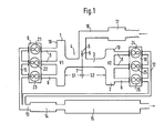
- An I-shaped distributor piece 4 is formed from a resonance container 1 with the volume V1, a resonance container 2 with the volume V2 and a connecting pipe 3.
- a suction nozzle 5, which contains a throttle valve 6, is connected vertically to the connecting pipe 3.
- One cylinder group 9 comprises cylinders Z1, Z2, Z3, the other cylinder group 10 includes cylinders Z4, Z5, Z6.
- the exhaust gases of the two cylinder groups 9, 10 are fed via exhaust manifolds 11, 12 to an exhaust pipe 13 and, after flowing through a pre-silencer 14 and a main silencer 15, are released into the open.
- the suction nozzle 5 is connected via a suction line 16 to an air filter 17 through which the air is sucked in from the atmosphere.
- the cylinders Z1, Z6, Z2, Z4, Z5, Z3 suck in one after the other according to their firing order from the resonance containers, between which a standing wave with zero passage is formed in the middle 7 of the suction nozzle. Since the suction pipes 8 of the cylinders are connected to the resonance containers 1, 2 on the sides 18, 19 opposite the connecting pipe 3, there is an approximately diagonal flow through the distributor piece during the suction, which flow continues in the respective suction pipes.
- the distributor piece 20 consists of the resonance containers 21, 22 with the volumes V21, V22 and the connecting pipe 23.
- the distributor piece 20 is an 8 between the two V-shaped cylinder groups 24, 25 -Cylinder internal combustion engine arranged, the cylinder group 24 comprises the cylinders Z1, Z2, Z3, Z4, the cylinder group 25 comprises the cylinders Z5, Z6, Z7, Z8.
- Suction pipes R1 to R8 lead to the cylinders, all of them Liche are connected to the same sides 26 and 27 of the resonance tank 21, 22 as the connecting pipe 23.
- the intake manifolds of one cylinder group 24 end in the common flange plane 28 of one cylinder head, the intake manifolds of the other cylinder group 25 in the flange plane 29 of the other cylinder head.
- the two inner cylinders 22, Z3 of the cylinder group 24 are connected to the resonance container 22 adjacent to the other cylinder group 25 by weakly bent suction pipes R2, R3.
- Suction pipes R6, R7 which emanate from the resonance container 24 adjacent to the cylinder group 24, lead to the inner cylinders Z6, Z7 of the cylinder group 25.
- the outer cylinders Z1 and Z4 as well as Z5 and Z8 are each connected to their adjacent resonance tank 24 and 25 by suction pipes R1 and R4 as well as R5 and R8.
- These suction pipes R1, R4, R5, R8 are shorter than the inner suction pipes and have a greater curvature that goes up to a 180 ° deflection.
- a suction branch 31 branches off vertically, via which the air is drawn in from an air filter (not shown).
- the total length 1 of the flow path from the inlet valve of one cylinder group to the subsequently opening inlet valve of the opposite cylinder group is decisive for the resonance tuning. If the sum of the flow cross sections of the intake pipes leading to a cylinder group is made the same size as the flow cross section of the connecting pipe, the oscillating charge can be optimally
Landscapes
- Engineering & Computer Science (AREA)
- Chemical & Material Sciences (AREA)
- Combustion & Propulsion (AREA)
- Mechanical Engineering (AREA)
- General Engineering & Computer Science (AREA)
- Characterised By The Charging Evacuation (AREA)
Applications Claiming Priority (2)
| Application Number | Priority Date | Filing Date | Title |
|---|---|---|---|
| DE3408899A DE3408899C2 (de) | 1983-03-16 | 1984-03-10 | Luftansauganlage einer Mehrzylinder-Brennkraftmaschine |
| DE3408899 | 1984-03-10 |
Publications (3)
| Publication Number | Publication Date |
|---|---|
| EP0158008A2 true EP0158008A2 (fr) | 1985-10-16 |
| EP0158008A3 EP0158008A3 (en) | 1986-02-05 |
| EP0158008B1 EP0158008B1 (fr) | 1988-03-16 |
Family
ID=6230164
Family Applications (1)
| Application Number | Title | Priority Date | Filing Date |
|---|---|---|---|
| EP85100552A Expired EP0158008B1 (fr) | 1984-03-10 | 1985-01-19 | Arrangement de tuyau d'admission d'air pour un moteur polycylindrique à combustion interne |
Country Status (4)
| Country | Link |
|---|---|
| US (1) | US4641610A (fr) |
| EP (1) | EP0158008B1 (fr) |
| JP (1) | JPH0692735B2 (fr) |
| DE (1) | DE3561900D1 (fr) |
Cited By (6)
| Publication number | Priority date | Publication date | Assignee | Title |
|---|---|---|---|---|
| EP0200930A1 (fr) * | 1985-05-09 | 1986-11-12 | Dr.Ing.h.c. F. Porsche Aktiengesellschaft | Système d'admission d'air pour moteur à combustion interne à pistons alternatifs |
| EP0278071A1 (fr) * | 1987-01-31 | 1988-08-17 | Dr.Ing.h.c. F. Porsche Aktiengesellschaft | Arrangement de collecteur d'admission pour un moteur à piston alternatif |
| GB2229768A (en) * | 1989-04-01 | 1990-10-03 | Keith Gordon Hall | I.c. engine air intake system |
| EP0402091A1 (fr) * | 1989-06-06 | 1990-12-12 | Mazda Motor Corporation | Moteur à quatre temps et à douze cylindres |
| EP0628707A1 (fr) * | 1993-05-07 | 1994-12-14 | Dr.Ing.h.c. F. Porsche Aktiengesellschaft | Système d'admission d'air d'un moteur à combustion interne |
| GB2286015A (en) * | 1994-01-29 | 1995-08-02 | Porsche Ag | Air intake unit of an i.c.engine |
Families Citing this family (20)
| Publication number | Priority date | Publication date | Assignee | Title |
|---|---|---|---|---|
| US4727829A (en) * | 1985-04-23 | 1988-03-01 | Yamaha Hatsudoki Kabushiki Kaisha | Intake system for internal combustion engine |
| US4957071A (en) * | 1988-07-26 | 1990-09-18 | Nissan Motor Co., Ltd. | Intake system for V-type internal combustion engine |
| JP2759461B2 (ja) * | 1988-10-12 | 1998-05-28 | ヤマハ発動機株式会社 | エンジンの吸気装置 |
| JP2767441B2 (ja) * | 1988-11-25 | 1998-06-18 | ヤマハ発動機株式会社 | V型多気筒エンジンの吸気装置 |
| JPH06105042B2 (ja) * | 1989-06-30 | 1994-12-21 | マツダ株式会社 | エンジンの吸気装置 |
| JPH03286129A (ja) * | 1990-03-30 | 1991-12-17 | Mazda Motor Corp | 多気筒エンジンの吸気装置 |
| JP2858706B2 (ja) * | 1990-03-31 | 1999-02-17 | マツダ株式会社 | V型エンジンの吸気装置 |
| US5010854A (en) * | 1990-07-12 | 1991-04-30 | Nissan Motor Co., Ltd. | Intake apparatus for V-type 8-cyl internal combustion engine |
| US5168838A (en) * | 1990-10-29 | 1992-12-08 | Mazda Motor Corporation | Engine induction system |
| US5136988A (en) * | 1991-08-19 | 1992-08-11 | Caterpillar Inc. | Air intake arrangement |
| JPH07197865A (ja) * | 1993-12-29 | 1995-08-01 | Yamaha Motor Co Ltd | V型多気筒エンジンの吸気装置 |
| DE4417472A1 (de) * | 1994-05-19 | 1995-11-30 | Porsche Ag | Luftangsauganalge einer mehrzylindrigen Brennkraftmaschine |
| JP3210825B2 (ja) * | 1995-01-14 | 2001-09-25 | ヤマハ発動機株式会社 | V型多気筒エンジンの吸気装置 |
| US5551386A (en) * | 1995-05-31 | 1996-09-03 | Gambardella; Bruce C. | Intake system for V-type engine |
| US5711261A (en) * | 1995-05-31 | 1998-01-27 | Gambardella; C. Bruce | Intake system for V-type engine |
| US5911205A (en) * | 1995-05-31 | 1999-06-15 | Gambardella; C. Bruce | Intake system for V-Type engine |
| DE102007014447B4 (de) * | 2007-03-27 | 2019-12-19 | Dr. Ing. H.C. F. Porsche Aktiengesellschaft | Aufgeladener Ottomotor mit variabler Sauganlage |
| DE102007034518A1 (de) * | 2007-07-24 | 2009-01-29 | Dr. Ing. H.C. F. Porsche Aktiengesellschaft | Luftfilter für eine Luftsauganlage einer mehrzylindrischen Brennkraftmaschine |
| US8807113B2 (en) * | 2009-05-04 | 2014-08-19 | Ford Global Technologies, Llc | Device and method for integrating an air cleaner into a radiator fan shroud |
| KR101470167B1 (ko) * | 2013-06-13 | 2014-12-05 | 현대자동차주식회사 | 엔진의 흡기계 |
Family Cites Families (13)
| Publication number | Priority date | Publication date | Assignee | Title |
|---|---|---|---|---|
| US3303832A (en) * | 1967-02-14 | High output engines | ||
| US1761958A (en) * | 1927-10-08 | 1930-06-03 | David E Anderson | Dual intake manifold |
| US2916027A (en) * | 1956-12-28 | 1959-12-08 | Gen Motors Corp | Charge forming means |
| US2947294A (en) * | 1957-06-10 | 1960-08-02 | Gen Motors Corp | Induction system |
| US2845912A (en) * | 1957-09-06 | 1958-08-05 | Gen Motors Corp | Induction system |
| US2947293A (en) * | 1958-12-17 | 1960-08-02 | Arkus-Duntov Zora | Manifold |
| US3026861A (en) * | 1960-08-18 | 1962-03-27 | Chrysler Corp | Exhaust gas heating system for intake manifold hot spot and control therefor |
| DE1231060B (de) * | 1963-02-21 | 1966-12-22 | Daimler Benz Ag | Saugrohranlage fuer Einspritz-Brennkraftmaschinen in Reihenbauart |
| FR1597395A (fr) * | 1968-08-01 | 1970-06-22 | ||
| HU175877B (en) * | 1978-07-07 | 1980-11-28 | Autoipari Kutato Intezet | Fresh gas duct system of resanator for internal combustion piston engines |
| HU182843B (en) * | 1978-12-21 | 1984-03-28 | Autoipari Kutato Fejlesztoe | Internal combustion piston engine with fresh gas conduit system boosting the supercharging of cylynders |
| DE2933331A1 (de) * | 1979-08-17 | 1981-02-26 | Bayerische Motoren Werke Ag | Saugrohranlage fuer 4- bis 6-zylinder- reihen-brennkraftmaschinen |
| IT1168721B (it) * | 1983-03-16 | 1987-05-20 | Porsche Ag | Macchina a combustione interna con sovralimentazione ad oscillazione |
-
1985
- 1985-01-19 DE DE8585100552T patent/DE3561900D1/de not_active Expired
- 1985-01-19 EP EP85100552A patent/EP0158008B1/fr not_active Expired
- 1985-03-07 US US06/709,432 patent/US4641610A/en not_active Expired - Fee Related
- 1985-03-08 JP JP60044997A patent/JPH0692735B2/ja not_active Expired - Lifetime
Cited By (10)
| Publication number | Priority date | Publication date | Assignee | Title |
|---|---|---|---|---|
| EP0200930A1 (fr) * | 1985-05-09 | 1986-11-12 | Dr.Ing.h.c. F. Porsche Aktiengesellschaft | Système d'admission d'air pour moteur à combustion interne à pistons alternatifs |
| EP0278071A1 (fr) * | 1987-01-31 | 1988-08-17 | Dr.Ing.h.c. F. Porsche Aktiengesellschaft | Arrangement de collecteur d'admission pour un moteur à piston alternatif |
| GB2229768A (en) * | 1989-04-01 | 1990-10-03 | Keith Gordon Hall | I.c. engine air intake system |
| EP0402091A1 (fr) * | 1989-06-06 | 1990-12-12 | Mazda Motor Corporation | Moteur à quatre temps et à douze cylindres |
| US5056472A (en) * | 1989-06-06 | 1991-10-15 | Mazda Motor Corporation | 4-cycle 12-cylinder engine |
| EP0628707A1 (fr) * | 1993-05-07 | 1994-12-14 | Dr.Ing.h.c. F. Porsche Aktiengesellschaft | Système d'admission d'air d'un moteur à combustion interne |
| US5406913A (en) * | 1993-05-07 | 1995-04-18 | Dr. Ing. H.C.F. Porsche Ag | Air intake system of an internal-combustion engine |
| GB2286015A (en) * | 1994-01-29 | 1995-08-02 | Porsche Ag | Air intake unit of an i.c.engine |
| US5495834A (en) * | 1994-01-29 | 1996-03-05 | Dr. Ing. H.C.F. Porsche Ag | Multi-cylinder internal-combustion engine air intake system |
| GB2286015B (en) * | 1994-01-29 | 1997-11-12 | Porsche Ag | Air-intake unit of a multiple-cylinder internal-combustion engine |
Also Published As
| Publication number | Publication date |
|---|---|
| DE3561900D1 (en) | 1988-04-21 |
| JPS60206929A (ja) | 1985-10-18 |
| EP0158008A3 (en) | 1986-02-05 |
| EP0158008B1 (fr) | 1988-03-16 |
| JPH0692735B2 (ja) | 1994-11-16 |
| US4641610A (en) | 1987-02-10 |
Similar Documents
| Publication | Publication Date | Title |
|---|---|---|
| EP0158008B1 (fr) | Arrangement de tuyau d'admission d'air pour un moteur polycylindrique à combustion interne | |
| EP0514645B1 (fr) | Système d'échappement pour moteur à combustion interne | |
| DE2702160C2 (de) | Ansaugsystem | |
| CH641245A5 (de) | Frischgasleitung an einem mehrzylinder-verbrennungsmotor. | |
| DE69514148T2 (de) | Abgassystem für Motor | |
| DE2525769B2 (de) | Freisaugende Achtzylinder-Dieselbrennkraftmaschine | |
| DE68916158T2 (de) | Einlassanordnung für Brennkraftmaschine mit V-förmig angeordneten Zylinderreihen. | |
| DE2625788B1 (de) | Abgasleitung fuer turboaufgeladene brennkraftmaschinen | |
| DE2621638A1 (de) | Frischgas-leitungssystem fuer sechszylindermotor mit turboaufladung | |
| DE2243269A1 (de) | Luftfuehrungssystem, insb. im ansaug fuer aufeinander folgende zylinder von hubkolben-brennkraftmaschinen | |
| DE2258686A1 (de) | Schalldaempfer und auspufftopf fuer schneemobile | |
| DE1933271C3 (de) | Saugrohranordnung für Brennkraftmaschinen | |
| DE4110597C2 (de) | Ansaugluft-Einlasssystem für eine Mehrzylinder-Brennkraftmaschine | |
| DE3408899C2 (de) | Luftansauganlage einer Mehrzylinder-Brennkraftmaschine | |
| DE2930697C2 (fr) | ||
| DE4030652A1 (de) | Verbrennungsmotor mit in v-form angeordneten zylinderbaenken | |
| DE4042415A1 (de) | Verbrennungsmotor mit in v-form angeordneten zylinderbaenken | |
| DE3208478C2 (de) | Auspuffkrümmer für einen Vierzylinder-Reihenmotor | |
| EP0278071A1 (fr) | Arrangement de collecteur d'admission pour un moteur à piston alternatif | |
| DE4110338A1 (de) | Ansaugrohraufbau fuer mehrzylindermotoren | |
| DE2750586C2 (de) | Saugrohranlage für Reihen-Brennkraftmaschinen | |
| DE2736466C3 (de) | Saugrohranlage fur Brennkraftmaschinen | |
| DE19940617A1 (de) | Ansaugkrümmer für Verbrennungsmotoren | |
| EP0373639A1 (fr) | Système de conduits de gaz d'échappement pour un moteur suralimenté | |
| EP0470390A1 (fr) | Système d'échappement pour moteur à combustion interne multicylindrique |
Legal Events
| Date | Code | Title | Description |
|---|---|---|---|
| PUAI | Public reference made under article 153(3) epc to a published international application that has entered the european phase |
Free format text: ORIGINAL CODE: 0009012 |
|
| AK | Designated contracting states |
Designated state(s): DE FR GB IT NL SE |
|
| PUAL | Search report despatched |
Free format text: ORIGINAL CODE: 0009013 |
|
| AK | Designated contracting states |
Designated state(s): DE FR GB IT NL SE |
|
| 17P | Request for examination filed |
Effective date: 19860226 |
|
| 17Q | First examination report despatched |
Effective date: 19861007 |
|
| D17Q | First examination report despatched (deleted) | ||
| ITF | It: translation for a ep patent filed | ||
| GRAA | (expected) grant |
Free format text: ORIGINAL CODE: 0009210 |
|
| AK | Designated contracting states |
Kind code of ref document: B1 Designated state(s): DE FR GB IT NL SE |
|
| REF | Corresponds to: |
Ref document number: 3561900 Country of ref document: DE Date of ref document: 19880421 |
|
| ET | Fr: translation filed | ||
| GBT | Gb: translation of ep patent filed (gb section 77(6)(a)/1977) | ||
| PLBE | No opposition filed within time limit |
Free format text: ORIGINAL CODE: 0009261 |
|
| STAA | Information on the status of an ep patent application or granted ep patent |
Free format text: STATUS: NO OPPOSITION FILED WITHIN TIME LIMIT |
|
| 26N | No opposition filed | ||
| ITTA | It: last paid annual fee | ||
| PGFP | Annual fee paid to national office [announced via postgrant information from national office to epo] |
Ref country code: SE Payment date: 19930115 Year of fee payment: 9 |
|
| PGFP | Annual fee paid to national office [announced via postgrant information from national office to epo] |
Ref country code: NL Payment date: 19930131 Year of fee payment: 9 |
|
| PG25 | Lapsed in a contracting state [announced via postgrant information from national office to epo] |
Ref country code: SE Effective date: 19940120 |
|
| PG25 | Lapsed in a contracting state [announced via postgrant information from national office to epo] |
Ref country code: NL Effective date: 19940801 |
|
| NLV4 | Nl: lapsed or anulled due to non-payment of the annual fee | ||
| PGFP | Annual fee paid to national office [announced via postgrant information from national office to epo] |
Ref country code: GB Payment date: 19950110 Year of fee payment: 11 |
|
| PGFP | Annual fee paid to national office [announced via postgrant information from national office to epo] |
Ref country code: DE Payment date: 19950116 Year of fee payment: 11 |
|
| PGFP | Annual fee paid to national office [announced via postgrant information from national office to epo] |
Ref country code: FR Payment date: 19950127 Year of fee payment: 11 |
|
| EUG | Se: european patent has lapsed |
Ref document number: 85100552.0 Effective date: 19940810 |
|
| PG25 | Lapsed in a contracting state [announced via postgrant information from national office to epo] |
Ref country code: GB Effective date: 19960119 |
|
| GBPC | Gb: european patent ceased through non-payment of renewal fee |
Effective date: 19960119 |
|
| PG25 | Lapsed in a contracting state [announced via postgrant information from national office to epo] |
Ref country code: FR Effective date: 19960930 |
|
| PG25 | Lapsed in a contracting state [announced via postgrant information from national office to epo] |
Ref country code: DE Effective date: 19961001 |
|
| REG | Reference to a national code |
Ref country code: FR Ref legal event code: ST |