EP0200930A1 - Système d'admission d'air pour moteur à combustion interne à pistons alternatifs - Google Patents
Système d'admission d'air pour moteur à combustion interne à pistons alternatifs Download PDFInfo
- Publication number
- EP0200930A1 EP0200930A1 EP86104644A EP86104644A EP0200930A1 EP 0200930 A1 EP0200930 A1 EP 0200930A1 EP 86104644 A EP86104644 A EP 86104644A EP 86104644 A EP86104644 A EP 86104644A EP 0200930 A1 EP0200930 A1 EP 0200930A1
- Authority
- EP
- European Patent Office
- Prior art keywords
- air
- intake system
- cylinders
- combustion engine
- air intake
- Prior art date
- Legal status (The legal status is an assumption and is not a legal conclusion. Google has not performed a legal analysis and makes no representation as to the accuracy of the status listed.)
- Withdrawn
Links
Images


Classifications
-
- F—MECHANICAL ENGINEERING; LIGHTING; HEATING; WEAPONS; BLASTING
- F02—COMBUSTION ENGINES; HOT-GAS OR COMBUSTION-PRODUCT ENGINE PLANTS
- F02B—INTERNAL-COMBUSTION PISTON ENGINES; COMBUSTION ENGINES IN GENERAL
- F02B27/00—Use of kinetic or wave energy of charge in induction systems, or of combustion residues in exhaust systems, for improving quantity of charge or for increasing removal of combustion residues
- F02B27/02—Use of kinetic or wave energy of charge in induction systems, or of combustion residues in exhaust systems, for improving quantity of charge or for increasing removal of combustion residues the systems having variable, i.e. adjustable, cross-sectional areas, chambers of variable volume, or like variable means
- F02B27/0226—Use of kinetic or wave energy of charge in induction systems, or of combustion residues in exhaust systems, for improving quantity of charge or for increasing removal of combustion residues the systems having variable, i.e. adjustable, cross-sectional areas, chambers of variable volume, or like variable means characterised by the means generating the charging effect
- F02B27/0247—Plenum chambers; Resonance chambers or resonance pipes
- F02B27/0252—Multiple plenum chambers or plenum chambers having inner separation walls, e.g. comprising valves for the same group of cylinders
-
- F—MECHANICAL ENGINEERING; LIGHTING; HEATING; WEAPONS; BLASTING
- F02—COMBUSTION ENGINES; HOT-GAS OR COMBUSTION-PRODUCT ENGINE PLANTS
- F02B—INTERNAL-COMBUSTION PISTON ENGINES; COMBUSTION ENGINES IN GENERAL
- F02B27/00—Use of kinetic or wave energy of charge in induction systems, or of combustion residues in exhaust systems, for improving quantity of charge or for increasing removal of combustion residues
- F02B27/02—Use of kinetic or wave energy of charge in induction systems, or of combustion residues in exhaust systems, for improving quantity of charge or for increasing removal of combustion residues the systems having variable, i.e. adjustable, cross-sectional areas, chambers of variable volume, or like variable means
- F02B27/0205—Use of kinetic or wave energy of charge in induction systems, or of combustion residues in exhaust systems, for improving quantity of charge or for increasing removal of combustion residues the systems having variable, i.e. adjustable, cross-sectional areas, chambers of variable volume, or like variable means characterised by the charging effect
- F02B27/0215—Oscillating pipe charging, i.e. variable intake pipe length charging
- F02B27/0221—Resonance charging combined with oscillating pipe charging
-
- F—MECHANICAL ENGINEERING; LIGHTING; HEATING; WEAPONS; BLASTING
- F02—COMBUSTION ENGINES; HOT-GAS OR COMBUSTION-PRODUCT ENGINE PLANTS
- F02B—INTERNAL-COMBUSTION PISTON ENGINES; COMBUSTION ENGINES IN GENERAL
- F02B27/00—Use of kinetic or wave energy of charge in induction systems, or of combustion residues in exhaust systems, for improving quantity of charge or for increasing removal of combustion residues
- F02B27/02—Use of kinetic or wave energy of charge in induction systems, or of combustion residues in exhaust systems, for improving quantity of charge or for increasing removal of combustion residues the systems having variable, i.e. adjustable, cross-sectional areas, chambers of variable volume, or like variable means
- F02B27/0226—Use of kinetic or wave energy of charge in induction systems, or of combustion residues in exhaust systems, for improving quantity of charge or for increasing removal of combustion residues the systems having variable, i.e. adjustable, cross-sectional areas, chambers of variable volume, or like variable means characterised by the means generating the charging effect
- F02B27/0247—Plenum chambers; Resonance chambers or resonance pipes
- F02B27/0263—Plenum chambers; Resonance chambers or resonance pipes the plenum chamber and at least one of the intake ducts having a common wall, and the intake ducts wrap partially around the plenum chamber, i.e. snail-type
-
- F—MECHANICAL ENGINEERING; LIGHTING; HEATING; WEAPONS; BLASTING
- F02—COMBUSTION ENGINES; HOT-GAS OR COMBUSTION-PRODUCT ENGINE PLANTS
- F02B—INTERNAL-COMBUSTION PISTON ENGINES; COMBUSTION ENGINES IN GENERAL
- F02B75/00—Other engines
- F02B75/16—Engines characterised by number of cylinders, e.g. single-cylinder engines
- F02B75/18—Multi-cylinder engines
- F02B2075/1804—Number of cylinders
- F02B2075/1832—Number of cylinders eight
-
- F—MECHANICAL ENGINEERING; LIGHTING; HEATING; WEAPONS; BLASTING
- F02—COMBUSTION ENGINES; HOT-GAS OR COMBUSTION-PRODUCT ENGINE PLANTS
- F02B—INTERNAL-COMBUSTION PISTON ENGINES; COMBUSTION ENGINES IN GENERAL
- F02B27/00—Use of kinetic or wave energy of charge in induction systems, or of combustion residues in exhaust systems, for improving quantity of charge or for increasing removal of combustion residues
- F02B27/02—Use of kinetic or wave energy of charge in induction systems, or of combustion residues in exhaust systems, for improving quantity of charge or for increasing removal of combustion residues the systems having variable, i.e. adjustable, cross-sectional areas, chambers of variable volume, or like variable means
- F02B27/0226—Use of kinetic or wave energy of charge in induction systems, or of combustion residues in exhaust systems, for improving quantity of charge or for increasing removal of combustion residues the systems having variable, i.e. adjustable, cross-sectional areas, chambers of variable volume, or like variable means characterised by the means generating the charging effect
- F02B27/0268—Valves
- F02B27/0273—Flap valves
-
- F—MECHANICAL ENGINEERING; LIGHTING; HEATING; WEAPONS; BLASTING
- F02—COMBUSTION ENGINES; HOT-GAS OR COMBUSTION-PRODUCT ENGINE PLANTS
- F02B—INTERNAL-COMBUSTION PISTON ENGINES; COMBUSTION ENGINES IN GENERAL
- F02B75/00—Other engines
- F02B75/16—Engines characterised by number of cylinders, e.g. single-cylinder engines
- F02B75/18—Multi-cylinder engines
- F02B75/22—Multi-cylinder engines with cylinders in V, fan, or star arrangement
-
- Y—GENERAL TAGGING OF NEW TECHNOLOGICAL DEVELOPMENTS; GENERAL TAGGING OF CROSS-SECTIONAL TECHNOLOGIES SPANNING OVER SEVERAL SECTIONS OF THE IPC; TECHNICAL SUBJECTS COVERED BY FORMER USPC CROSS-REFERENCE ART COLLECTIONS [XRACs] AND DIGESTS
- Y02—TECHNOLOGIES OR APPLICATIONS FOR MITIGATION OR ADAPTATION AGAINST CLIMATE CHANGE
- Y02T—CLIMATE CHANGE MITIGATION TECHNOLOGIES RELATED TO TRANSPORTATION
- Y02T10/00—Road transport of goods or passengers
- Y02T10/10—Internal combustion engine [ICE] based vehicles
- Y02T10/12—Improving ICE efficiencies
Definitions
- the invention relates to an air intake system according to the preamble of claim 1.
- the object of the invention is to further develop an air intake system so that it produces a torque increase without requiring a larger installation space.
- an opening which can be controlled by a rotary flap is provided in the partition and is released at speeds above approximately 4000 rpm.
- the individual suction pipes now suck in from the total volume of the air collection container and the torque remains up to a speed of approx. 5000 1 / min. at a constant height.
- the individual intake pipes are weakly bent, welded or cast together and form the top surface of the air collection container. Since they are thus integrated into the structure of the air collection container, this system requires a minimal installation space and can be produced at low manufacturing costs.
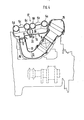
- the air intake system according to the invention is shown in the drawing and is explained in more detail below.
- a common air collection container 3 is on ordered, which is divided by a partition 4 into two equally large air spaces 5 and 6. From the air space 5, two individual suction pipes 5a and 5d lead to the cylinders 1a and 1d, two individual suction pipes 5b and 5c to the cylinders 2b and 2c of the other row of cylinders 2.
- the air space 6 is through individual suction pipes 6a and 6d with the cylinders 2a and 2d Individual suction pipes 6b and 6c connected to the cylinders 1b and 1c.
- the individual suction pipes all have an elongated length of about 300 mm.
- a rotary flap 8 is arranged, which is drawn in full in the open position and in dashed lines in the closed position. Even in the closed position, it has an air gap with the partition 4 in order to enable a slight exchange between the air spaces 5 and 6.
- intake pipes 9 and 10 with built-in throttle valves 11 and 12 lead via a pipe branch 13 to an air flow meter 14 and an air filter 15.
- a common throttle valve can also be used between the air flow meter 14 and the pipe branch 13 be used.
- the suction pipes 9 and 10 are designed to be quite long. Their length up to the pipe branch 13 is about twice as large as the stretched length of the individual suction pipes.
- the torque curve M d of an internal combustion engine as a function of its speed n achieved with such an air intake system is shown in FIG. 2.
- the curve e is obtained when the rotary flap 8 is open over the entire speed range or there is no partition, so the cylinders suck in from both air spaces. If you close the rotary flap in the entire speed range, so that the cylinders only suck in from one air space, either from 5 or from 6, it turns out a torque curve according to curve f with a torque increase of up to 10%. If you fit the rotary flap into the opening of the partition wall so that an air gap remains free, you get curve g, which shows a slightly lower torque increase. If you turn the flap at a speed n S about 3800 1 / min. goes into the open position, you avoid the sharp drop in torque after curve f. The torque remains constant in the speed range from 4000 to 5000 1 / min and is slightly above the torque, as can be seen in curve e.
- an air intake system according to the invention is shown in cross section and longitudinal section, which is mounted between the two rows of cylinders of a V8 internal combustion engine.
- the air flow from the air filter 15 via the air flow meter 14 to the intake manifolds 9, 10 and to the air collection container 3 is curved and adapted to the contour of the housing 16 of the internal combustion engine.
- the air collection container 3 extends in the longitudinal direction of the internal combustion engine. Its top surface 17 is formed by the individual suction pipes 5d, 5c, 6c, 6d, 5d, 5a cast together. On its underside 18, the air flows into the two air spaces 5, 6.
- the axis 19 of the rotary flap 8 protrudes from the underside 18 of the air collecting container 3 and is provided with an actuating lever 20 with which the rotary flap starts at a speed n s of approximately 3800 1 / min. is opened automatically and is kept open in the entire upper speed range in order to obtain the desired torque curve g.
Landscapes
- Engineering & Computer Science (AREA)
- Chemical & Material Sciences (AREA)
- Combustion & Propulsion (AREA)
- Mechanical Engineering (AREA)
- General Engineering & Computer Science (AREA)
- Characterised By The Charging Evacuation (AREA)
Applications Claiming Priority (2)
| Application Number | Priority Date | Filing Date | Title |
|---|---|---|---|
| DE3516674 | 1985-05-09 | ||
| DE19853516674 DE3516674A1 (de) | 1985-05-09 | 1985-05-09 | Luftansauganlage einer hubkolben-brennkraftmaschine |
Publications (1)
| Publication Number | Publication Date |
|---|---|
| EP0200930A1 true EP0200930A1 (fr) | 1986-11-12 |
Family
ID=6270238
Family Applications (1)
| Application Number | Title | Priority Date | Filing Date |
|---|---|---|---|
| EP86104644A Withdrawn EP0200930A1 (fr) | 1985-05-09 | 1986-04-04 | Système d'admission d'air pour moteur à combustion interne à pistons alternatifs |
Country Status (3)
| Country | Link |
|---|---|
| EP (1) | EP0200930A1 (fr) |
| JP (1) | JPS61258922A (fr) |
| DE (1) | DE3516674A1 (fr) |
Cited By (13)
| Publication number | Priority date | Publication date | Assignee | Title |
|---|---|---|---|---|
| EP0280121A3 (en) * | 1987-02-24 | 1989-09-27 | Bayerische Motoren Werke Aktiengesellschaft | Air plenum chamber |
| EP0387089A1 (fr) * | 1989-03-09 | 1990-09-12 | Honda Giken Kogyo Kabushiki Kaisha | Système d'admission pour moteur à combustion interne à plusieurs cylindres |
| EP0421116A1 (fr) * | 1989-09-30 | 1991-04-10 | Dr.Ing.h.c. F. Porsche Aktiengesellschaft | Système d'admission d'air pour moteur à combustion |
| GB2248652A (en) * | 1989-10-12 | 1992-04-15 | Fuji Heavy Ind Ltd | Twin bank i.c. engine intake arrangement |
| WO1993000505A3 (fr) * | 1991-06-24 | 1993-03-18 | Lotus Car | Collecteur d'admission pour un moteur a combustion interne a plusieurs cylindres |
| EP0400952B1 (fr) * | 1989-05-29 | 1995-07-12 | Honda Giken Kogyo Kabushiki Kaisha | Dispositif d'aspiration pour moteur à combustion interne multicylindrique |
| EP0790393A1 (fr) * | 1996-02-14 | 1997-08-20 | Bayerische Motoren Werke Aktiengesellschaft, Patentabteilung AJ-3 | Moteur à combustion interne avec un système d'admission avec un collecteur connecté à deux rangées de cylindres opposées, notamment pour un moteur V-8 |
| EP0987412A3 (fr) * | 1998-09-18 | 2000-11-08 | Dr.Ing. h.c.F. Porsche Aktiengesellschaft | Système d'admission |
| EP1338772A3 (fr) * | 2002-02-22 | 2005-05-25 | Mann + Hummel GmbH | Moteur à combustion interne |
| WO2007009624A1 (fr) * | 2005-07-22 | 2007-01-25 | Daimler Ag | Dispositif pourvu d'une unite pour actionner un moteur a combustion interne |
| CN100387822C (zh) * | 2004-10-06 | 2008-05-14 | 日产自动车株式会社 | 多缸发动机的进气装置 |
| EP1961935A2 (fr) * | 2007-02-23 | 2008-08-27 | Dr. Ing. h.c. F. Porsche Aktiengesellschaft | Dispositif d'aspiration à résonance commutable pour moteur à combustion interne |
| CN111042961A (zh) * | 2019-12-31 | 2020-04-21 | 潍柴动力股份有限公司 | 一种进气组件以及v型发动机 |
Families Citing this family (5)
| Publication number | Priority date | Publication date | Assignee | Title |
|---|---|---|---|---|
| DE4014291C2 (de) * | 1990-05-04 | 1994-03-10 | Daimler Benz Ag | Sauganlage für eine mehrzylindrige gemischverdichtende Brennkraftmaschine |
| DE4042415A1 (de) * | 1990-09-28 | 1992-11-19 | Daimler Benz Ag | Verbrennungsmotor mit in v-form angeordneten zylinderbaenken |
| DE4432349A1 (de) * | 1994-09-12 | 1996-03-14 | Bayerische Motoren Werke Ag | Schaltklappe für einen Brennkraftmaschinen-Luftsammler |
| DE10321323B3 (de) * | 2003-05-13 | 2004-12-16 | Dr.Ing.H.C. F. Porsche Ag | Sauganlage für eine Brennkraftmaschine mit mindestens zwei Zylinderbankreihen |
| JP4301074B2 (ja) | 2004-05-12 | 2009-07-22 | トヨタ自動車株式会社 | 多気筒エンジンの吸気装置 |
Citations (6)
| Publication number | Priority date | Publication date | Assignee | Title |
|---|---|---|---|---|
| US3303832A (en) * | 1967-02-14 | High output engines | ||
| GB2117043A (en) * | 1982-03-10 | 1983-10-05 | Ford Motor Co | Regulation of I.C. engine intake manifold resonance characteristics |
| EP0155685A2 (fr) * | 1984-03-22 | 1985-09-25 | Mazda Motor Corporation | Système d'admission pour moteur avec cylindres disposés en V |
| EP0158008A2 (fr) * | 1984-03-10 | 1985-10-16 | Dr.Ing.h.c. F. Porsche Aktiengesellschaft | Arrangement de tuyau d'admission d'air pour un moteur polycylindrique à combustion interne |
| EP0159803A2 (fr) * | 1984-04-16 | 1985-10-30 | General Motors Corporation | Système d'admission pour moteur à géométrie variable |
| EP0177794A1 (fr) * | 1984-10-10 | 1986-04-16 | Audi Ag | Dispositif d'admission pour moteurs polycylindriques |
-
1985
- 1985-05-09 DE DE19853516674 patent/DE3516674A1/de not_active Withdrawn
-
1986
- 1986-04-04 EP EP86104644A patent/EP0200930A1/fr not_active Withdrawn
- 1986-05-08 JP JP61103986A patent/JPS61258922A/ja active Pending
Patent Citations (6)
| Publication number | Priority date | Publication date | Assignee | Title |
|---|---|---|---|---|
| US3303832A (en) * | 1967-02-14 | High output engines | ||
| GB2117043A (en) * | 1982-03-10 | 1983-10-05 | Ford Motor Co | Regulation of I.C. engine intake manifold resonance characteristics |
| EP0158008A2 (fr) * | 1984-03-10 | 1985-10-16 | Dr.Ing.h.c. F. Porsche Aktiengesellschaft | Arrangement de tuyau d'admission d'air pour un moteur polycylindrique à combustion interne |
| EP0155685A2 (fr) * | 1984-03-22 | 1985-09-25 | Mazda Motor Corporation | Système d'admission pour moteur avec cylindres disposés en V |
| EP0159803A2 (fr) * | 1984-04-16 | 1985-10-30 | General Motors Corporation | Système d'admission pour moteur à géométrie variable |
| EP0177794A1 (fr) * | 1984-10-10 | 1986-04-16 | Audi Ag | Dispositif d'admission pour moteurs polycylindriques |
Cited By (15)
| Publication number | Priority date | Publication date | Assignee | Title |
|---|---|---|---|---|
| EP0280121A3 (en) * | 1987-02-24 | 1989-09-27 | Bayerische Motoren Werke Aktiengesellschaft | Air plenum chamber |
| EP0387089A1 (fr) * | 1989-03-09 | 1990-09-12 | Honda Giken Kogyo Kabushiki Kaisha | Système d'admission pour moteur à combustion interne à plusieurs cylindres |
| EP0400952B1 (fr) * | 1989-05-29 | 1995-07-12 | Honda Giken Kogyo Kabushiki Kaisha | Dispositif d'aspiration pour moteur à combustion interne multicylindrique |
| US5063884A (en) * | 1989-09-30 | 1991-11-12 | Dr. Ing. H.C.F. Porsche Ag | Air intake system of an internal-combustion engine |
| EP0421116A1 (fr) * | 1989-09-30 | 1991-04-10 | Dr.Ing.h.c. F. Porsche Aktiengesellschaft | Système d'admission d'air pour moteur à combustion |
| GB2248652A (en) * | 1989-10-12 | 1992-04-15 | Fuji Heavy Ind Ltd | Twin bank i.c. engine intake arrangement |
| WO1993000505A3 (fr) * | 1991-06-24 | 1993-03-18 | Lotus Car | Collecteur d'admission pour un moteur a combustion interne a plusieurs cylindres |
| EP0790393A1 (fr) * | 1996-02-14 | 1997-08-20 | Bayerische Motoren Werke Aktiengesellschaft, Patentabteilung AJ-3 | Moteur à combustion interne avec un système d'admission avec un collecteur connecté à deux rangées de cylindres opposées, notamment pour un moteur V-8 |
| EP0987412A3 (fr) * | 1998-09-18 | 2000-11-08 | Dr.Ing. h.c.F. Porsche Aktiengesellschaft | Système d'admission |
| US6250272B1 (en) | 1998-09-18 | 2001-06-26 | Dr. Ing. H.C.F. Porsche Ag | Internal combustion engine suction system utilizing resonance |
| EP1338772A3 (fr) * | 2002-02-22 | 2005-05-25 | Mann + Hummel GmbH | Moteur à combustion interne |
| CN100387822C (zh) * | 2004-10-06 | 2008-05-14 | 日产自动车株式会社 | 多缸发动机的进气装置 |
| WO2007009624A1 (fr) * | 2005-07-22 | 2007-01-25 | Daimler Ag | Dispositif pourvu d'une unite pour actionner un moteur a combustion interne |
| EP1961935A2 (fr) * | 2007-02-23 | 2008-08-27 | Dr. Ing. h.c. F. Porsche Aktiengesellschaft | Dispositif d'aspiration à résonance commutable pour moteur à combustion interne |
| CN111042961A (zh) * | 2019-12-31 | 2020-04-21 | 潍柴动力股份有限公司 | 一种进气组件以及v型发动机 |
Also Published As
| Publication number | Publication date |
|---|---|
| DE3516674A1 (de) | 1986-11-13 |
| JPS61258922A (ja) | 1986-11-17 |
Similar Documents
| Publication | Publication Date | Title |
|---|---|---|
| EP0200930A1 (fr) | Système d'admission d'air pour moteur à combustion interne à pistons alternatifs | |
| DE3502699C2 (fr) | ||
| EP0177794B1 (fr) | Dispositif d'admission pour moteurs polycylindriques | |
| DE2702160C2 (de) | Ansaugsystem | |
| DE3711096C2 (de) | Ansaugsystem für eine Mehrzylinder-Brennkraftmaschine | |
| EP0389834A1 (fr) | Arrangement des conduits d'admission pour un moteur à combustion à plusieurs cylindres | |
| DE3414710A1 (de) | Verbrennungsmotor mit v-foermiger zylinderanordnung | |
| DE3433011C2 (fr) | ||
| DE1476218C3 (de) | Ansauganordnung für Brennkraftmaschinen mit Aufladeeffekt | |
| DE68916158T2 (de) | Einlassanordnung für Brennkraftmaschine mit V-förmig angeordneten Zylinderreihen. | |
| DE4117466A1 (de) | Ansaugsystem fuer eine mehrzylinder-brennkraftmaschine | |
| DE19535626C2 (de) | Einlaßschalldämpfer in einem Vertikal-Motor | |
| EP0987412A2 (fr) | Système d'admission | |
| DE2625788B1 (de) | Abgasleitung fuer turboaufgeladene brennkraftmaschinen | |
| DE3631124C2 (de) | Ansaugsystem für eine Brennkraftmaschine | |
| DE3628230C2 (de) | Ansaugsystem für Verbrennungsmotoren | |
| DE4039992C2 (fr) | ||
| DE3728179C2 (fr) | ||
| DE4110597C2 (de) | Ansaugluft-Einlasssystem für eine Mehrzylinder-Brennkraftmaschine | |
| DE69611876T2 (de) | Brennkraftmaschine mit Einlasssystem mit veränderlicher Geometrie für ein Fahrzeug | |
| DE69817005T2 (de) | Zweitakt-motor | |
| DE3633929C2 (de) | Luftansauganlage für einen Boxer- oder V-Motor | |
| DE7803641U1 (de) | Viertaktbrennkraftmaschine | |
| DE3923924C2 (de) | Steuervorrichtung für das Saugrohrsystem einer Fahrzeugbrennkraftmaschine | |
| DE19509002C2 (de) | Thermostatanbaupositionsstruktur |
Legal Events
| Date | Code | Title | Description |
|---|---|---|---|
| PUAI | Public reference made under article 153(3) epc to a published international application that has entered the european phase |
Free format text: ORIGINAL CODE: 0009012 |
|
| AK | Designated contracting states |
Kind code of ref document: A1 Designated state(s): DE FR GB IT SE |
|
| 17P | Request for examination filed |
Effective date: 19870319 |
|
| 17Q | First examination report despatched |
Effective date: 19870818 |
|
| STAA | Information on the status of an ep patent application or granted ep patent |
Free format text: STATUS: THE APPLICATION HAS BEEN WITHDRAWN |
|
| 18W | Application withdrawn |
Withdrawal date: 19871111 |
|
| RIN1 | Information on inventor provided before grant (corrected) |
Inventor name: SCHMID, WOLFGANG |