EP0158069B2 - Dispositif de fermeture et de verrouillage pour une porte ou analogue - Google Patents
Dispositif de fermeture et de verrouillage pour une porte ou analogue Download PDFInfo
- Publication number
- EP0158069B2 EP0158069B2 EP85102005A EP85102005A EP0158069B2 EP 0158069 B2 EP0158069 B2 EP 0158069B2 EP 85102005 A EP85102005 A EP 85102005A EP 85102005 A EP85102005 A EP 85102005A EP 0158069 B2 EP0158069 B2 EP 0158069B2
- Authority
- EP
- European Patent Office
- Prior art keywords
- closing
- door
- bolt
- guide
- drive rod
- Prior art date
- Legal status (The legal status is an assumption and is not a legal conclusion. Google has not performed a legal analysis and makes no representation as to the accuracy of the status listed.)
- Expired - Lifetime
Links
- 239000002184 metal Substances 0.000 claims abstract description 11
- 230000003014 reinforcing effect Effects 0.000 claims description 3
- 239000002023 wood Substances 0.000 abstract description 2
- 238000004873 anchoring Methods 0.000 description 9
- 230000015572 biosynthetic process Effects 0.000 description 2
- 238000006073 displacement reaction Methods 0.000 description 2
- 230000000694 effects Effects 0.000 description 2
- 239000000463 material Substances 0.000 description 2
- 229910000831 Steel Inorganic materials 0.000 description 1
- 238000005452 bending Methods 0.000 description 1
- 230000005540 biological transmission Effects 0.000 description 1
- 238000005553 drilling Methods 0.000 description 1
- 238000004519 manufacturing process Methods 0.000 description 1
- 239000010959 steel Substances 0.000 description 1
- 230000007704 transition Effects 0.000 description 1
Images


Classifications
-
- E—FIXED CONSTRUCTIONS
- E05—LOCKS; KEYS; WINDOW OR DOOR FITTINGS; SAFES
- E05B—LOCKS; ACCESSORIES THEREFOR; HANDCUFFS
- E05B15/00—Other details of locks; Parts for engagement by bolts of fastening devices
- E05B15/02—Striking-plates; Keepers; Bolt staples; Escutcheons
- E05B15/0205—Striking-plates, keepers, staples
Definitions
- the invention relates to a locking and locking device for a door or a window with a plurality of immovable locking elements, each locking element being held by at least one screw, preferably arranged in the door plane, the immovable and immovable locking element being held by at least two additional fastening elements and the longitudinal axis of a first of these additional fastening elements extends transversely to that of the screw, the second of these additional fastening elements being a metal screw, the inner end of which engages in a nut thread in the interior of the first fastening element.
- the object of the invention is now to develop the locking and locking device of the type mentioned in such a way that there is an improved securing effect.
- each interacting with an immovable locking element movable locking members are attached to a drive rod and the drive rod to increase the resistance to evasion during an attempted break-in in the range of movement of the locking member in a metal guide piece with little play
- the guide piece is formed by the slotted outer end of a cylindrical guide bolt inserted into a receptacle of the associated door rail or door edge region, and in that the guide piece of the guide bolt is arranged in an open-ended groove covered by a faceplate, which is located in the narrow side of the door on the closing side
- the locking members consist of cylindrical bolts which protrude in the direction perpendicular to the bottom of the groove from the drive rod and protrude through corresponding elongated holes in the faceplate, and wherein the Schl wareetti are designed such that they engage behind a portion of the cylindrical bolt in their closed position.
- the door can be locked in several places with respect to the fixed frame, making it better able to withstand an attempt to break in.
- All locking members are moved in a manner known per se by means of a drive rod, and therefore the impact on the drive rod in the region of each locking member is particularly high in the event of an attempted break-in. Due to the guidance in the area of each locking member, the drive rod can practically perform no transverse movement due to the small clearance selected, so that the forces which occur are transmitted directly to the door via the guide bolts.
- the minimal play prevents the formation of a significant gap between the door and the fixed frame in contrast to the previous version with locking and locking devices with locking pins and multi-point locking, where on the one hand the locking pins tend to tilt and on the other hand a relatively large gap can be formed by pulling on the door , which can be used to attach a chisel or the like.
- a further development of the invention provides that the nut thread for the additional fastening element of the closing element is located on a bolt which is inserted into a receptacle, in particular a bore, of the fixed frame or the door or the window, the longitudinal axis of the bolt in the Door level or runs parallel to it.
- the use of a bolt is relatively simple and it ensures a good securing effect with little effort.
- the guide pin for the drive rod is also characterized by simple assembly with a circular cross section. Again, drilling a hole is sufficient.
- a further development of the invention provides that the longitudinal axis of the guide pin extends transversely, in particular perpendicularly, to the longitudinal axis of the drive rod and that it is located in the plane of the door. This allows considerable forces to be absorbed.
- a further embodiment of the invention is characterized by non-displaceable or immovable locking elements on the rotary axis side, designed as locking wedges of locking wedge pairs, the wedge surfaces of the locking wedges being roughened, in particular designed in a step-like manner.
- roughened closing wedge surfaces which are above all designed in a stepped manner, can absorb large forces. Wedge surfaces with serration provide considerable resistance to slipping.
- each locking wedge on the sash frame has a rear inner guide web which engages in a guide groove of a reinforcing element, in particular a retaining bolt.
- the latter is also easy to assemble and reinforces the anchoring of this locking wedge in the fixed frame or frame.
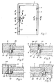
- the lock members attached to the lock side of the door and attached to a common, possibly split drive rod 7 can be moved up and down to remove them from an ineffective to move to a locked position and vice versa.
- Each locking member which is preferably designed as a locking pin, cooperates with an immovable locking element 10 which is mounted on the fixed frame 3, more precisely on the vertical stile 9 of the fixed frame, which is preferably designed as a locking plate.
- the latter is edge-open in at least one place in a known manner, so that the locking member 8 can emerge in the unlocked position when the door is opened.
- the immovable locking element 11 is designed as a locking plate (FIG. 4). It has in a known manner an engagement opening for a bolt 12 and the latch 4, which can be actuated by the pawl 5.
- a suitable transmission mechanism inside the lock 4 converts the rotary movement of the key into the displacement movements of the drive rod 7.
- the latch can also be operated from the outside using the key, because in the case of an outer door there is generally only a latch 5 on the inside.
- the door 1 can be locked on the lock side in relation to the fixed frame 3 at several locations distributed over the entire door height. If you continue the drive rod at its upper end via a corner drive, you can also lock it at the upper end of the door.
- the wing-side striker is designated 13 and the frame side 14. They are assembled and designed in such a way that when the door is closed, the striker 13 engages behind the striker 14 on the frame 2 in the manner shown in FIG.
- the abutting wedge surfaces 15 and 16 are roughened, grooved, toothed or shaped like a staircase. This prevents the wedge 13 from sliding on the wedge 14 when a force is applied transversely to the door plane.
- Both the locking plates 10 and the immovable locking elements which are designed as locking wedges 14, are screwed to their vertical frame frame 9 and 19 with the aid of at least one screw 17 and 18 arranged in the door plane.
- at least one additional fastening element 20 or 21, preferably also in the form of a screw is provided, the longitudinal axis of which extends transversely to the door plane.
- the exemplary embodiment does not provide a fastening screw extending in the door plane in the case of the non-displaceable closing element of the fixed frame 3, which is designed as a striking plate 11, but there is nevertheless anchoring in the longitudinal and transverse directions, so that this non-displaceable closing element in the same way as that just described described is securely anchored in the frame.
- an additional fastening element is used, which is advantageously designed as a machine or metal screw 23 with anchoring bolts 25.
- the inner end of the metal screw 23 engages in a thread 24 of the anchoring bolt 25, the longitudinal axis of which extends transversely, in particular perpendicularly, to that of the metal screw and consequently extends in or parallel to the door plane.
- the screw 23 and the anchoring bolt 25 thus form a two-part, angled anchoring element.
- a machine or metal screw 20 is also used in the embodiment according to FIG. 3. Its inner end also engages in a thread 26 of a bolt 27, both of which together form a two-part, additional fastening element.
- the bolt 27 extends parallel to the plane of the door 1 or to the longitudinal axis of the metal screw 17 and it is inserted flush into the outside of a blind hole 28 of the fixed frame 3 or of the vertical spar 9.
- a corresponding blind bore for the anchoring bolt 25 (FIG. 10) is designated 29.
- the door or leaf-side locking wedge 30 is mounted with screws 18 and fastening elements 21, which are preferably also screws, with the axes again running transversely, in particular perpendicularly to one another.
- this locking wedge carries on its inner contact surface a guide web 30 which engages in a guide groove 31 of a reinforcing element 32.
- the latter is preferably a retaining bolt which is comparable to the other bolts already mentioned and whose longitudinal axis runs horizontally in the door plane. This can further improve the anchoring of this striker 13.
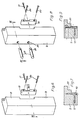
- the locking members 8 designed as pins or bolts are, as already explained, attached to a drive rod 7, in particular riveted.
- the latter is covered by a faceplate 33 and is slidably mounted in a groove 34 of the door spar or door edge area which is open at the edge.
- the drive rod 7 is guided in the area of the locking member 8 in a metal guide piece 35 with very little play. It is practically impossible to avoid the drive rod transversely to its longitudinal axis and to the door plane.
- the approximately U-shaped guide piece 35 is formed by the slotted end of a guide pin 36 inserted into a receptacle 37 of the door edge region. The game corresponds to that of a sliding seat and allows an unimpeded displacement of the drive rod through the guide slot.
- This device is preferably used for a wooden door and a frame made of wood.
- the strikers 10, the striking plate 11, the strikers 13 and 14 and the various bolts are then made of steel or a steel-like material. This creates a burglar-resistant fitting that meets the requirements of a relevant standard. On the other hand, it is relatively inexpensive to manufacture and assemble.
Landscapes
- Power-Operated Mechanisms For Wings (AREA)
- Joining Of Corner Units Of Frames Or Wings (AREA)
- Lock And Its Accessories (AREA)
Claims (5)
Priority Applications (1)
| Application Number | Priority Date | Filing Date | Title |
|---|---|---|---|
| AT85102005T ATE41040T1 (de) | 1984-04-07 | 1985-02-23 | Schliess- und verriegelungsvorrichtung fuer eine tuer od. dgl. |
Applications Claiming Priority (2)
| Application Number | Priority Date | Filing Date | Title |
|---|---|---|---|
| DE8413184U | 1984-04-07 | ||
| DE19848413184U DE8413184U1 (de) | 1984-04-07 | 1984-04-07 | Schliess- und verriegelungsvorrichtung fuer eine tuer od. dgl. |
Publications (3)
| Publication Number | Publication Date |
|---|---|
| EP0158069A1 EP0158069A1 (fr) | 1985-10-16 |
| EP0158069B1 EP0158069B1 (fr) | 1989-03-01 |
| EP0158069B2 true EP0158069B2 (fr) | 1993-08-25 |
Family
ID=6766394
Family Applications (1)
| Application Number | Title | Priority Date | Filing Date |
|---|---|---|---|
| EP85102005A Expired - Lifetime EP0158069B2 (fr) | 1984-04-07 | 1985-02-23 | Dispositif de fermeture et de verrouillage pour une porte ou analogue |
Country Status (3)
| Country | Link |
|---|---|
| EP (1) | EP0158069B2 (fr) |
| AT (1) | ATE41040T1 (fr) |
| DE (1) | DE8413184U1 (fr) |
Families Citing this family (2)
| Publication number | Priority date | Publication date | Assignee | Title |
|---|---|---|---|---|
| DE19853544B4 (de) * | 1998-11-20 | 2007-09-06 | Siegenia-Aubi Kg | Beschlagteil für Fenster oder Türen mit Andruckverstellvorrichtung |
| RU2225930C1 (ru) * | 2003-02-18 | 2004-03-20 | Общество с ограниченной ответственностью Научно-производственный центр "Экопром" | Дверная задвижка |
Family Cites Families (12)
| Publication number | Priority date | Publication date | Assignee | Title |
|---|---|---|---|---|
| DE348261C (de) | 1920-12-18 | 1922-02-03 | Franz Rapsch | Befestigung von Tuerbeschlaegen |
| DE1708235A1 (de) | 1967-06-02 | 1971-04-29 | Siegenia Frank Kg | Dreh-Kippbeschlag fuer Fenster,Tueren oder aehnliche Raumabschlussorgane |
| AT287535B (de) | 1968-03-13 | 1971-01-25 | Frank Gmbh Wilh | Beschlag fuer wahlweise um eine lotrechte achse schwenkbare oder um eine waagrechte achse kippbare fluegel von fenstern, tueren od.dgl |
| DE1995891U (de) | 1968-08-07 | 1968-10-31 | Jaeger Frank K G Fa | Treibstangenbeschlag, insbesondere fuer kipp-schwenkfluegel von fenstern, tueren od. dgl. |
| DE2020240C3 (de) * | 1970-04-25 | 1983-01-13 | Wilh. Frank Gmbh, 7022 Leinfelden-Echterdingen | Verschluss für einen Schwenk-Kippflügel eines Fensters, einer Tür o.dgl. |
| US3970340A (en) * | 1975-06-19 | 1976-07-20 | Lawrence Peska Associates, Inc. | Hinge pin locks |
| DE2553607A1 (de) | 1975-11-28 | 1977-06-08 | Moralt Kg August | Holztuerstock mit einem schliessblech |
| DE2613267A1 (de) | 1976-03-27 | 1977-09-29 | Fliether Fa Karl | Winkelschliessblech |
| US4105235A (en) * | 1977-06-20 | 1978-08-08 | Thiel Frank C | Lock keeper |
| DE2831896C2 (de) * | 1978-07-20 | 1985-02-14 | Gretsch-Unitas Gmbh Baubeschlagfabrik, 7257 Ditzingen | Zahnradantrieb in einem schließzylinderbetätigbaren Treibstangenschloß |
| AT368586B (de) | 1981-01-28 | 1982-10-25 | Grundmann Rohrbacher Schlosser | Widerlager zur aufnahme des freien endes von sperrorganen |
| CA1142202A (fr) * | 1982-02-10 | 1983-03-01 | William J. Hamilton | Fixation de gache |
-
1984
- 1984-04-07 DE DE19848413184U patent/DE8413184U1/de not_active Expired
-
1985
- 1985-02-23 AT AT85102005T patent/ATE41040T1/de not_active IP Right Cessation
- 1985-02-23 EP EP85102005A patent/EP0158069B2/fr not_active Expired - Lifetime
Also Published As
| Publication number | Publication date |
|---|---|
| ATE41040T1 (de) | 1989-03-15 |
| DE8413184U1 (de) | 1984-08-09 |
| EP0158069A1 (fr) | 1985-10-16 |
| EP0158069B1 (fr) | 1989-03-01 |
Similar Documents
| Publication | Publication Date | Title |
|---|---|---|
| DE68903888T2 (de) | Schliessvorrichtung fuer treib- oder riegelstangenbeschlag und aehnliches. | |
| EP0433623B1 (fr) | Dispositif de verrouillage d'une fenêtre, d'une porte ou similaires | |
| EP2113624B1 (fr) | Dispositif de fixation de porte ou de fenêtre | |
| EP0002248B2 (fr) | Dispositif de fermeture avec des tringles de commande pour le battant à usage secondaire d'une fenêtre ou d'une porte à deux battants sans jambage du milieu | |
| EP0761920B1 (fr) | Fenêtre/porte avec battant pivotant et/ou basculant | |
| EP0158069B1 (fr) | Dispositif de fermeture et de verrouillage pour une porte ou analogue | |
| DE9402161U1 (de) | Zusatzverriegelungsvorrichtung für ein Fenster, eine Tür o.dgl. mit einem wenigstens drehbarem Flügel | |
| EP1580374B1 (fr) | Fenêtre ou porte | |
| EP0733761B1 (fr) | Cadre de battant | |
| EP4573251A1 (fr) | Dispositif de décalage permettant le décalage forcé d'un battant, en particulier d'un battant coulissant, d'une fenêtre ou d'une porte | |
| DE19745553A1 (de) | Schließvorrichtung | |
| EP0930410B1 (fr) | Poignée de manoeuvre | |
| EP0500125B1 (fr) | Dispositif de blocage pour fenêtres ou portes | |
| DE19608173A1 (de) | Schloß, insbesondere Zusatzschloß | |
| EP0435115B1 (fr) | Arrêt de porte, fenêtre ou similaire | |
| EP0128372A2 (fr) | Dispositif de fermeture d'un battant d'une porte, fenêtre ou similaire à deux battants | |
| DE4236432A1 (en) | Drive rod fixture for door or window with or without lock - is arranged in peripheral groove of panel or pane and incorporates operating mechanism in housing for operation of at least one drive rod | |
| CH660051A5 (en) | Espagnolette fastening for the bottom-closing wing of two-wing windows or doors without a mullion | |
| EP0280950B1 (fr) | Strip de fermeture pour porte, fenêtre ou similaire | |
| EP1659241B1 (fr) | Ferrure pour dispositif anti-effraction de fenetre ou de porte a plusieurs vantaux | |
| DE19504419C2 (de) | Treibstangenbeschlag | |
| EP0730074A2 (fr) | Ferrure pour champ de porte d'un battant semi-fixe de portes à deux battants | |
| DE4203909A1 (de) | Kippriegelvorrichtung | |
| DE202007003750U1 (de) | Standflügel und Standflügelverschluss | |
| DE102024207026A1 (de) | Beschlaganordnung mit einem Zusatzriegel, insbesondere für zweiflüglige Fenster oder Türen ohne mittigen Setzpfosten |
Legal Events
| Date | Code | Title | Description |
|---|---|---|---|
| PUAI | Public reference made under article 153(3) epc to a published international application that has entered the european phase |
Free format text: ORIGINAL CODE: 0009012 |
|
| AK | Designated contracting states |
Designated state(s): AT BE CH FR LI NL |
|
| 17P | Request for examination filed |
Effective date: 19850830 |
|
| 17Q | First examination report despatched |
Effective date: 19860527 |
|
| GRAA | (expected) grant |
Free format text: ORIGINAL CODE: 0009210 |
|
| AK | Designated contracting states |
Kind code of ref document: B1 Designated state(s): AT BE CH FR LI NL |
|
| REF | Corresponds to: |
Ref document number: 41040 Country of ref document: AT Date of ref document: 19890315 Kind code of ref document: T |
|
| ET | Fr: translation filed | ||
| PLBI | Opposition filed |
Free format text: ORIGINAL CODE: 0009260 |
|
| 26 | Opposition filed |
Opponent name: SIEGENIA-FRANK KG Effective date: 19891010 |
|
| PLBI | Opposition filed |
Free format text: ORIGINAL CODE: 0009260 |
|
| 26 | Opposition filed |
Opponent name: ROTO FRANK AKTIENGESELLSCHAFT Effective date: 19891128 Opponent name: SIEGENIA-FRANK KG Effective date: 19891010 |
|
| NLR1 | Nl: opposition has been filed with the epo |
Opponent name: SIEGENIA-FRANK KG |
|
| NLR1 | Nl: opposition has been filed with the epo |
Opponent name: ROTO FRANK AG. |
|
| PUAH | Patent maintained in amended form |
Free format text: ORIGINAL CODE: 0009272 |
|
| STAA | Information on the status of an ep patent application or granted ep patent |
Free format text: STATUS: PATENT MAINTAINED AS AMENDED |
|
| 27A | Patent maintained in amended form |
Effective date: 19930825 |
|
| AK | Designated contracting states |
Kind code of ref document: B2 Designated state(s): AT BE CH FR LI NL |
|
| ET3 | Fr: translation filed ** decision concerning opposition | ||
| NLR2 | Nl: decision of opposition | ||
| NLR3 | Nl: receipt of modified translations in the netherlands language after an opposition procedure | ||
| PGFP | Annual fee paid to national office [announced via postgrant information from national office to epo] |
Ref country code: FR Payment date: 19990115 Year of fee payment: 15 |
|
| PGFP | Annual fee paid to national office [announced via postgrant information from national office to epo] |
Ref country code: NL Payment date: 19990119 Year of fee payment: 15 |
|
| PGFP | Annual fee paid to national office [announced via postgrant information from national office to epo] |
Ref country code: AT Payment date: 19990126 Year of fee payment: 15 |
|
| PGFP | Annual fee paid to national office [announced via postgrant information from national office to epo] |
Ref country code: CH Payment date: 19990201 Year of fee payment: 15 Ref country code: BE Payment date: 19990201 Year of fee payment: 15 |
|
| PG25 | Lapsed in a contracting state [announced via postgrant information from national office to epo] |
Ref country code: AT Free format text: LAPSE BECAUSE OF NON-PAYMENT OF DUE FEES Effective date: 20000223 |
|
| PG25 | Lapsed in a contracting state [announced via postgrant information from national office to epo] |
Ref country code: BE Free format text: LAPSE BECAUSE OF NON-PAYMENT OF DUE FEES Effective date: 20000228 |
|
| PG25 | Lapsed in a contracting state [announced via postgrant information from national office to epo] |
Ref country code: LI Free format text: LAPSE BECAUSE OF NON-PAYMENT OF DUE FEES Effective date: 20000229 Ref country code: CH Free format text: LAPSE BECAUSE OF NON-PAYMENT OF DUE FEES Effective date: 20000229 |
|
| BERE | Be: lapsed |
Owner name: GRETSCH-UNITAS G.M.B.H. BAUBESCHLAGE Effective date: 20000228 |
|
| PG25 | Lapsed in a contracting state [announced via postgrant information from national office to epo] |
Ref country code: NL Free format text: LAPSE BECAUSE OF NON-PAYMENT OF DUE FEES Effective date: 20000901 |
|
| REG | Reference to a national code |
Ref country code: CH Ref legal event code: PL |
|
| PG25 | Lapsed in a contracting state [announced via postgrant information from national office to epo] |
Ref country code: FR Free format text: LAPSE BECAUSE OF NON-PAYMENT OF DUE FEES Effective date: 20001031 |
|
| NLV4 | Nl: lapsed or anulled due to non-payment of the annual fee |
Effective date: 20000901 |
|
| REG | Reference to a national code |
Ref country code: FR Ref legal event code: ST |