EP0158453B1 - Moteur polycylindrique à combustion interne - Google Patents
Moteur polycylindrique à combustion interne Download PDFInfo
- Publication number
- EP0158453B1 EP0158453B1 EP85301778A EP85301778A EP0158453B1 EP 0158453 B1 EP0158453 B1 EP 0158453B1 EP 85301778 A EP85301778 A EP 85301778A EP 85301778 A EP85301778 A EP 85301778A EP 0158453 B1 EP0158453 B1 EP 0158453B1
- Authority
- EP
- European Patent Office
- Prior art keywords
- crankshafts
- cylinders
- internal combustion
- combustion engine
- cylinder internal
- Prior art date
- Legal status (The legal status is an assumption and is not a legal conclusion. Google has not performed a legal analysis and makes no representation as to the accuracy of the status listed.)
- Expired
Links
- 230000005540 biological transmission Effects 0.000 claims description 37
- 238000002485 combustion reaction Methods 0.000 claims description 28
- 230000013011 mating Effects 0.000 claims 5
- 230000009467 reduction Effects 0.000 description 12
- 230000009471 action Effects 0.000 description 3
- 230000000694 effects Effects 0.000 description 3
- 230000007246 mechanism Effects 0.000 description 3
- 239000003921 oil Substances 0.000 description 3
- 230000008859 change Effects 0.000 description 2
- 238000010276 construction Methods 0.000 description 2
- 230000005484 gravity Effects 0.000 description 2
- 230000036544 posture Effects 0.000 description 2
- 230000001603 reducing effect Effects 0.000 description 2
- XLYOFNOQVPJJNP-UHFFFAOYSA-N water Substances O XLYOFNOQVPJJNP-UHFFFAOYSA-N 0.000 description 2
- 239000000498 cooling water Substances 0.000 description 1
- 238000013016 damping Methods 0.000 description 1
- 238000009434 installation Methods 0.000 description 1
- 239000010687 lubricating oil Substances 0.000 description 1
- 238000012856 packing Methods 0.000 description 1
- 238000005086 pumping Methods 0.000 description 1
- 230000008439 repair process Effects 0.000 description 1
- 230000001360 synchronised effect Effects 0.000 description 1
Images


Classifications
-
- F—MECHANICAL ENGINEERING; LIGHTING; HEATING; WEAPONS; BLASTING
- F02—COMBUSTION ENGINES; HOT-GAS OR COMBUSTION-PRODUCT ENGINE PLANTS
- F02B—INTERNAL-COMBUSTION PISTON ENGINES; COMBUSTION ENGINES IN GENERAL
- F02B75/00—Other engines
- F02B75/16—Engines characterised by number of cylinders, e.g. single-cylinder engines
- F02B75/18—Multi-cylinder engines
-
- F—MECHANICAL ENGINEERING; LIGHTING; HEATING; WEAPONS; BLASTING
- F02—COMBUSTION ENGINES; HOT-GAS OR COMBUSTION-PRODUCT ENGINE PLANTS
- F02B—INTERNAL-COMBUSTION PISTON ENGINES; COMBUSTION ENGINES IN GENERAL
- F02B61/00—Adaptations of engines for driving vehicles or for driving propellers; Combinations of engines with gearing
- F02B61/02—Adaptations of engines for driving vehicles or for driving propellers; Combinations of engines with gearing for driving cycles
-
- F—MECHANICAL ENGINEERING; LIGHTING; HEATING; WEAPONS; BLASTING
- F02—COMBUSTION ENGINES; HOT-GAS OR COMBUSTION-PRODUCT ENGINE PLANTS
- F02B—INTERNAL-COMBUSTION PISTON ENGINES; COMBUSTION ENGINES IN GENERAL
- F02B75/00—Other engines
- F02B75/16—Engines characterised by number of cylinders, e.g. single-cylinder engines
- F02B75/18—Multi-cylinder engines
- F02B75/22—Multi-cylinder engines with cylinders in V, fan, or star arrangement
-
- F—MECHANICAL ENGINEERING; LIGHTING; HEATING; WEAPONS; BLASTING
- F02—COMBUSTION ENGINES; HOT-GAS OR COMBUSTION-PRODUCT ENGINE PLANTS
- F02B—INTERNAL-COMBUSTION PISTON ENGINES; COMBUSTION ENGINES IN GENERAL
- F02B75/00—Other engines
- F02B75/16—Engines characterised by number of cylinders, e.g. single-cylinder engines
- F02B75/18—Multi-cylinder engines
- F02B75/22—Multi-cylinder engines with cylinders in V, fan, or star arrangement
- F02B75/225—Multi-cylinder engines with cylinders in V, fan, or star arrangement having two or more crankshafts
-
- F—MECHANICAL ENGINEERING; LIGHTING; HEATING; WEAPONS; BLASTING
- F02—COMBUSTION ENGINES; HOT-GAS OR COMBUSTION-PRODUCT ENGINE PLANTS
- F02B—INTERNAL-COMBUSTION PISTON ENGINES; COMBUSTION ENGINES IN GENERAL
- F02B75/00—Other engines
- F02B75/02—Engines characterised by their cycles, e.g. six-stroke
- F02B2075/022—Engines characterised by their cycles, e.g. six-stroke having less than six strokes per cycle
- F02B2075/027—Engines characterised by their cycles, e.g. six-stroke having less than six strokes per cycle four
-
- F—MECHANICAL ENGINEERING; LIGHTING; HEATING; WEAPONS; BLASTING
- F02—COMBUSTION ENGINES; HOT-GAS OR COMBUSTION-PRODUCT ENGINE PLANTS
- F02B—INTERNAL-COMBUSTION PISTON ENGINES; COMBUSTION ENGINES IN GENERAL
- F02B75/00—Other engines
- F02B75/16—Engines characterised by number of cylinders, e.g. single-cylinder engines
- F02B75/18—Multi-cylinder engines
- F02B2075/1804—Number of cylinders
- F02B2075/1808—Number of cylinders two
-
- F—MECHANICAL ENGINEERING; LIGHTING; HEATING; WEAPONS; BLASTING
- F02—COMBUSTION ENGINES; HOT-GAS OR COMBUSTION-PRODUCT ENGINE PLANTS
- F02F—CYLINDERS, PISTONS OR CASINGS, FOR COMBUSTION ENGINES; ARRANGEMENTS OF SEALINGS IN COMBUSTION ENGINES
- F02F1/00—Cylinders; Cylinder heads
- F02F1/24—Cylinder heads
- F02F2001/244—Arrangement of valve stems in cylinder heads
- F02F2001/245—Arrangement of valve stems in cylinder heads the valve stems being orientated at an angle with the cylinder axis
Definitions
- This invention relates to a multi-cylinder internal combustion engine which includes at least two cylinders each accommodating therein a piston, and valve actuating cam shafts disposed to extend over respective cylinder heads.
- US ⁇ A ⁇ 3 384 058 shows a multi-cylinder internal combustion engine comprising: first and second crankshafts (8, 9) disposed apart from and parallel with each other, said first and second crankshafts being rotatably mounted within first and second crankcases, respectively, and being interlocked with each other to rotate synchronously by a synchronizing device; first and second pistons (6, 7) operatively connected to the first and second crankshafts through connecting rods (10, 11), respectively; first and second cylinders (3, 3) slidably accommodating therein the first and second pistons, respectively; first and second cylinder heads (4, 5) positioned on respective one ends of the first and second cylinders and having overhead valves (12,13) located overhead thereof; and first and second cam shafts (18, 21) disposed parallel with each other and with the crankshafts and disposed adjacent the respective crankshafts associated with the opposite cylinders for driving the overhead valves of each of the first and second cylinder heads, respectively.
- first and second cam shafts (18, 21)
- a multi-cylinder internal combustioh engine comprising: first and second crankshafts disposed apart from and parallel with each other, said first and second crankshafts being rotatably mounted within first and second crankcases, respectively, and being interlocked with each other to rotate synchronously by a synchronizing device; first and second pistons operatively connected to said first and second crankshafts through connecting rods respectively; first and second cylinders slidably accommodating therein said first and second pistons, respectively; first and second cylinder heads positioned on respective one ends of said first and second cylinders and having overhead valves located overhead thereof; and first and second cam shafts disposed parallel with each other and with the crankshafts and disposed adjacent the respective crankshafts associated with the opposite cylinders for driving said overhead valves of each of said first and second cylinder heads, respectively;
- first and second cylinders are displaced from each other in the axial direction of said crankshafts with one of the cylinders being located directly behind the other of the cylinders in the axial direction of the crankshafts; in that each said crankshaft associated with one of said cylinders and its adjacent cam shaft associated with the other of the cylinders are displaced from each other substantially in a direction of sliding movements of the pistons in the cylinders; and in that the synchronising device is disposed between said first and second cylinders in the axial direction of the crankshafts.
- the arrangement that the first and second cylinders are displaced from each other in the axial direction of the crankshafts and one of these cylinders is located directly behind the other of the cylinders in the axial direction of the crankshaft, allows a power outlet of the engine to be arranged at any one of three selectable positions, that is, at opposite, end and side (front side and rear side) positions of the cylinders with respect to the axial direction of the crankshafts and at a position between the two cylinders. This increases the freedom in design of a power transmission path around the engine.
- the engine of the present invention is a multi-cylinder internal combustion engine which is more compact than conventional horizontally opposed type or V type engines; which can offer a vibration reducing effect comparable to that obtained with such conventional engines; and which employs a timing device which can be made compact. Furthermore there can be eliminated or alleviated vibrations due to the primary inertial force without resorting to a special balance shaft as in the conventional horizontally opposed type or V type engines, and the present engine, when coupled with a transmission, can provide a more compact size than the conventional engines coupled with a transmission.
- the engine has a body composed of a central block forming therein the first and second cylinders, and a pair of side blocks secured to both lateral sides of the central block, each of the side blocks being integrally formed with the crankcase for supporting and accommodating therein in cooperation with the central block one of the crankshafts which belongs to the system, and one of the cylinder heads defining therein a combustion chamber communicating with the cylinder of one other system.
- the first and second cylinders are arranged to cross in an X-like form, vibrations due to the primary inertial force can be eliminated or significantly alleviated as in the conventional V type engine, just by properly selecting phases of the first and second pistons and by attaching balance weights to the first and second crankshafts in appropriate positions.
- the resulting engine has a smaller lateral width than the V type engine.
- the first and second cylinders are located on one side of a plane connecting between the axes of the first and second crankshafts, and a transmission driven by both the crankshafts is disposed on the other side of the plane, the transmission can be arranged adjacent both the crankshafts as well as both the cylinders, thus making it possible to reduce the entire size in combination with the compact engine as mentioned above.
- first and second cylinders are arranged adjacent each other in the axial direction of the crankshafts with heads of both the cylinders staggered, if first and second intake systems are connected to the heads of the first and second cylinders, respectively, in postures extending upwardly of respective cylinder heads, and if a starting motor capable of cranking at least one of the first and second crankshafts is disposed between the first and second intake systems, then with the two intake systems and the starting motor arranged on one side of both the cylinders in a concentrated manner, there is produced no dead space on the side of the cylinders and the entire engine may be made greatly compact in combination with its reduced lateral width as mentioned above.
- the starting motor of relatively large weight is located near the centre between both the crankshafts, the engine will not lose its lateral weight balance in positions of both the crankshafts and it can be stably supported when mounted on a vehicle.
- This effect can be achieved more positively by arranging the starting motor at substantially the top apex of an equilateral triangle with the base thereof formed by a straight line connecting the axes of the first and second crankshafts.
- both the crankshafts can be synchronously interlocked together without suffering any interference from the adjacent cylinders.
- the synchronizing device comprises first and second drive gears of the same diameter fixed to the first and second crankshafts, respectively, and a driven gear having a larger diameter than the drive gears and meshing therewith, the driven gear being fixed to a drive shaft disposed on one side of either of the cylinders and connected to a load member
- the synchronizing device can function as a speed reduction device and output of both the crankshafts can be transmitted to the drive shaft without suffering any interference from the cylinders, whereby there is no need of specially providing a separate speed reduction device adapted to drive the drive shaft, thus resulting in a more simplified and compact construction.
- the driven gear of the synchronizing device is connected to the inner end of a hollow drive shaft passing one side of either of the cylinders, an input member of a clutch is connected to the outer end of the drive shaft, and an output member of the clutch is connected to a transmission input shaft disposed to extend through the hollow interior of the drive shaft, the synchronizing device can also exhibit a power transmitting function and output of both the crankshafts can be transmitted to the clutch though the drive shaft without receiving any interference from the cylinders, whereby there is no need of specially providing a separate transmission device adapted to drive the drive shaft, thus resulting in a further simplified and compact construction.
- the clutch located on the outer side of the cylinders receives less influence of heat generated from the cylinders, and this is advantageous in improving the durability thereof.
- the drive shaft disposed to pass one side of either cylinder so as to drive the exterior clutch is hollow, and the transmission input shaft connected to the output member of the clutch is arranged to extend through this hollow interior of the drive shaft, the concentric portions of both the drive shaft and the transmission input shaft can be disposed at relatively long lengths by utilizing a space obtained at one side of either cylinder, these concentric portions constituting a transmission shaft of length corresponding to two times the length of concentric region in cooperation with the clutch, thereby providing a torsional function effectively to absorb torque fluctuations.
- first and second valve actuating cam shafts are disposed over heads of the first and second cylinders, respectively; that the first and second cylinders are arranged adjacent each other such that the inter-axis distances between the crankshaft and the cam shaft belonging to the opposite systems, i.e., the inter-axis distance between the first crankshaft and the second cam shaft as well as the inter-axis distance between the second crankshaft and the first cam shaft, are shorter than the inter-axis distances between the crankshaft and the cam shaft belonging to the same system, i.e., the inter-axis distance between the first crankshaft and the first cam shaft as well as the inter-axis distance between the second crankshaft and the second cam shaft, respectively; and that the crankshaft and the cam shaft belonging to the opposite systems are interlocked with each other through a timing device, it is ensured that the timing device can be made considerably compact, contributing to a further reduction in the size, weight and cost, while permitting lag in timing of opening and closing operations of the
- the synchronizing device which is disposed between the first and second cylinders serves also as a speed reduction device
- advantages can be obtained by arranging that the first and second crank shafts are disposed to extend horizontally and longitudinally of the vehicle, one cylinder is positioned relatively near the front side of the vehicle, the drive shaft is extended to pass below one cylinder so that its front end projects forwardly of the one cylinder, the driven gear of the synchronizing device is connected to the rear end of the drive shaft, and the clutch is mounted to the front end of the drive shaft.
- the synchronizing device can also exhibit a power transmitting function, and due to the crankshafts being both arranged to extend horizontally and longitudinally of the vehicle, the weight of respective components is concentrated on a position between both the crankshafts by virtue of the foregoing arrangement of the cylinders, whereby the centre of gravity of the engine is displaced only a little to achieve a well-stabilized running posture of the vehicle even when it is inclined. Furthermore, since the front end of the drive shaft projects into the front side of the vehicle and the clutch is mounted on the projecting front end, the clutch receives less influence of heat generated from the cylinders while being effectively cooled by travelling winds, as a result of which the durability is significantly improved.
- the first and second valve actuating cam shafts can be disposed parallel to the first and second crankshafts both extending on a horizontal plane and can be arranged over the first and second cylinders, a single common output shaft being interlocked with both the crankshafts, the crankshaft of one system being interlocked with the cam shaft of the other system through a timing device, respectively, and the axes of the first and second crankshafts being located within a triangle formed by connecting between three axes of the first cam shaft, the second cam shaft and the output shaft.
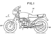
- the motorcycle M has its multi-cylinder internal combustion engine E mounted on a body frame 1 between front and rear wheels Wf, Wr.
- the engine E is screwed at one position a to the lower end part of a down tube 1d and at two upper and lower positions b, c to a centre tube 1c; i.e., at three positions in total.
- the engine E has two crankshafts 2 1 , 2 2 which are arranged to be parallel with and laterally spaced from a longitudinal axis of the motor cycle M through the same distance.
- the crankshaft 2 1 on the left side L of the vehicle and the crankshaft 2 2 on the right side R thereof will be referred to as a first crankshaft and a second crankshaft, respectively.
- First and second pistons 4 1 , 4 2 are operatively connected to the first and second crankshafts 2 1 , 2 2 through first and second connecting rods 3 1 , 3 2 , respectively.
- First and second cylinders 5 1 , 5 2 for slidably accommodating therein the pistons 4 1 , 4 2 , respectively, are arranged adjacent to each other in the axial direction of the crankshafts 2 1 , 2 2 such that the cylinders are inclined or laid in the direction approaching to each other.
- the cylinders 5 1 , 5 2 are arranged side by side in a substantially horizontal direction as shown, or to cross each other to form an X figure as a whole.
- the second cylinder 5 2 is arranged near the front side F of the vehicle relative to the first cylinder 5 1 . Meanwhile, a transmission T is disposed under a plane connecting between the axes of the crankshafts 2 1 and 2 2 .
- a body 6 of the engine E is composed of a central block 6c and left-hand and right-hand blocks 61, 6r, which are abutted with left and right ends of the central block through gaskets 7, 7 and secured thereto by a plurality of bolts 8, respectively.
- the central block 6c forms therein the first and second cylinders 5 1 , 5 2 .
- the right-hand block 6r is integrally formed with a first cylinder head 10 1 defining a first combustion chamber 9 1 together with the first piston 4 1 therebetween and a second crankcase 11 2 for accommodating the second crankshaft 2 2 in cooperation with the central block 6c.
- the left-hand block 61 is integrally formed with a second cylinder head 10 2 defining a second combustion chamber 9 2 together with the second piston 4 2 therebetween and a first crankcase 11 1 for accommodating the first crankshaft 2 1 in cooperation with the central block 6c.
- the left-hand and right-hand blocks 61, 6r are formed to have the same configuration for inter- changability.
- two pairs of semicircular bearing walls 13 1 , 13 1 ; 14 1 , 14 1 for holding therebetween a pair of bearings 12 1 , 12 1 mounted at both ends of the first crankshaft 2 1 are formed in the opposed surfaces of the central block 6c and the first crankcase 11 1 , respectively
- two pairs of semicircular bearing walls 13 2 , 13 2 ; 14 2 , 14 2 for holding therebetween a pair of bearings 12 2 , 12 2 mounted on both ends of the second crankshaft 2 2 are formed in the opposed surfaces of the central block 6c and the second crankcase 11 2 , respectively.
- intake ports 15 1 , 15 2 In the cylinder heads 10 1 , 10 2 are formed intake ports 15 1 , 15 2 and exhaust ports 16 1 , 16 2 communicating with the corresponding combustion chambers 9 1 , 9 2 , respectively.
- the intake ports 15 1 , 15 2 have inlets opened upwardly and the exhaust ports 16 1 , 16 2 have outlets opened downwardly, so that intake air and exhaust gas are caused to flow in the form of a crossing flow (see Fig. 2).
- Carburetors 17 1 , 17 2 are mounted to the inlets of the intake ports 15 1 , 15 2 , respectively. These intake ports 15 1 , 15 2 and carburetors 17 1 , 17 2 constitute two separate intake systems 18 1 , 18 2 and, by utilizing a space 19 between the intake systems 18 1 , 18 2 , a starting motor 20 is disposed with its drive shaft 20a extending parallel to the crankshafts 2 1 , 2 2 .
- the starting motor 20 is located at the top apex of a substantially equilateral triangle having its base formed of a straight line connecting between the axes of both the crankshafts 2 1 , 2 2 , and the motor is placed on an installation surface 21, which is formed at the upper central part of the central block 6c to provide an elevated stand, and is then fixed thereto by means of bolts 22.
- Intake and exhaust valves 23 1 , 23 2 ; 24 1 , 24 2 for opening and closing the intake and exhaust ports 15 1 , 15 2 ; 16 1 , 16 2 , respectively, are mounted in the corresponding cylinder heads 10 1 , 10 2 and are biassed in the valve-closing direction by means of valve springs 25 1 , 25 2 ; 26 1 , 26 2 , respectively.
- valve heads 10 1 , 10 2 are interposed through packings 29, 29 head covers 28 1 , 28 2 for defining valve actuating chambers 27 1 , 27 2 therebetween, and are secured thereto by a plurality of bolts (not shown).
- valve actuating chambers 27 1 , 27 2 there are installed valve actuating devices 30 1 , 30 2 for causing the intake and exhaust valves 23 1 , 23 2 ; 24 1 , 24 2 to open, respectively.
- cam shafts 31 1 , 31 2 arranged parallel to the crankshafts 2 1 , 2 2 are held between the cylinder heads 10 1 , 10 2 and the head covers 28 1 , 28 2 through two pairs of bearings 32 1 , 32 1 ; 32 2 , 32 2 .
- Intake rocker arms 33i, 33i are disposed between the intake cams 31 i, 31 i of the cam shafts 31 1 , 31, and the intake valves 23 1 , 23 2 so as to bridge therebetween, whereas exhaust rocker arms 33e, 33e are disposed between exhaust cams 31 e, 31e and the exhaust valves 24 1 , 24 2 so as to bridge therebetween.
- rocker arms 33i, 33e are pivotably supported on rocker shafts 34i, 34e which in turn are supported on the corresponding head covers 28 1 , 28 2 .
- the cam shaft 31 1 on the first cylinder head 10 1 side will be referred to as a first cam shaft
- the cam shaft 31 2 on the second cylinder head 10 2 side will be referred to as a second cam shaft.
- a gearing chamber 35 extending from one head cover 28 1 to the other head cover 28 2 while passing between both the cylinders 5 1 and 5 2 .
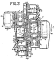
- the crankshafts 2 1 , 2 2 are interlocked with each other in the gearing chamber 35 through a synchronizing device 36 so as to be rotated synchronously.
- the synchronizing device 36 comprises first and second drive gears 37 1 , 37 2 of the same diameter fixed to the crankshafts 2 1 , 2 2 , respectively, and a driven gear 38 having a larger diameter than those drive gears 37 1 , 37 2 and meshing therewith.
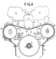
- the second crankshaft 2 2 is interlocked with the first cam shaft 31, through a first timing device 39 1
- the first crankshaft 2 1 is interlocked with the second cam shaft 31 2 through a second timing device 39 2
- the first timing device 39 comprises the second drive gear 37 2 and a timing gear 40 1 , which gear 40, is secured to the first cam shaft 31 1 , meshes with the drive gear 37 2 and has two times more the number of gear teeth than the drive gear 37 2
- the second timing device 39 2 comprises the first drive gear 37 1 and a timing gear 40 2 , which gear 40 2 is secured to the second cam shaft 31 2 , meshes with the drive gear 37 1 and has two times more the number of gear teeth than the drive gear 37 1
- the first and second drive gears 37 1 , 37 2 serve as common components for the synchronizing device 36 as well as the first and second timing devices 39 1 , 39 2 .
- each of the timing gears 40 1 , 40 2 is divided into two gears 40a, 40b slightly rotatable relative to each other, and an elastic member 41 is interposed between both the gears 40a and 40b to produce a resilient force for shifting the phase therebetween.
- the driven gear 38 is divided into an outer wheel 38a on the teeth side and an inner wheel 38b on the boss side which wheels are rotatable relative to each other within a specified range, and a torque damper member 42 capable of deforming upon receipt of the rotation torque larger than a predetermined value is interposed between those wheels 38a and 38b.
- the inner wheel 38b of the driven gear 38 is spline-coupled to the rear end of the hollow drive shaft 43 which extends from the transmission chamber 35 parallel to the crankshafts 2 1 , 2 2 while passing through the front half of the central block 6c, and an input member of a multi-plate friction clutch 44, i.e., a clutch outer 44a, is spline-coupled to the front end of the drive shaft 43.
- a clutch outer 44a is spline-coupled to the front end of the drive shaft 43.
- the clutch 44 is located in the foremost part of the engine F in the direction toward the vehicle head. Accordingly, there are obtained advantages that the clutch 44 is favorably cooled by effectively receiving travelling winds, and that the space produced just behind the front wheel Wf can be utilized to check and repair the clutch 44 with ease.
- the drive shaft 43 has its front end part supported on the central block 6c through a bearing 45 and its rear end part supported on a later-described transmission input shaft 49 through a bearing tube 46 fitted in the hollow portion of the drive shaft.
- crankshafts 2 1 , 2 2 are arranged to have their axes located within a triangle A (see Fig. 2) connecting three axes of both the cam shafts 31 1 , 31 2 and the output shaft 43. More specifically, when the crankshafts 2 1 , 2 2 are both arranged on the base a of the triangle A, i.e, a straight line connecting two axes of the cam shafts 31 1 , 31 2 , the cylinders 5 1 , 5 2 come into a horizontal arrangement.
- first and second crankshafts 2 1 , 2 2 are arranged on two oblique sides b, c of the triangle A, i.e., on a straight line b connecting two axes of the second cam shaft 31 2 and the output shaft 43 and on a straight line c connecting two axes of the first cam shaft 31 1 and the output shaft 43, respectively, or when the crankshafts 2 1 , 2 2 are both arranged inside the triangle, the cylinders 5 i , 5 2 come into an X type arrangement.
- a transmission case 48 defining a speed change chamber 47 therebetween, in which there is installed a transmission T. More specifically, transmission input and output shafts 49, 50 are disposed in parallel to the crankshafts 21,22, and multi-staged gear trains 51 1 , 52 2 ... 51 n are fitted over both the shafts 49, 50 to provide different speed change ratios.
- the transmission input shaft 49 is held between the central block 6c and the transmission case 48 through a pair of front and rear bearings 52, 52', whereas the transmission output shaft 50 is supported on the transmission case 48 through a pair of front and rear bearings 53, 53'.
- the transmission input shaft 49 is formed long to have its front end extending through the bearing tube 46 fitted in the hollow portion of the drive shaft 43 and projecting out of the front end face of the drive shaft 43, to which front end is spline-coupled an output member of the clutch 44, i.e., clutch inner 44b.
- the rear end of the transmission output shaft 50 projecting out of the rear surface of the transmission case 48 is coupled through a torque damper mechanism 55 with a final output shaft 54 for driving a propeller shaft (not shown) to drive the rear wheel of the motorcycle M.
- an AC power generator 56 is provided, of which rotor 57 has an end plate 57a taper-fitted over the rear end of the first crankshafts 2 1 and fixed thereto by means of a bolt 58.
- a starting reduction gearing 59 for amplifying and transmitting the starting torque of the starting motor 20 to the first crankshaft 2 1 .
- An output gear 59a of the reduction gearing 59 is fitted over the first crankshaft 2 1 rotatably relative to each other and coupled to the end plate 57a through a roller type overrunning clutch 60.
- An oil pump 64 for pumping lubricating oil stored in the transmission case 48 to be supplied to respective motional parts of the engine E is installed within the transmission case 48 as shown in Fig. 2, and an oil pump drive gear 65 for driving the oil pump 64 is located adjacent the driven gear 38 and secured to the rear end of the drive shaft 43, as shown in Fig. 5.
- Fig. 5 designated at 66f is a front cover secured to the front surface of the central block 6c for covering the clutch 44, and at 66r is a rear cover secured to the rear surface of the central block 6c for covering the starting reduction gearing 59, the power generator 56 and the torque damper mechanism 55.
- first and second pistons 4 1 , 4 2 are moved in the opposite directions, and the first and second crankshafts 2 1 , 2 2 are coupled with each other through the synchronizing device 36 so that they are synchronously rotated in the same direction.
- crankshafts 2 1 , 2 2 are both arranged on the base a of the triangle A, and the cylinders 5 1 , 5 2 are both arranged to be horizontal or substantially horizontal, causes by itself all or almost of not only the primary inertial force but also the secondary inertial force in the first and second piston 4 1 , 4 2 systems to be well balanced, thereby eliminating or significantly alleviating vibrations due to those inertial forces, like the conventional horizontally opposed type engines.
- first and second crankshafts 2 1 , 2 2 are arranged on two oblique sides b, c of the triangle A, respectively, or they are both arranged inside the triangle A so as to bring the first and second cylinders 5 1 , 5 2 into the X type array, it becomes possible to eliminate or significantly alleviate vibrations due to the primary inertial force, like conventional V type engines, just by properly selecting phases of the first and second pistons 4 1 , 4 2 and attaching balancer weights to the first and second crankshafts 2 1 , 2 2 in appropriate positions.
- the total width of the engine in this case is reduced as compared with the V type engine.
- the distances between the adjacent axes of the second cam shaft 31 2 , the first crankshaft 2 1 and the output shaft 43 as well as between the axes of the first cam shaft 31 1 , the second crankshaft 2 2 and the output shaft 43 can be minimized permitting the timing devices 39 1 , 39 2 and the synchronizing device 36 to be all made compact.
- the inter-axis distances between the first crankshaft 2 1 and the second cam shaft 31 2 as well as between the second crankshaft 2 2 and the first cam shaft 31, become each shorter than the inter-axis distance between the crankshaft and the cam shaft belonging to the same system, because of adjacent arrangement of the cylinders 5 1 , 5 2 in the axial direction of the crankshafts.
- the timing device connecting each pair of the above shafts can be constituted to have a smaller size correspondingly.
- the starting motor 20 when the starting motor 20 is actuated to put in service the engine E, the starting torque of the drive shaft 20a of the motor 20 is amplified by the starting reduction gearing 58 to be transmitted to the first crankshaft 2 1 through the overrunning clutch 60 and the end plate 57a of the motor 57 and also to the second crankshaft 2 2 through the synchronizing device 36, thereby cranking both the crankshafts 2 1 and 2 2 simultaneously so that the engine E .can be started up.
- the starting motor 20 is arranged to locate at the top apex of a substantially equilateral triangle having a base thereof formed of a straight line connecting the axes of both the crankshafts 2 1 , 2 2 so that the starting motor 20 of relatively large weight assumes a position just above the center of gravity of the engine E and the lateral weight balance of the engine E is ensured when loaded on the vehicle.
- the first and second crankshafts 2 1 , 2 2 are rotated synchronously to drive the driven gear 38 through the drive gears 37 1 , 37 2 with a certain reduction ratio, respectively.
- the rotation torque of the driven gear 38 is transmitted through the drive shaft 43, the clutch 44 and the transmission input shaft 49 in sequence to reach the transmission output shaft 50 and the final output shaft 54 through one gear train selected out of multi-staged gear trains 51 1 -51 n .
- the output torque is further transmitted through a not-shown propeller shaft to the rear wheel Wr of the motorcycle M to drive the same. Relatively large torque fluctuations produced during such transmission are effectively absorbed with the damping action of the torque damper mechanism 55 as well as the torsional actions of the drive shaft 43 and the transmission input shaft 49.
- the drive shaft 43 and the transmission input shaft 49 are both formed long to penetrate through the front half of the central block 6c and fitted to each other with their front ends coupled via the clutch 44, whereby in practice the transmitting shaft has a length corresponding to two times the section of the central block 6c through which both the shafts penetrate, thus providing an effective torsional action.
- the synchronizing device 36 can interlock both the crankshafts 2 1 , 2 2 together in synchronous relation without suffering any interference from those cylinders 5 1 , 5 2 . Furthermore, since the large diameter driven gear 38 of the synchronizing device 36 is secured to the drive shaft 43 disposed under the first and second cylinders 5 1 , 5 2 , outputs of the crankshafts 2 1 , 2 2 can be taken out to the exterior without encountering any obstruction from the cylinders 5 1 , 5 2 and, on this occasion, the synchronizing device 36 functions also as a speed reduction device.
- the transmission T composed of the transmission input and output shafts 49, 50 and the gear trains 51 1 ⁇ 51 n is disposed right under the central block 6c, the lateral weight balance of the engine E when loaded on the vehicle will not be lost even with the transmission T having a large weight. Also, the transmission T has no part laterally extending that of the engine E, so that the lateral banking operation of the motorcycle M will not be restricted.
- first and second crankshafts 2 1 , 2 2 rotate the second and first cam shafts 31 2 , 31, of their opposite systems through the second and first timing devices 39 2 , 39 1 , respectively, thereby operating the valve actuating devices 30 1 , 30 2 to open and close the intake and exhaust valves 23 1 , 24 1 ; 23 2 , 24 2 .
- the inter-axis distances between the first crankshaft 2 1 and the second cam shaft 31 2 as well as between the second crankshaft 2 2 and the first cam shaft 31, interlocked with each other through the timing devices 39 1 , 39 2 , respectively, are each shorter than the inter-axis distance between the crankshaft and the cam shaft belonging to the same system because of the above-mentioned arrangement of the cylinders 5 1 , 5 2 , whereby each of the timing devices 39 1 , 39 2 can be constituted to have a smaller size and errors in timing of opening and closing operations of the valves can be made smaller correspondingly.
- the synchronizing device 36 and the timing devices 39 1 , 39 2 are constituted in the form of gears, they may be in the form of chains or belts. In some cases, the synchronizing device 36 may be arranged to rotate the crankshafts 2 1 , 2 2 in the opposite directions from each other.
Landscapes
- Engineering & Computer Science (AREA)
- Chemical & Material Sciences (AREA)
- Combustion & Propulsion (AREA)
- Mechanical Engineering (AREA)
- General Engineering & Computer Science (AREA)
- Cylinder Crankcases Of Internal Combustion Engines (AREA)
Claims (16)
caractérisé par le fait que lesdits premier et second cylindres (51, 52) sont décalés l'un de l'autre dans le sens axial desdits vilebrequins (21, 22), l'un (52) de ces cylindres étant situé directement derrière l'autre (51) desdits cylindres dans le sens axial des vilebrequins; par le fait que chaque vilebrequin précité (21, 22) associé à l'un desdits cylindres (51, 52), et son arbre à cames adjacent (312, 311) associé à l'autre des cylindres (51, 52), sont mutuellement décalés pour l'essentiel dans une direction de coulissement des pistons (41, 42) dans les cylindres (51, 52); et par le fait que le dispositif de synchronisation (36) est interposé entre lesdits premier et second cylindres (51, 52) dans le sens axial des vilebrequins (21, 22).
Applications Claiming Priority (18)
| Application Number | Priority Date | Filing Date | Title |
|---|---|---|---|
| JP50066/84 | 1984-03-15 | ||
| JP5006384A JPS60192832A (ja) | 1984-03-15 | 1984-03-15 | 多気筒内燃機関 |
| JP5006284A JPS60192831A (ja) | 1984-03-15 | 1984-03-15 | 多気筒内燃機関 |
| JP5006184A JPS60192830A (ja) | 1984-03-15 | 1984-03-15 | 多気筒内燃機関 |
| JP50061/84 | 1984-03-15 | ||
| JP50068/84 | 1984-03-15 | ||
| JP5006784A JPS60192835A (ja) | 1984-03-15 | 1984-03-15 | 車両用多気筒内燃機関 |
| JP5006884A JPS60192836A (ja) | 1984-03-15 | 1984-03-15 | 多気筒内燃機関 |
| JP5006584A JPS60192833A (ja) | 1984-03-15 | 1984-03-15 | 多気筒内燃機関 |
| JP50065/84 | 1984-03-15 | ||
| JP5006484A JPS60192829A (ja) | 1984-03-15 | 1984-03-15 | 内燃機関及び変速機の組立体 |
| JP50064/84 | 1984-03-15 | ||
| JP5006684A JPS60192834A (ja) | 1984-03-15 | 1984-03-15 | 多気筒内燃機関 |
| JP50067/84 | 1984-03-15 | ||
| JP50063/84 | 1984-03-15 | ||
| JP50062/84 | 1984-03-15 | ||
| JP20589884A JPS60195331A (ja) | 1984-10-01 | 1984-10-01 | O.h.c型多気筒内燃機関 |
| JP205898/84 | 1984-10-01 |
Publications (3)
| Publication Number | Publication Date |
|---|---|
| EP0158453A2 EP0158453A2 (fr) | 1985-10-16 |
| EP0158453A3 EP0158453A3 (en) | 1986-12-30 |
| EP0158453B1 true EP0158453B1 (fr) | 1990-02-07 |
Family
ID=27576997
Family Applications (1)
| Application Number | Title | Priority Date | Filing Date |
|---|---|---|---|
| EP85301778A Expired EP0158453B1 (fr) | 1984-03-15 | 1985-03-14 | Moteur polycylindrique à combustion interne |
Country Status (4)
| Country | Link |
|---|---|
| US (1) | US4685428A (fr) |
| EP (1) | EP0158453B1 (fr) |
| AU (1) | AU562848B2 (fr) |
| DE (1) | DE3575972D1 (fr) |
Families Citing this family (13)
| Publication number | Priority date | Publication date | Assignee | Title |
|---|---|---|---|---|
| DE3541315A1 (de) * | 1985-11-22 | 1987-05-27 | Bayerische Motoren Werke Ag | Anordnung von wellen und aggregaten bei mehrzylinder-hubkolbenmaschinen mit gesonderten gaswechsel-steuervorrichtungen, insbesondere brennkraftmaschinen |
| WO1987006304A1 (fr) * | 1986-04-11 | 1987-10-22 | Bennett Automotive Technology Pty. Ltd. | Moteur a combustion interne avec ligne de separation du carter et de la culasse au milieu du bloc cylindre |
| JPH09287464A (ja) * | 1996-04-24 | 1997-11-04 | Suzuki Motor Corp | 自動二輪車用4サイクルv型エンジンのシリンダヘッド |
| US6250263B1 (en) | 1999-04-28 | 2001-06-26 | Mark Sisco | Dual piston cylinder configuration for internal combustion engine |
| DE10006690C1 (de) * | 2000-02-15 | 2001-06-28 | Ktm Sportmotorcycle Ag Mattigh | Startvorrichtung für einen Zweizylinderverbrennungsmotor in V-Anordnung |
| US7588010B2 (en) * | 2007-04-16 | 2009-09-15 | Yamaha Hatsudoki Kabushiki Kaisha | Power unit for a vehicle |
| US8256561B2 (en) * | 2007-04-16 | 2012-09-04 | Yamaha Hatsudoki Kabushiki Kaisha | Vehicle |
| US8905801B1 (en) | 2007-12-31 | 2014-12-09 | Brp Us Inc. | Marine outboard motor |
| JP5049164B2 (ja) * | 2008-02-20 | 2012-10-17 | 本田技研工業株式会社 | トルクダンパを備える車両 |
| ITSP20120003A1 (it) * | 2012-01-27 | 2013-07-28 | Mattia Colombo | Motore a ciclo otto o diesel a v pluricilindrico con angoli di manovella variabili da o° ad oltre 180°. |
| ITRM20130356A1 (it) * | 2013-06-21 | 2014-12-22 | Ingranaggio Di Marco De Martino | Motore a combustione interna volumetrico alternativo di tipo compatto. |
| DE102014115041A1 (de) * | 2014-10-16 | 2016-04-21 | Obrist Technologies Gmbh | Stromaggregat |
| EP3631183A1 (fr) * | 2017-06-02 | 2020-04-08 | Achates Power, Inc. | Réduction du bruit, des vibrations et de la dureté dans un moteur à pistons opposés |
Family Cites Families (14)
| Publication number | Priority date | Publication date | Assignee | Title |
|---|---|---|---|---|
| US497239A (en) * | 1893-05-09 | Gas-engine | ||
| US1361619A (en) * | 1919-07-02 | 1920-12-07 | Roos Charles Johannes | Internal-combustion engine |
| GB162797A (en) * | 1920-02-05 | 1921-05-05 | George Pinder | Improvements in four stroke cycle internal combustion engines |
| CH103509A (de) * | 1922-08-23 | 1924-02-16 | Harald Knudsen Carl | Zweitaktverbrennungskraftmaschine. |
| US1816406A (en) * | 1927-08-20 | 1931-07-28 | Spencer Aircraft Motors Inc | Aeroplane engine |
| US2387843A (en) * | 1942-07-01 | 1945-10-30 | Gray Agnes | Locomotive power drive |
| CH241506A (de) * | 1943-06-01 | 1946-03-15 | Ringhoffer Tatra Werke Ag | Brennkraftmaschine mit zwei Reihen zueinander paralleler Zylinder und zwei Kurbelwellen. |
| FR910529A (fr) * | 1945-04-27 | 1946-06-11 | Moteur polycylindrique | |
| FR1230454A (fr) * | 1957-07-09 | 1960-09-15 | Moteur à combustion interne, notamment pour véhicule automobile | |
| US3384058A (en) | 1967-04-21 | 1968-05-21 | Brunswick Corp | Overhead camshaft engine |
| GB1149988A (en) * | 1967-09-06 | 1969-04-23 | Ametek Inc | Combinations of two or more internal combustion engines |
| US4331111A (en) * | 1979-09-10 | 1982-05-25 | Bennett Arthur G | Low vibration engine |
| JPS57159927A (en) | 1981-03-25 | 1982-10-02 | Honda Motor Co Ltd | Multi-cylinder engeine |
| US4470379A (en) * | 1981-03-25 | 1984-09-11 | Honda Giken Kogyo Kabushiki Kaisha | Multi-cylinder engine |
-
1985
- 1985-03-13 AU AU39810/85A patent/AU562848B2/en not_active Ceased
- 1985-03-14 EP EP85301778A patent/EP0158453B1/fr not_active Expired
- 1985-03-14 DE DE8585301778T patent/DE3575972D1/de not_active Expired - Lifetime
- 1985-03-15 US US06/712,267 patent/US4685428A/en not_active Expired - Fee Related
Also Published As
| Publication number | Publication date |
|---|---|
| EP0158453A3 (en) | 1986-12-30 |
| AU562848B2 (en) | 1987-06-18 |
| DE3575972D1 (de) | 1990-03-15 |
| US4685428A (en) | 1987-08-11 |
| EP0158453A2 (fr) | 1985-10-16 |
| AU3981085A (en) | 1985-09-19 |
Similar Documents
| Publication | Publication Date | Title |
|---|---|---|
| US5099945A (en) | Engine unit for vehicle | |
| EP0408335B1 (fr) | Système d'équilibrage pour moteur à combustion interne | |
| US11492962B2 (en) | Power generation device and automobile | |
| US5184582A (en) | Engine unit for vehicle | |
| US4685428A (en) | Multi-cylinder internal combustion engine | |
| US20030005894A1 (en) | Radial internal combustion engine with floating balanced piston | |
| US4470379A (en) | Multi-cylinder engine | |
| US5044333A (en) | Balancing arrangement for internal combustion engine | |
| US6807927B2 (en) | Piston engine with counterrotating crankshafts | |
| EP1384859B1 (fr) | Moteur à combustion interne | |
| JPH0475364B2 (fr) | ||
| US6848411B2 (en) | Secondary balancer of vertical engine of outboard motor | |
| CN100540876C (zh) | 一种八缸热气机传动系统 | |
| JPH0454047B2 (fr) | ||
| JPS60192829A (ja) | 内燃機関及び変速機の組立体 | |
| JP2006125257A (ja) | 並列多気筒4サイクルエンジン及び鞍乗型車両 | |
| JPH0480215B2 (fr) | ||
| JPS62107238A (ja) | 車両用多気筒内燃機関 | |
| JPS60192836A (ja) | 多気筒内燃機関 | |
| JPH0522053B2 (fr) | ||
| JPH0472979B2 (fr) | ||
| JPS62233424A (ja) | 多気筒内燃機関 | |
| JPS60192832A (ja) | 多気筒内燃機関 | |
| JPS60192835A (ja) | 車両用多気筒内燃機関 | |
| JP4578374B2 (ja) | 車両用動力装置 |
Legal Events
| Date | Code | Title | Description |
|---|---|---|---|
| PUAI | Public reference made under article 153(3) epc to a published international application that has entered the european phase |
Free format text: ORIGINAL CODE: 0009012 |
|
| AK | Designated contracting states |
Designated state(s): DE FR GB IT |
|
| PUAL | Search report despatched |
Free format text: ORIGINAL CODE: 0009013 |
|
| AK | Designated contracting states |
Kind code of ref document: A3 Designated state(s): DE FR GB IT |
|
| 17P | Request for examination filed |
Effective date: 19870623 |
|
| 17Q | First examination report despatched |
Effective date: 19871228 |
|
| RAP1 | Party data changed (applicant data changed or rights of an application transferred) |
Owner name: HONDA GIKEN KOGYO KABUSHIKI KAISHA |
|
| ITF | It: translation for a ep patent filed | ||
| GRAA | (expected) grant |
Free format text: ORIGINAL CODE: 0009210 |
|
| AK | Designated contracting states |
Kind code of ref document: B1 Designated state(s): DE FR GB IT |
|
| PGFP | Annual fee paid to national office [announced via postgrant information from national office to epo] |
Ref country code: GB Payment date: 19900228 Year of fee payment: 6 |
|
| REF | Corresponds to: |
Ref document number: 3575972 Country of ref document: DE Date of ref document: 19900315 |
|
| PGFP | Annual fee paid to national office [announced via postgrant information from national office to epo] |
Ref country code: FR Payment date: 19900323 Year of fee payment: 6 |
|
| ITTA | It: last paid annual fee | ||
| ET | Fr: translation filed | ||
| PLBE | No opposition filed within time limit |
Free format text: ORIGINAL CODE: 0009261 |
|
| STAA | Information on the status of an ep patent application or granted ep patent |
Free format text: STATUS: NO OPPOSITION FILED WITHIN TIME LIMIT |
|
| 26N | No opposition filed | ||
| PG25 | Lapsed in a contracting state [announced via postgrant information from national office to epo] |
Ref country code: GB Effective date: 19910314 |
|
| GBPC | Gb: european patent ceased through non-payment of renewal fee | ||
| PG25 | Lapsed in a contracting state [announced via postgrant information from national office to epo] |
Ref country code: FR Effective date: 19911129 |
|
| REG | Reference to a national code |
Ref country code: FR Ref legal event code: ST |
|
| PGFP | Annual fee paid to national office [announced via postgrant information from national office to epo] |
Ref country code: DE Payment date: 19950309 Year of fee payment: 11 |
|
| PG25 | Lapsed in a contracting state [announced via postgrant information from national office to epo] |
Ref country code: DE Effective date: 19961203 |