EP0159570A1 - Méthode de contrôle d'une machine à copier - Google Patents
Méthode de contrôle d'une machine à copier Download PDFInfo
- Publication number
- EP0159570A1 EP0159570A1 EP85103718A EP85103718A EP0159570A1 EP 0159570 A1 EP0159570 A1 EP 0159570A1 EP 85103718 A EP85103718 A EP 85103718A EP 85103718 A EP85103718 A EP 85103718A EP 0159570 A1 EP0159570 A1 EP 0159570A1
- Authority
- EP
- European Patent Office
- Prior art keywords
- fusing
- copying
- wait
- temperature
- fusing device
- Prior art date
- Legal status (The legal status is an assumption and is not a legal conclusion. Google has not performed a legal analysis and makes no representation as to the accuracy of the status listed.)
- Granted
Links
- 238000000034 method Methods 0.000 title claims abstract description 8
- 238000010438 heat treatment Methods 0.000 claims abstract description 23
- 238000012545 processing Methods 0.000 description 8
- 230000002950 deficient Effects 0.000 description 7
- 108091008695 photoreceptors Proteins 0.000 description 6
- 230000003287 optical effect Effects 0.000 description 4
- 230000000717 retained effect Effects 0.000 description 4
- 238000013461 design Methods 0.000 description 2
- 238000010586 diagram Methods 0.000 description 2
- 238000005192 partition Methods 0.000 description 2
- 238000000926 separation method Methods 0.000 description 2
- 238000012546 transfer Methods 0.000 description 2
- 239000004809 Teflon Substances 0.000 description 1
- 229920006362 Teflon® Polymers 0.000 description 1
- 229910052782 aluminium Inorganic materials 0.000 description 1
- XAGFODPZIPBFFR-UHFFFAOYSA-N aluminium Chemical compound [Al] XAGFODPZIPBFFR-UHFFFAOYSA-N 0.000 description 1
- 210000000078 claw Anatomy 0.000 description 1
- 230000004927 fusion Effects 0.000 description 1
- 239000011521 glass Substances 0.000 description 1
- 239000000463 material Substances 0.000 description 1
- 229910052751 metal Inorganic materials 0.000 description 1
- 239000002184 metal Substances 0.000 description 1
- 238000012986 modification Methods 0.000 description 1
- 230000004048 modification Effects 0.000 description 1
- 230000002093 peripheral effect Effects 0.000 description 1
- 230000000630 rising effect Effects 0.000 description 1
- 229920002379 silicone rubber Polymers 0.000 description 1
- 239000004945 silicone rubber Substances 0.000 description 1
Images


Classifications
-
- G—PHYSICS
- G03—PHOTOGRAPHY; CINEMATOGRAPHY; ANALOGOUS TECHNIQUES USING WAVES OTHER THAN OPTICAL WAVES; ELECTROGRAPHY; HOLOGRAPHY
- G03G—ELECTROGRAPHY; ELECTROPHOTOGRAPHY; MAGNETOGRAPHY
- G03G15/00—Apparatus for electrographic processes using a charge pattern
- G03G15/20—Apparatus for electrographic processes using a charge pattern for fixing, e.g. by using heat
-
- G—PHYSICS
- G03—PHOTOGRAPHY; CINEMATOGRAPHY; ANALOGOUS TECHNIQUES USING WAVES OTHER THAN OPTICAL WAVES; ELECTROGRAPHY; HOLOGRAPHY
- G03G—ELECTROGRAPHY; ELECTROPHOTOGRAPHY; MAGNETOGRAPHY
- G03G15/00—Apparatus for electrographic processes using a charge pattern
- G03G15/20—Apparatus for electrographic processes using a charge pattern for fixing, e.g. by using heat
- G03G15/2003—Apparatus for electrographic processes using a charge pattern for fixing, e.g. by using heat using heat
-
- G—PHYSICS
- G03—PHOTOGRAPHY; CINEMATOGRAPHY; ANALOGOUS TECHNIQUES USING WAVES OTHER THAN OPTICAL WAVES; ELECTROGRAPHY; HOLOGRAPHY
- G03G—ELECTROGRAPHY; ELECTROPHOTOGRAPHY; MAGNETOGRAPHY
- G03G15/00—Apparatus for electrographic processes using a charge pattern
- G03G15/20—Apparatus for electrographic processes using a charge pattern for fixing, e.g. by using heat
- G03G15/2003—Apparatus for electrographic processes using a charge pattern for fixing, e.g. by using heat using heat
- G03G15/2014—Apparatus for electrographic processes using a charge pattern for fixing, e.g. by using heat using heat using contact heat
- G03G15/2039—Apparatus for electrographic processes using a charge pattern for fixing, e.g. by using heat using heat using contact heat with means for controlling the fixing temperature
-
- G—PHYSICS
- G03—PHOTOGRAPHY; CINEMATOGRAPHY; ANALOGOUS TECHNIQUES USING WAVES OTHER THAN OPTICAL WAVES; ELECTROGRAPHY; HOLOGRAPHY
- G03G—ELECTROGRAPHY; ELECTROPHOTOGRAPHY; MAGNETOGRAPHY
- G03G15/00—Apparatus for electrographic processes using a charge pattern
- G03G15/20—Apparatus for electrographic processes using a charge pattern for fixing, e.g. by using heat
- G03G15/2003—Apparatus for electrographic processes using a charge pattern for fixing, e.g. by using heat using heat
- G03G15/2014—Apparatus for electrographic processes using a charge pattern for fixing, e.g. by using heat using heat using contact heat
- G03G15/2039—Apparatus for electrographic processes using a charge pattern for fixing, e.g. by using heat using heat using contact heat with means for controlling the fixing temperature
- G03G15/205—Apparatus for electrographic processes using a charge pattern for fixing, e.g. by using heat using heat using contact heat with means for controlling the fixing temperature specially for the mode of operation, e.g. standby, warming-up, error
Definitions
- the present invention relates to a controlling method of a copying machine, more particularly, to a method for controlling the copying machine by the temperatures of a fusing device keeping it in a wait-reset state which is capable of the copying operation and in a wait state for preheating which is incapable of the copying operation.
- the controlling method in accordance with the present invention is in a copying machine comprising a fusing device which, by rotating a heating roller and a press roller in a mutually forcible contact, fuses a toner image on the copying paper passing through the rollers, that the machine is provided with a wait-reset state capable of the copying operation and a wait state incapable of the copying operation by means of the conditions of the fusing device.
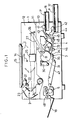
- Figure 1 is a longitudinal sectional view clearly showing internal structure of a copying machine of a type having a movable optical system.
- the inside of the copying machine body (1) is divided into an upper chamber (12) and the lower chamber (13) by a partition (11), wherein the optical system (2) is provided in the upper chamber (12) and the copy processing section (3) and a conveying section (4) of the copying papers are provided in the lower chamber (13).
- the optical system (2) comprising a light source (21), No. 1 reflector (22), No. 2 reflector (23), No. 3 reflector (24), a lens (25) and No.
- the copy processing section (3) is provided with an corona charger (32), a developing means (33), a transfer charger (34), a separation charger (35) and a cleaner (36) arranged in that order in the peripheral of the photoreceptor drum (31), which rotates on every copying operation in a direction shown by an arrow B, wherein an electrostatic latent image corresponding to the original image is formed by the optical system (2) mentioned above after the surface of the photoreceptor drum (31) being uniformly charged by the corona charger (32) with the rotation of the photoreceptor drum (31), the electrostatic latent image is developed into a toner image by the developing means (33), the toner image is transferred onto the copying paper (P) by the transfer charger (34), the copying paper (P) is separated from the photoreceptor drum (31) by the separation charger (35) and the toner remained on the photoreceptor drum (31) is recovered by the cleaner (36).
- an electrostatic latent image corresponding to the original image is formed by the optical system (2) mentioned above after the surface
- the conveying section (4) for the copying paper comprises the feed rollers (41) (42), the paper feeding paths (43) (44), a resist roller (45), a conveying roller (46), a conveying belt (47), a fusing device (5) and a delivery roller (48) arranged in that order, wherein by selectively driving each of the feed rollers (41) and (42), the copying papers (P) are taken out one by one from the upper or the lower paper cassettes and directed toward the copy processing section (3) where the toner image is transferred thereon and delivered on the tray (18) after the toner image being heated and fused by the fusing device (5).
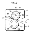
- the fusing device (5) mentioned above includes a heating roller (53) and a press roller (54) mounted rotatably to the upper and lower frames (51) (52) facing in opposition to each other vertically.
- the heating roller (53) comprises a cylindrical body (55) formed by the material such as aluminum and the like having a high heat conductivity and provided with a heating source (56) such as a heater, etc., therein, and a teflon coated layer (57) on the outer surface thereof
- the press roller (54) comprises a cylindrical body (58) formed by the metal and the like of which outer surface is provided with a silicone rubber layer (59), and by rotating at least one of two rollers by a driving means (not shown) the other roller follows the rotation reversely.
- a temperature sensor (60) such as a thermistor, etc. is provided in a contacting or adjacent state to the outer surface of the heating roller (53) together with a separating claw (61) for preventing the copying paper (P) from being rolled into the heating roller (53).
- Figure 3 shows an electric circuit diagram, which is adapted to control a key board and a controller (71) and the heat source (56) by the output signal from a control circuit (70) by connecting the resistors (62) (63) (64) and (65) in series, providing reference voltages different with each other to the comparators (66) (67) and (68) by the node voltage of each resistor, providing a same comparison voltage to the comparators (66) (67) and (68) by the node voltage of the temperature sensor (60) and the resistor (69) and impressing the output signals from each comparator (66) (67) and (68) to the control circuit (70).
- the control circuit (70) mentioned above includes a first timer for setting the time at the initial starting stage and a second timer for setting the time after the preheating.
- comparators (66) (67) and (68) impress the detecting signals to the control circuit (70) in each different detecting temperatures and the keyboard and the controller (71) and the heating source (56) may be controlled in accordance with these signals.
- the preheating mode a mode to retain the temperature of the fusing device at the setting temperature a little lower than the fusing temperature and to enable an immediate rise to the fusing temperature
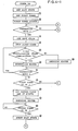
- step (5) Since the preheating mode is not attained immediately after the initial starting stage, if the timing of the first timer has reached the setting time tsl is judged at step (5), if so then as step (6) if the temperature has been reached, the setting temperature T2 for fusing is judged, if not then as step (7) if the temperature has reached the setting temperature T3 higher than T2 is judged. Then, when the temperature has not reached the setting temperature T2 or T3, the heater as the heating source (56) is energized as step (8) and when the temperature has reached the setting temperature T2 or T3 the heater is deenergized as step (9) and the wait state is reset as step (10) and the decisions and processings from step (4) onward will be repeated thereafter.
- step (4) the copying machine is set in the wait state as step (11), the timing operation of the first timer is stopped as step (12), judged as step (13) if the temperature has reached the setting temperature Tl lower than T2. If so the heater is deenergized as step (14) and if not the heater is energized as step (15) and judged again as step (16) if the preheating mode has been attained.
- step (13) onward the decisions and processings from step (13) onward will be continued.
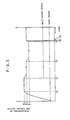
- Figure 5 shows the temperature variations of the fusing device (5) in the above operations and the variations of states between the wait state and the wait-reset state of the copying machine proper, wherein the surface temperature of the heating roller (53) rises rapidly by energizing the heater at the initial starting stage and after reaching the setting temperature T3 (e.g. 195°C) higher than the setting temperature T2 for fusion, it retains the setting temperature T3 mentioned above till the time tsl set by the first timer has past and heats the press roller (54) and so on rapidly toward the setting temperature T2. During this period, since the fusing device (5) is not heated sufficiently on the whole, the copying machine is retained in the wait state.
- the setting temperature T3 e.g. 195°C
- the heater is deenergized and cooled to the setting temperature T2 (e.g. 185°C) for fusing and retained at the setting temperature T2 thereafter.
- T2 e.g. 185°C
- the fusing device (5) is in the state sufficiently heated on the whole, the copying machine is in the wait-reset state, so the copying operation can be performed by operating a print key.
- the fusing device (5) is cooled down to the setting temperature Tl for preheating lower than the setting temperature T2 for fusing and is kept at Tl thereafter and the copying machine is retained in the wait state.
- the present invention detects the temperature rise of the fusing device at the initial starting state, sets the fixed period of time in the wait state for preheating and sets the restoring time from the wait state to the wait-reset state at the fixed time shorter than the time necessary to heat the fusing device by the time necessary for the apex of the copying paper to reach the fusing device, therefore, the copying operation can be performed only in the state which insures the stable fusing by the sufficient temperature rise and the restoring time from the wait state for preheating to the wait-reset state capable of the copying operation can be shortened.
- the present invention is not limited to the above embodiment, but various changes and modifications in designs may be made within the scope not departing from the spirit thereof, for instance, it may be possible to provide a heat source inside the press roll or split the heat source in plural numbers and operate thereof selectively to the size of the copying paper and so on.
Landscapes
- Physics & Mathematics (AREA)
- General Physics & Mathematics (AREA)
- Fixing For Electrophotography (AREA)
- Control Or Security For Electrophotography (AREA)
Applications Claiming Priority (2)
| Application Number | Priority Date | Filing Date | Title |
|---|---|---|---|
| JP64984/84 | 1984-03-30 | ||
| JP59064984A JPS60207173A (ja) | 1984-03-30 | 1984-03-30 | 複写機の制御方法 |
Publications (2)
| Publication Number | Publication Date |
|---|---|
| EP0159570A1 true EP0159570A1 (fr) | 1985-10-30 |
| EP0159570B1 EP0159570B1 (fr) | 1989-08-16 |
Family
ID=13273826
Family Applications (1)
| Application Number | Title | Priority Date | Filing Date |
|---|---|---|---|
| EP85103718A Expired EP0159570B1 (fr) | 1984-03-30 | 1985-03-28 | Méthode de contrôle d'une machine à copier |
Country Status (5)
| Country | Link |
|---|---|
| US (1) | US4671643A (fr) |
| EP (1) | EP0159570B1 (fr) |
| JP (1) | JPS60207173A (fr) |
| KR (1) | KR890004403B1 (fr) |
| DE (1) | DE3572409D1 (fr) |
Cited By (3)
| Publication number | Priority date | Publication date | Assignee | Title |
|---|---|---|---|---|
| EP0500088A3 (fr) * | 1991-02-22 | 1992-09-02 | Canon Kabushiki Kaisha | Appareil de formation d'images |
| GB2258844A (en) * | 1991-06-19 | 1993-02-24 | Asahi Optical Co Ltd | Fixing device for electrophotographic imaging apparatus. |
| US5426494A (en) * | 1992-09-18 | 1995-06-20 | Brother Kogyo Kabushiki Kaisha | Electrophotographic device and method for shortening a print time |
Families Citing this family (23)
| Publication number | Priority date | Publication date | Assignee | Title |
|---|---|---|---|---|
| US4905051A (en) * | 1985-03-12 | 1990-02-27 | Sharp Kabuhsiki Kaisha | Fixing means for electrophotographic copier |
| JPS6371048A (ja) * | 1986-09-11 | 1988-03-31 | Minolta Camera Co Ltd | 自動ペ−パ−セレクト機能を備えた電子写真複写機 |
| JPH0727476Y2 (ja) * | 1987-05-29 | 1995-06-21 | 株式会社リコー | 複写装置 |
| JPS6477079A (en) * | 1987-06-08 | 1989-03-23 | Ricoh Kk | Image processor |
| JPH0766222B2 (ja) * | 1988-05-17 | 1995-07-19 | 富士通株式会社 | トナー定着器の制御方法 |
| US5636349A (en) * | 1988-09-08 | 1997-06-03 | Indigo N.V. | Method and apparatus for imaging using an intermediate transfer member |
| DE68921005T2 (de) * | 1988-09-08 | 1995-08-31 | Indigo Nv | Fixiervorrichtung und verfahren. |
| US5157238A (en) * | 1988-09-08 | 1992-10-20 | Spectrum Sciences, B.V. | Fusing apparatus and method |
| IL111846A0 (en) * | 1994-12-01 | 1995-03-15 | Indigo Nv | Imaging apparatus and intermediate transfer blanket therefor |
| JP2946519B2 (ja) * | 1989-02-23 | 1999-09-06 | ミノルタ株式会社 | ファクシミリ装置 |
| JPH0816816B2 (ja) * | 1989-11-10 | 1996-02-21 | 旭光学工業株式会社 | ヒートローラーの温度制御装置 |
| US5815783A (en) * | 1989-12-06 | 1998-09-29 | Indigo N.V. | Method and apparatus for printing on both sides of a substrate |
| US5162855A (en) * | 1990-06-13 | 1992-11-10 | Konica Corporation | Image forming apparatus having temperature sensor for estimating the off time of the fuser as related to the platen glass temperature |
| JPH04186256A (ja) * | 1990-11-20 | 1992-07-03 | Murata Mach Ltd | 画像形成装置 |
| JPH04282653A (ja) * | 1991-03-12 | 1992-10-07 | Casio Electron Mfg Co Ltd | 画像形成装置 |
| JP2622314B2 (ja) * | 1991-03-12 | 1997-06-18 | 三田工業株式会社 | 画像形成装置 |
| JP2925366B2 (ja) * | 1991-07-17 | 1999-07-28 | キヤノン株式会社 | 画像形成装置 |
| US5321481A (en) * | 1992-08-27 | 1994-06-14 | Mathers James E | Fuser temperature and copy output controller |
| JPH06348171A (ja) * | 1993-06-04 | 1994-12-22 | Hitachi Ltd | カラー電子写真装置のローラ定着装置 |
| JPH07114292A (ja) * | 1993-10-20 | 1995-05-02 | Brother Ind Ltd | 電子写真装置 |
| JPH07114284A (ja) * | 1993-10-20 | 1995-05-02 | Brother Ind Ltd | 電子写真装置 |
| US6016410A (en) * | 1998-11-20 | 2000-01-18 | Eastman Kodak Company | Fuser for reproduction apparatus with minimized temperature droop |
| JP2001034138A (ja) * | 1999-07-19 | 2001-02-09 | Murata Mach Ltd | 画像形成装置 |
Citations (3)
| Publication number | Priority date | Publication date | Assignee | Title |
|---|---|---|---|---|
| US4144835A (en) * | 1976-11-05 | 1979-03-20 | Rank Xerox Limited | Contact heat fixing apparatus |
| EP0006553A1 (fr) * | 1978-07-03 | 1980-01-09 | International Business Machines Corporation | Procédé et appareil pour actionner une source de chaleur dans une machine à copier |
| US4425494A (en) * | 1980-06-30 | 1984-01-10 | Konishiroku Photo Industry Co., Ltd. | Heat roller fixing unit |
Family Cites Families (4)
| Publication number | Priority date | Publication date | Assignee | Title |
|---|---|---|---|---|
| US3926519A (en) * | 1974-06-03 | 1975-12-16 | Xerox Corp | Control device for an electrophotographic printing machine |
| JPS56142563A (en) * | 1980-04-07 | 1981-11-06 | Canon Inc | Fixing device |
| US4318612A (en) * | 1980-07-10 | 1982-03-09 | International Business Machines Corporation | Hot roll fuser temperature control |
| US4512649A (en) * | 1983-10-11 | 1985-04-23 | Eastman Kodak Company | Fuser apparatus |
-
1984
- 1984-03-30 JP JP59064984A patent/JPS60207173A/ja active Pending
-
1985
- 1985-03-27 US US06/716,431 patent/US4671643A/en not_active Expired - Lifetime
- 1985-03-28 DE DE8585103718T patent/DE3572409D1/de not_active Expired
- 1985-03-28 EP EP85103718A patent/EP0159570B1/fr not_active Expired
- 1985-03-29 KR KR1019850002110A patent/KR890004403B1/ko not_active Expired
Patent Citations (3)
| Publication number | Priority date | Publication date | Assignee | Title |
|---|---|---|---|---|
| US4144835A (en) * | 1976-11-05 | 1979-03-20 | Rank Xerox Limited | Contact heat fixing apparatus |
| EP0006553A1 (fr) * | 1978-07-03 | 1980-01-09 | International Business Machines Corporation | Procédé et appareil pour actionner une source de chaleur dans une machine à copier |
| US4425494A (en) * | 1980-06-30 | 1984-01-10 | Konishiroku Photo Industry Co., Ltd. | Heat roller fixing unit |
Non-Patent Citations (1)
| Title |
|---|
| IBM TECHNICAL DISCLOSURE BULLETIN, vol. 21, no. 2, July 1978, pages 481-482, New York, US; G.J. HOWARD et al.: "Copier fuser controls" * |
Cited By (4)
| Publication number | Priority date | Publication date | Assignee | Title |
|---|---|---|---|---|
| EP0500088A3 (fr) * | 1991-02-22 | 1992-09-02 | Canon Kabushiki Kaisha | Appareil de formation d'images |
| US5548378A (en) * | 1991-02-22 | 1996-08-20 | Canon Kabushiki Kaisha | Image operating apparatus providing image stabilization control |
| GB2258844A (en) * | 1991-06-19 | 1993-02-24 | Asahi Optical Co Ltd | Fixing device for electrophotographic imaging apparatus. |
| US5426494A (en) * | 1992-09-18 | 1995-06-20 | Brother Kogyo Kabushiki Kaisha | Electrophotographic device and method for shortening a print time |
Also Published As
| Publication number | Publication date |
|---|---|
| KR850006733A (ko) | 1985-10-16 |
| JPS60207173A (ja) | 1985-10-18 |
| EP0159570B1 (fr) | 1989-08-16 |
| DE3572409D1 (en) | 1989-09-21 |
| KR890004403B1 (ko) | 1989-11-03 |
| US4671643A (en) | 1987-06-09 |
Similar Documents
| Publication | Publication Date | Title |
|---|---|---|
| EP0159570B1 (fr) | Méthode de contrôle d'une machine à copier | |
| JP3403057B2 (ja) | 画像形成装置 | |
| JPH01289988A (ja) | トナー定着器の制御方法 | |
| JP3125237B2 (ja) | 画像形成装置 | |
| JPH0527643A (ja) | 定着温度制御装置 | |
| US20020164173A1 (en) | Image forming apparatus having speed-changeable image bearing body | |
| US5633704A (en) | Image forming apparatus having fixing means error detection | |
| EP1014222B1 (fr) | Appareil pour chauffer une image comprenant plusieurs éléments chauffants | |
| JPH09160408A (ja) | 画像形成装置 | |
| JPH06102718A (ja) | 電子写真装置 | |
| JPH0968885A (ja) | 加熱定着装置 | |
| JPH0199079A (ja) | 乾式電子写真装置 | |
| JPH09204115A (ja) | 画像形成装置 | |
| JP3062053B2 (ja) | 画像形成装置 | |
| JP4123147B2 (ja) | 画像形成装置 | |
| US5095329A (en) | Copying machine | |
| JPH10198215A (ja) | 画像形成装置 | |
| JPH10142999A (ja) | 定着装置及び画像形成装置並びに画像形成方法 | |
| JP2744852B2 (ja) | 加熱定着器の制御装置 | |
| JPS6243314Y2 (fr) | ||
| JPH0540527Y2 (fr) | ||
| JPS63173088A (ja) | 画像形成装置の定着装置 | |
| JPH01252984A (ja) | 熱定着装置 | |
| JPH11190958A (ja) | 定着装置 | |
| JPS6396674A (ja) | 電子写真装置 |
Legal Events
| Date | Code | Title | Description |
|---|---|---|---|
| PUAI | Public reference made under article 153(3) epc to a published international application that has entered the european phase |
Free format text: ORIGINAL CODE: 0009012 |
|
| AK | Designated contracting states |
Designated state(s): DE FR GB NL |
|
| 17P | Request for examination filed |
Effective date: 19860424 |
|
| 17Q | First examination report despatched |
Effective date: 19880420 |
|
| GRAA | (expected) grant |
Free format text: ORIGINAL CODE: 0009210 |
|
| AK | Designated contracting states |
Kind code of ref document: B1 Designated state(s): DE FR GB NL |
|
| REF | Corresponds to: |
Ref document number: 3572409 Country of ref document: DE Date of ref document: 19890921 |
|
| ET | Fr: translation filed | ||
| PLBE | No opposition filed within time limit |
Free format text: ORIGINAL CODE: 0009261 |
|
| STAA | Information on the status of an ep patent application or granted ep patent |
Free format text: STATUS: NO OPPOSITION FILED WITHIN TIME LIMIT |
|
| 26N | No opposition filed | ||
| PGFP | Annual fee paid to national office [announced via postgrant information from national office to epo] |
Ref country code: FR Payment date: 19980310 Year of fee payment: 14 |
|
| PGFP | Annual fee paid to national office [announced via postgrant information from national office to epo] |
Ref country code: NL Payment date: 19980326 Year of fee payment: 14 |
|
| PG25 | Lapsed in a contracting state [announced via postgrant information from national office to epo] |
Ref country code: NL Free format text: LAPSE BECAUSE OF NON-PAYMENT OF DUE FEES Effective date: 19991001 |
|
| PG25 | Lapsed in a contracting state [announced via postgrant information from national office to epo] |
Ref country code: FR Free format text: LAPSE BECAUSE OF NON-PAYMENT OF DUE FEES Effective date: 19991130 |
|
| NLV4 | Nl: lapsed or anulled due to non-payment of the annual fee |
Effective date: 19991001 |
|
| REG | Reference to a national code |
Ref country code: FR Ref legal event code: ST |
|
| REG | Reference to a national code |
Ref country code: GB Ref legal event code: IF02 |
|
| PGFP | Annual fee paid to national office [announced via postgrant information from national office to epo] |
Ref country code: GB Payment date: 20040324 Year of fee payment: 20 |
|
| PGFP | Annual fee paid to national office [announced via postgrant information from national office to epo] |
Ref country code: DE Payment date: 20040408 Year of fee payment: 20 |
|
| PG25 | Lapsed in a contracting state [announced via postgrant information from national office to epo] |
Ref country code: GB Free format text: LAPSE BECAUSE OF EXPIRATION OF PROTECTION Effective date: 20050327 |
|
| REG | Reference to a national code |
Ref country code: GB Ref legal event code: PE20 |