EP0159672A2 - Fixation de ski - Google Patents
Fixation de ski Download PDFInfo
- Publication number
- EP0159672A2 EP0159672A2 EP85104728A EP85104728A EP0159672A2 EP 0159672 A2 EP0159672 A2 EP 0159672A2 EP 85104728 A EP85104728 A EP 85104728A EP 85104728 A EP85104728 A EP 85104728A EP 0159672 A2 EP0159672 A2 EP 0159672A2
- Authority
- EP
- European Patent Office
- Prior art keywords
- plate
- ski
- binding according
- sole hold
- control part
- Prior art date
- Legal status (The legal status is an assumption and is not a legal conclusion. Google has not performed a legal analysis and makes no representation as to the accuracy of the status listed.)
- Granted
Links
Images


Classifications
-
- A—HUMAN NECESSITIES
- A63—SPORTS; GAMES; AMUSEMENTS
- A63C—SKATES; SKIS; ROLLER SKATES; DESIGN OR LAYOUT OF COURTS, RINKS OR THE LIKE
- A63C9/00—Ski bindings
- A63C9/08—Ski bindings yieldable or self-releasing in the event of an accident, i.e. safety bindings
- A63C9/084—Ski bindings yieldable or self-releasing in the event of an accident, i.e. safety bindings with heel hold-downs, e.g. swingable
- A63C9/0846—Details of the release or step-in mechanism
-
- A—HUMAN NECESSITIES
- A63—SPORTS; GAMES; AMUSEMENTS
- A63C—SKATES; SKIS; ROLLER SKATES; DESIGN OR LAYOUT OF COURTS, RINKS OR THE LIKE
- A63C9/00—Ski bindings
- A63C9/08—Ski bindings yieldable or self-releasing in the event of an accident, i.e. safety bindings
- A63C9/084—Ski bindings yieldable or self-releasing in the event of an accident, i.e. safety bindings with heel hold-downs, e.g. swingable
- A63C9/0845—Ski bindings yieldable or self-releasing in the event of an accident, i.e. safety bindings with heel hold-downs, e.g. swingable the body or base or a jaw pivoting about a vertical axis, i.e. side release
-
- A—HUMAN NECESSITIES
- A63—SPORTS; GAMES; AMUSEMENTS
- A63C—SKATES; SKIS; ROLLER SKATES; DESIGN OR LAYOUT OF COURTS, RINKS OR THE LIKE
- A63C9/00—Ski bindings
- A63C9/08—Ski bindings yieldable or self-releasing in the event of an accident, i.e. safety bindings
- A63C9/085—Ski bindings yieldable or self-releasing in the event of an accident, i.e. safety bindings with sole hold-downs, e.g. swingable
- A63C9/08535—Ski bindings yieldable or self-releasing in the event of an accident, i.e. safety bindings with sole hold-downs, e.g. swingable with a mobile body or base or single jaw
- A63C9/0855—Ski bindings yieldable or self-releasing in the event of an accident, i.e. safety bindings with sole hold-downs, e.g. swingable with a mobile body or base or single jaw pivoting about a vertical axis
-
- A—HUMAN NECESSITIES
- A63—SPORTS; GAMES; AMUSEMENTS
- A63C—SKATES; SKIS; ROLLER SKATES; DESIGN OR LAYOUT OF COURTS, RINKS OR THE LIKE
- A63C9/00—Ski bindings
- A63C9/08—Ski bindings yieldable or self-releasing in the event of an accident, i.e. safety bindings
- A63C9/086—Ski bindings yieldable or self-releasing in the event of an accident, i.e. safety bindings using parts which are fixed on the shoe of the user and are releasable from the ski binding
Definitions
- the invention relates to a ski binding with a plate which is rotatably mounted about a ski-fixed vertical axis, for example in the form of a bolt, and which has a front and a rear clamping device for a ski boot, the rear clamping device, a releasing Feysen holder, being provided with a divided sole hold-down device.
- ski bindings so-called center bindings
- the friction is at a Horizontal g uslbüchervorgang substantially reduced, because the plate has to overcome their ski-fixed axis of rotation with a horizontal triggering a substantially lower friction than that in a ski boot, which is clamped between a heel retainer and a front clamp assembly and on the ski upper side slides, the case is.
- torque-independent triggering moments can be controlled with such bindings, since the distance from the front and rear clamping device to the pivot point is the same in each case, with standardized shoe soles or plates being attached to shoe soles between the front and rear clamping device.
- the triggering process in a horizontal release is usually accomplished in such binding systems in that a sensor mechanism measures the pivoting of the plate relative to the ski or the torque caused thereby, and passes this information on to the heel holder, which triggers above a certain horizontal torque and if also a vertical moment occurs that releases the ski boot upwards.
- the invention has set itself the task of creating a ski binding of the type mentioned, which triggers both vertically and horizontally when overloaded, wherein no vertical moments are required for the horizontal release.
- agr-heel holder is provided with a swiveling step plate which preferably carries both sole hold-down devices, which, as is known per se, are pivotably mounted in the transverse direction to the ski by means of bearings on the step plate and in which Travel position are fixed in their position holding the thrust by a detachable against the force of at least one spring, acted upon by a control part, pivotable locking.
- the invention now makes it possible for the first time to trigger a ski binding vertically and horizontally with a plate rotatably mounted about a ski-fixed axis of rotation, without a vertical moment having to be present during the horizontal triggering.
- the front clamping device can be rigid or have any shape of known clamping devices.
- the sole hold-down devices have gripping shells which, when viewed in the longitudinal direction of the shoe, attack the opposite extensions of the shoe or a further plate on the shoe, encompassing it at least at one point both laterally and frontally.
- each bearing is preferably formed by an axle which is firmly connected to the tread plate, as a result of which the sole hold-down devices can follow the height elasticity of the heel binding.
- the locking device is also mounted on at least one axle that is firmly connected to the same tread plate, the locking device being a locking claw.
- the claw ends in the locked position of the sole hold-downs engage in receiving points of the same design which are of the same design.
- the locking device has an extension oriented essentially transversely to the longitudinal direction of the ski and has at least one tine which preferably projects downwards, the outer regions being formed by the claw ends and the tine representing a point of attack for the control part, the tine being formed by Raising the tread plate can be disengaged from the control part in the event of a vertical release.
- This configuration advantageously provides a component that can be easily produced for locking purposes.
- control part is designed in two parts, one part of which engages behind the prong by means of a hook and the other part of which engages on a ski-fixed driving part.
- Each relative movement of the plate with respect to the ski thus leads to a displacement of the control part, as a result of which the locking device is pivoted in the direction of the release position.
- the control part can also be divided into two parts on its side protruding from the locking, both parts being designed as protruding hooks and each engaging on a ski-fixed driving part.
- This special embodiment of the invention ensures a safe entrainment in both directions of rotation of the plate in a simple manner.
- the control part is advantageously mounted in the plate and can be designed as a flat slide part.
- each ski-fixed driving part is fixedly arranged on a flange-like attachment of the vertical axis of the plate.
- it is provided that it is acted upon by at least one further spring in the direction of the locking, as a result of which the sole hold-down parts are locked back in a self-regenerating manner after a triggering process.
- the tine protrudes downward and has an offset against the pivoting direction of the step plate, which offset is preferably designed in the form of an arc, with the center of the radius at the center line of the Axle carrying the pedal plate.
- the anchoring of the locking device is, according to the invention, simply and securely ensured that the locking device has three prongs, the tines flanking the middle tine also projecting downward and these two each receiving a bearing journal which is mounted in a downwardly projecting support arm of the tread plate .
- the sole hold-down devices have sliding projections projecting into the middle of the ski, which are arranged at the height of the claw ends and have a bend with an approximately constant radius
- these sliding extensions are in one plane with the edge of the opposite attack extension 7 .
- the sliding projections can advantageously each have a projection on their ends facing away from the sole hold-downs, which determine their swiveling ranges, which is important after a horizontal release, since this prevents possible damage to these parts by, for example, excessive immersion in the slope.
- the tread plate has a control cam on its underside, which cooperates with a control cam, which acts on a control cam via a slide, a third spring influencing the release force, the control cam being permanently connected to a release lever for arbitrarily releasing the binding .
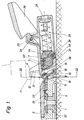
- FIG. 1 shows a heel area of the plate binding in a longitudinal section
- FIG. 2 shows the same area in plan view
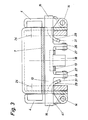
- FIG. 3 shows a section across the binding in the area of the sole hold-down device
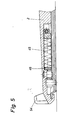
- FIGS. 4 and 5 show a possible configuration of the cheek area Binding.
- the binding essentially consists of a base plate 37 fastened to the ski 5, which, in a rotationally secured manner, receives a vertical axis 1 designed as a molded bolt, a plate 2 rotatably mounted on this vertical axis and a heel holder which is fixedly connected to the plate 2 and which has a step plate which can be pivoted about an axis 25 7 has.
- the tread plate 7 carries sole hold-downs 4 on both sides, which are designed as grippers, and hold the shoe 11 in the direction of travel at a point 13 of the same configuration as the opening of the grippers 12, both frontally and laterally.
- the tread plate 7 has a downwardly projecting control cam 32 which is acted upon by a control cam 33 which is fixedly connected to the release lever 36.
- the control cam 33 is pivoted on a pivot axis 38 in the heel holder 3.
- the side opposite the control cam is acted upon by a piston 34 which is supported against the force of a spring 35.
- the spring 35 is in the housing of the heel holder 3 as in conventional heel holders housed and has a bias adjuster 39 which is supported against the housing. If the trigger lever 36 is now pressed down, the control cam 33, which is rigidly connected to the trigger lever 36, pivots upward and thus engages under the underside of the step plate 7. Due to the control cam 32, the control cam 33 is about its axis 38 against the Piston 34 pressed, which further compresses the spring 35.
- the cam 33 has a control surface 40 which is the same as the control cam 32 and on which the control cam 32 now slides upwards until it disengages from the control cam 33, causing the sole holder to snap and the ski boot 11 to be released.
- the control cam 32 pulls up with the tread plate 7, since the sole hold-down devices 4 are pulled by the shoe 11 to the same snap-off point.
- the process of a torsion release is caused by a rotation of the plate 2 about the vertical axis 1.
- a control part 9, which is mounted in the plate 2 and held in a basic position by a spring 22, is pulled in the direction of travel of the ski, since the control part 9 engages with a hook 22 on an engagement part which is fixedly connected to the vertical axis 1.
- the control part 9 is hook-shaped.
- the hook 19 points upwards and engages behind a locking device 10, which prevents the sole hold-down device 4 from pivoting in a manner not initially shown.
- the locking device 10 has further downwardly projecting tines 26 which are pivotably articulated on a part 27 fixed to the tread plate by means of a bearing pin 15 (see FIG. 3).
- the locking device is tensioned by means of a spring 8 against the direction of travel.
- the control part 9 is thus pulled with its hook 19 in the direction of travel, as a result of which the locking means 10 about the axis 15 is also pulled in the direction of travel against the force of the spring 8.
- the locking device 10 comes from the points not shown Sole hold-down devices 4 out of engagement, which in turn fold them open laterally in accordance with the torsional moment and release the ski boot 11.
- the hook 19 of the control part 9 advantageously has a recess into which a prong 18 of the locking device engages.
- This tine is cranked against the direction of travel, a radius being provided for this crank, which has its center 24 in the axis 25 of the tread plate 7.
- the cranked prong 18 also ensures a vertical elasticity when the binding is subjected to torsional stress, since the prong 18 slides along the hook 19 and this therefore continues to act on the locking device 10.
- the locking device 10 has clip-shaped ends 16 which laterally enclose the sole hold-down devices 4 and thus prevent it from swinging open.
- the sole hold-down devices 4 are mounted on axles 14 which extend in the longitudinal direction of the ski and are fastened to the tread plate. Leg springs 41 press the sole hold-down devices 4 in the direction of the tread plate.
- the control part 9 engages with hooks 22 entrainment parts 21 which are arranged on a flange attachment 42 which is fixedly connected to the vertical axis 1.
- the control part 9 is mounted in the plate 2 and is therefore pulled by the driving parts 21 in the direction of travel when the latter is pivoted about the vertical axis 1.
- the hook 19 of the control part 9 also pulls the locking device 10 in the direction of travel until the clip ends 16 come out of engagement with the sole hold-down devices 4, or with opposite receiving points 17 thereof. If the locking device is disengaged, the sole hold-down devices 4 can swing out laterally against the force of the leg springs 41.
- FIG. 1 As can be seen from FIG.
- the sole hold-down devices have sliding projections 29 which are connected in one piece and each have a projection 31.
- the function of these sliding extensions 29 is based on the fact that they come into engagement with the clip ends 16 after the sole holding-down parts 4 have been pivoted out, as a result of which these clip ends 16 can slide on the sliding extensions 29 up to the projection 21.
- the projection 31 prevents another Swiveling out the sole hold-down device 4.
- the sliding of the clamp ends 16 on the sliding extensions 29 prevents the locking device 10 from snapping back in a non-operationally safe manner at a point in time at which the torsional forces which have led to the rotation release have already dropped again.
- a further spring 45 is supported, which is pressed by a piston 46 against a spring abutment 47.
- the spring abutment 47 has a conical surface 48 which projects from the spring and which is supported against the plate 2 by means of a double cone.
- the double cone has a thread in the middle with an adjusting screw 49. If the adjusting screw 49 is turned, the double cone moves in the axial direction of the screw, as a result of which the preload of the spring 45 can be changed.
- the piston 46 is acted upon by a control cam 51 pivotably mounted about an axis 50.
- the control cam 51 has on its end facing away from the piston 46 a link 52 which, due to the force of the spring 45, is pressed against a control pin fixed to the base plate.
- the shape of the backdrop 52 is approximately V-shaped, the tip of the V-s pointing against the direction of travel.
- the link 52 is now displaced along the control bolt 53, whereby it pivots about the axis 50 and thereby displaces the piston 46 against the ski direction, as a result of which the spring 45 is further compressed.
- the front sole retainer 54 is integrally and immovably connected to the plate 2.
- the horizontal release takes place through the force transmission of the shoe 11 to the sole hold-down device 4 or 54, whereby the plate 2 is rotated against the force of the spring 45.
- the control part 9, which engages at least one ski-fixed driving part 21 is pulled in the direction of travel, its hook 19 disengaging the locking device 10, which fixes the sole hold-down device 4, and thereby releases the ski shoe sole.
Landscapes
- Footwear And Its Accessory, Manufacturing Method And Apparatuses (AREA)
Applications Claiming Priority (2)
| Application Number | Priority Date | Filing Date | Title |
|---|---|---|---|
| AT0138384A AT381032B (de) | 1984-04-26 | 1984-04-26 | Skibindung |
| AT1383/84 | 1984-04-26 |
Publications (3)
| Publication Number | Publication Date |
|---|---|
| EP0159672A2 true EP0159672A2 (fr) | 1985-10-30 |
| EP0159672A3 EP0159672A3 (en) | 1987-09-09 |
| EP0159672B1 EP0159672B1 (fr) | 1991-09-11 |
Family
ID=3512691
Family Applications (1)
| Application Number | Title | Priority Date | Filing Date |
|---|---|---|---|
| EP85104728A Expired - Lifetime EP0159672B1 (fr) | 1984-04-26 | 1985-04-18 | Fixation de ski |
Country Status (4)
| Country | Link |
|---|---|
| US (1) | US4647065A (fr) |
| EP (1) | EP0159672B1 (fr) |
| AT (1) | AT381032B (fr) |
| DE (1) | DE3584028D1 (fr) |
Families Citing this family (2)
| Publication number | Priority date | Publication date | Assignee | Title |
|---|---|---|---|---|
| FR2643566B1 (fr) * | 1989-02-27 | 1991-01-11 | Rossignol Sa | Fixation de ski de securite |
| US6722688B2 (en) | 2001-11-21 | 2004-04-20 | The Burton Corporation | Snowboard binding system |
Family Cites Families (12)
| Publication number | Priority date | Publication date | Assignee | Title |
|---|---|---|---|---|
| US3740064A (en) * | 1971-05-06 | 1973-06-19 | S Weg | Ski binding |
| CH617861A5 (fr) * | 1975-12-31 | 1980-06-30 | Bernhard Kirsch | |
| AT352599B (de) * | 1977-02-23 | 1979-09-25 | Tyrolia Freizeitgeraete | Sicherheitsskibindung |
| FR2397851A1 (fr) * | 1977-07-22 | 1979-02-16 | Garcia Corp | Fixation de securite pour ski |
| US4182524A (en) * | 1977-08-26 | 1980-01-08 | Look S.A. | Safety ski binding |
| DE2804986C2 (de) * | 1978-02-06 | 1986-10-02 | Marker, Hannes, 8100 Garmisch-Partenkirchen | Sicherheits-Skibindung |
| DE2825876A1 (de) * | 1978-06-13 | 1980-01-03 | Gertsch Ernst | Sicherheitsskibindung |
| CH627945A5 (en) * | 1978-06-27 | 1982-02-15 | Suhner Intertrade Ag | Ski binding having a support which can be rotated about a vertical axis |
| FR2494591B1 (fr) * | 1980-11-27 | 1985-06-28 | Salomon & Fils F | Fixation de securite pour ski |
| AT372871B (de) * | 1981-12-18 | 1983-11-25 | Tyrolia Freizeitgeraete | Sicherheitsskibindung |
| AT374695B (de) * | 1982-08-12 | 1984-05-25 | Tyrolia Freizeitgeraete | Sicherheitsskibindung |
| AT377185B (de) * | 1982-11-24 | 1985-02-25 | Tyrolia Freizeitgeraete | Sicherheitsskibindung |
-
1984
- 1984-04-26 AT AT0138384A patent/AT381032B/de not_active IP Right Cessation
-
1985
- 1985-04-18 DE DE8585104728T patent/DE3584028D1/de not_active Expired - Lifetime
- 1985-04-18 EP EP85104728A patent/EP0159672B1/fr not_active Expired - Lifetime
- 1985-04-26 US US06/727,505 patent/US4647065A/en not_active Expired - Fee Related
Also Published As
| Publication number | Publication date |
|---|---|
| EP0159672B1 (fr) | 1991-09-11 |
| EP0159672A3 (en) | 1987-09-09 |
| AT381032B (de) | 1986-08-11 |
| US4647065A (en) | 1987-03-03 |
| ATA138384A (de) | 1986-01-15 |
| DE3584028D1 (de) | 1991-10-17 |
Similar Documents
| Publication | Publication Date | Title |
|---|---|---|
| DE2023169C2 (de) | Sicherheitsskibindung | |
| DE2502956C2 (de) | Sohlenniederhalter für eine Ski-Sicherheitsbindung | |
| DE3310739C2 (fr) | ||
| DE2756897A1 (de) | Sicherheitsskibindung | |
| EP0152629A2 (fr) | Fixation de ski | |
| DE3143576C2 (de) | Backen, insbesondere Vorderbacken, für Sicherheitsskibindungen | |
| DE2907365C2 (de) | Langlauf-Sicherheitsskibindung | |
| CH646340A5 (de) | Sicherheitsskibindung. | |
| EP0394380B1 (fr) | Fixation de securite pour ski | |
| DE2600858C3 (de) | Skisicherheitsbindung mit einer mit dem Schuh lösbar verbundenen Trittplatte | |
| EP0272317B1 (fr) | Fixation de securite pour ski | |
| DE2658999C2 (de) | Auslöseskibindung | |
| DE2804986C2 (de) | Sicherheits-Skibindung | |
| DE3227232C2 (de) | Fersenhalterung für eine Langlaufskibindung | |
| DE3326451C2 (de) | Bremsvorrichtung für ein Wintersportgerät | |
| EP0271693A2 (fr) | Mâchoire avant pour fixations de sécurité de ski | |
| DE3245668C2 (de) | Auslösende Langlaufbindung | |
| EP0159672B1 (fr) | Fixation de ski | |
| EP0254829B1 (fr) | Fixation de sécurité pour ski | |
| EP0157091B1 (fr) | Soutien de talon | |
| DE1428961C (de) | Auslosende Skibindung fur den Abfahrts lauf | |
| DE1478209C3 (fr) | ||
| EP4574222A1 (fr) | Talonniere pour une fixation de planche de glisse et planche de glisse | |
| DE3718455C2 (fr) | ||
| EP0947225B1 (fr) | Fixation de sécurité de ski |
Legal Events
| Date | Code | Title | Description |
|---|---|---|---|
| PUAI | Public reference made under article 153(3) epc to a published international application that has entered the european phase |
Free format text: ORIGINAL CODE: 0009012 |
|
| AK | Designated contracting states |
Designated state(s): CH DE FR LI |
|
| PUAL | Search report despatched |
Free format text: ORIGINAL CODE: 0009013 |
|
| AK | Designated contracting states |
Kind code of ref document: A3 Designated state(s): CH DE FR LI |
|
| 17P | Request for examination filed |
Effective date: 19880123 |
|
| 17Q | First examination report despatched |
Effective date: 19890412 |
|
| GRAA | (expected) grant |
Free format text: ORIGINAL CODE: 0009210 |
|
| AK | Designated contracting states |
Kind code of ref document: B1 Designated state(s): CH DE FR LI |
|
| REF | Corresponds to: |
Ref document number: 3584028 Country of ref document: DE Date of ref document: 19911017 |
|
| ET | Fr: translation filed | ||
| RAP2 | Party data changed (patent owner data changed or rights of a patent transferred) |
Owner name: TMC CORPORATION |
|
| PLBE | No opposition filed within time limit |
Free format text: ORIGINAL CODE: 0009261 |
|
| STAA | Information on the status of an ep patent application or granted ep patent |
Free format text: STATUS: NO OPPOSITION FILED WITHIN TIME LIMIT |
|
| 26N | No opposition filed | ||
| REG | Reference to a national code |
Ref country code: CH Ref legal event code: PUE Owner name: HTM SPORT- UND FREIZEITGERAETE GMBH |
|
| REG | Reference to a national code |
Ref country code: FR Ref legal event code: TP |
|
| REG | Reference to a national code |
Ref country code: CH Ref legal event code: PFA Free format text: HTM SPORT- UND FREIZEITGERAETE AKTIENGESELLSCHAFT |
|
| PGFP | Annual fee paid to national office [announced via postgrant information from national office to epo] |
Ref country code: DE Payment date: 19940423 Year of fee payment: 10 |
|
| PGFP | Annual fee paid to national office [announced via postgrant information from national office to epo] |
Ref country code: FR Payment date: 19940427 Year of fee payment: 10 |
|
| PGFP | Annual fee paid to national office [announced via postgrant information from national office to epo] |
Ref country code: CH Payment date: 19940502 Year of fee payment: 10 |
|
| REG | Reference to a national code |
Ref country code: FR Ref legal event code: TP |
|
| PG25 | Lapsed in a contracting state [announced via postgrant information from national office to epo] |
Ref country code: LI Effective date: 19950430 Ref country code: CH Effective date: 19950430 |
|
| REG | Reference to a national code |
Ref country code: CH Ref legal event code: PL |
|
| PG25 | Lapsed in a contracting state [announced via postgrant information from national office to epo] |
Ref country code: FR Effective date: 19951229 |
|
| PG25 | Lapsed in a contracting state [announced via postgrant information from national office to epo] |
Ref country code: DE Effective date: 19960103 |
|
| REG | Reference to a national code |
Ref country code: FR Ref legal event code: ST |