EP0160137A1 - Milieu d'enregistrement avec couche d'enregistrement à épaisseur variable - Google Patents
Milieu d'enregistrement avec couche d'enregistrement à épaisseur variable Download PDFInfo
- Publication number
- EP0160137A1 EP0160137A1 EP84302897A EP84302897A EP0160137A1 EP 0160137 A1 EP0160137 A1 EP 0160137A1 EP 84302897 A EP84302897 A EP 84302897A EP 84302897 A EP84302897 A EP 84302897A EP 0160137 A1 EP0160137 A1 EP 0160137A1
- Authority
- EP
- European Patent Office
- Prior art keywords
- disk
- recording layer
- recording
- layer
- area
- Prior art date
- Legal status (The legal status is an assumption and is not a legal conclusion. Google has not performed a legal analysis and makes no representation as to the accuracy of the status listed.)
- Withdrawn
Links
- 229910052751 metal Inorganic materials 0.000 claims abstract description 23
- 239000002184 metal Substances 0.000 claims abstract description 20
- 239000000758 substrate Substances 0.000 claims description 40
- 238000000151 deposition Methods 0.000 claims description 24
- 229910017052 cobalt Inorganic materials 0.000 claims description 19
- 239000010941 cobalt Substances 0.000 claims description 19
- GUTLYIVDDKVIGB-UHFFFAOYSA-N cobalt atom Chemical compound [Co] GUTLYIVDDKVIGB-UHFFFAOYSA-N 0.000 claims description 19
- 239000010405 anode material Substances 0.000 claims description 9
- 238000000034 method Methods 0.000 claims description 9
- 230000004888 barrier function Effects 0.000 claims description 7
- 230000007423 decrease Effects 0.000 claims description 2
- 238000010276 construction Methods 0.000 abstract 1
- 239000010410 layer Substances 0.000 description 169
- 239000000463 material Substances 0.000 description 10
- 229910052782 aluminium Inorganic materials 0.000 description 9
- XAGFODPZIPBFFR-UHFFFAOYSA-N aluminium Chemical compound [Al] XAGFODPZIPBFFR-UHFFFAOYSA-N 0.000 description 9
- HCHKCACWOHOZIP-UHFFFAOYSA-N Zinc Chemical compound [Zn] HCHKCACWOHOZIP-UHFFFAOYSA-N 0.000 description 5
- 239000010408 film Substances 0.000 description 5
- 229910052725 zinc Inorganic materials 0.000 description 5
- 239000011701 zinc Substances 0.000 description 5
- 238000005516 engineering process Methods 0.000 description 3
- 238000004519 manufacturing process Methods 0.000 description 3
- 239000000203 mixture Substances 0.000 description 3
- PXHVJJICTQNCMI-UHFFFAOYSA-N Nickel Chemical compound [Ni] PXHVJJICTQNCMI-UHFFFAOYSA-N 0.000 description 2
- 229910045601 alloy Inorganic materials 0.000 description 2
- 239000000956 alloy Substances 0.000 description 2
- 238000013459 approach Methods 0.000 description 2
- 239000011248 coating agent Substances 0.000 description 2
- 238000000576 coating method Methods 0.000 description 2
- 238000009826 distribution Methods 0.000 description 2
- 230000001939 inductive effect Effects 0.000 description 2
- 230000000977 initiatory effect Effects 0.000 description 2
- 150000002739 metals Chemical class 0.000 description 2
- 238000012856 packing Methods 0.000 description 2
- 238000007747 plating Methods 0.000 description 2
- 239000011253 protective coating Substances 0.000 description 2
- 229910001096 P alloy Inorganic materials 0.000 description 1
- 230000015572 biosynthetic process Effects 0.000 description 1
- 238000004880 explosion Methods 0.000 description 1
- 239000007769 metal material Substances 0.000 description 1
- 229910052759 nickel Inorganic materials 0.000 description 1
- SIBIBHIFKSKVRR-UHFFFAOYSA-N phosphanylidynecobalt Chemical compound [Co]#P SIBIBHIFKSKVRR-UHFFFAOYSA-N 0.000 description 1
- 239000011241 protective layer Substances 0.000 description 1
- 238000003860 storage Methods 0.000 description 1
- 239000010409 thin film Substances 0.000 description 1
Images

Classifications
-
- G—PHYSICS
- G11—INFORMATION STORAGE
- G11B—INFORMATION STORAGE BASED ON RELATIVE MOVEMENT BETWEEN RECORD CARRIER AND TRANSDUCER
- G11B5/00—Recording by magnetisation or demagnetisation of a record carrier; Reproducing by magnetic means; Record carriers therefor
- G11B5/62—Record carriers characterised by the selection of the material
- G11B5/64—Record carriers characterised by the selection of the material comprising only the magnetic material without bonding agent
- G11B5/65—Record carriers characterised by the selection of the material comprising only the magnetic material without bonding agent characterised by its composition
- G11B5/656—Record carriers characterised by the selection of the material comprising only the magnetic material without bonding agent characterised by its composition containing Co
-
- G—PHYSICS
- G11—INFORMATION STORAGE
- G11B—INFORMATION STORAGE BASED ON RELATIVE MOVEMENT BETWEEN RECORD CARRIER AND TRANSDUCER
- G11B5/00—Recording by magnetisation or demagnetisation of a record carrier; Reproducing by magnetic means; Record carriers therefor
- G11B5/62—Record carriers characterised by the selection of the material
- G11B5/73—Base layers, i.e. all non-magnetic layers lying under a lowermost magnetic recording layer, e.g. including any non-magnetic layer in between a first magnetic recording layer and either an underlying substrate or a soft magnetic underlayer
- G11B5/7368—Non-polymeric layer under the lowermost magnetic recording layer
-
- G—PHYSICS
- G11—INFORMATION STORAGE
- G11B—INFORMATION STORAGE BASED ON RELATIVE MOVEMENT BETWEEN RECORD CARRIER AND TRANSDUCER
- G11B5/00—Recording by magnetisation or demagnetisation of a record carrier; Reproducing by magnetic means; Record carriers therefor
- G11B5/74—Record carriers characterised by the form, e.g. sheet shaped to wrap around a drum
- G11B5/82—Disk carriers
-
- G—PHYSICS
- G11—INFORMATION STORAGE
- G11B—INFORMATION STORAGE BASED ON RELATIVE MOVEMENT BETWEEN RECORD CARRIER AND TRANSDUCER
- G11B5/00—Recording by magnetisation or demagnetisation of a record carrier; Reproducing by magnetic means; Record carriers therefor
- G11B5/84—Processes or apparatus specially adapted for manufacturing record carriers
- G11B5/858—Producing a magnetic layer by electro-plating or electroless plating
Definitions
- This invention relates to a magnetic recording disk and to a process of preparing the same.
- disks containing magnetic recording layers are routinely used. Recent advances in the technology associated with the use of these disks has resulted in achieving higher and higher bit densities on smaller disks. Routinely, presently, five inch (12.7cm) disks now are utilized where 14 inch (35.6cm) disks were used in the past. The use of these smaller diameter disks are the direct result of achieving increases in the bit density on the recording layers of the disks.
- the recording disks are spun under a transducer or recording head.
- Present technology allows the placement of the recording head at a flight height approaching zero with respect to the uppermost layer of the disk. Because the flight height of the recording head does approach contact with the surface of the recording disk recording disks prepared such as those in U.S. Patent 4,224,381 are used to prevent catastrophic loss of the recorded media on that disk when contact is made between the recording head and the upper surface of the disk.
- the data which is recorded on the recording layer of a disk is located in tracks which extend outwardly from the center or hub area of the disk toward the outside periphery of the disk. Because the disk is round and because the center of rotation of the disk is at the center of the disk the velocity of the disk movement underneath the recording head is less at the inner tracks which have a smaller radius from the center of the disk than it is with respect to the outer tracks which are at a larger radius from the center of the disk. Additionally, the track length at the inner tracks is much smaller than the track length at the outer tracks. Because the track length at the inner tracks is less than the track length at the outer tracks there is a higher bit packing density at the inner tracks with respect to the outer tracks. Because the bit density is higher at the inner tracks the output at the inner tracks is different from the output at the outer tracks.
- a magnetic recording disk which comprises a substrate having a disk central hub area, a circumferential rim area and an intermediate area located between said hub area and said rim area, at least one non-recording layer located over said substrate disk and overlaying said hub area, said intermediate area and said rim area, a magnetic recording layer located over said non-recording layer, and having an inner track zone overlaying said hub area, an intermediate track zone overlaying said intermediate area and an outer track zone overlaying said rim area, characterised in that the thickness of said recording layer at its inner track zone is less than the thickness of said recording layer at its intermediate track zone.
- a process of preparing a magnetic recording disk comprising electrolessly depositing upon a disk shaped substrate a metal-containing non-recording support layer, contacting said support layer with an anodic metal which is more electro-positive than cobalt, said contact being at an area proximal to that area which will underlay the inner track zone of said recording disk and said contact with said anodic material producing an area of positive charge at said area of said support layer which will underlay said inner track zone, electrolessly depositing upon said support layer a cobalt-containing recording layer, the thickness of said cobalt-containing recording layer at said area of positive charge being less than the thickness of said cobalt-containing recording layer overlaying the remainder of said support layer.
- the embodiments of the invention to be described herein provide a magnetic recording disk which approaches consistent output between the inner zone tracks and the outer zone tracks. Also a higher coercivity is achieved at the inner zone tracks with respect to those zone tracks which are radially displaced outwardly from the inner zone tracks, in view of the higher bit packing density at the inner zone. Further, the recording disks are economically produced and can thus be made economically available to the consumer.
- the magnetic recording disks of the invention in addition to having the recording layer being thinner near the inner track zone, can also include other layers located beneath or above the recording layer with respect to the substrate of the disk. As such, magnetic layers and shield layers can be located between the substrate disk and the recording layer and- further barrier layers and protecting layers can be located over the recording layer.
- the thickness of the recording layer at the outer track zone can be made thinner with respect to the thickness of the recording layer at intermediate track zone in order to improve output characteristics in large diameter disks wherein the radius of the outer track zone is substantially greater than the radius at the inner track zone.
- the film thickness of the magnetic recording layer at the inner track zone would be from about 5% to about 20% less than the film thickness of the recording layer at intermediate track zones.
- a more preferred range for the thickness of the recording layer at the inner track zone would be from about 10% to about 15% less than the thickness of the recording layer at intermediate track zones.
- electroless depositing of the individual layers upon a disk substrate is performed. After electrolessly depositing any non-recording layers which will underlie the recording layer the layer immediately underlying the recording layer is then contacted with an anodic material at the area wherein it is desirable that the recording layer be deposited thinner than in other areas.
- the material chosen for the anode is selected to be a more electro- positive metal than metallic elements in the recording layer. In the preferred embodiment wherein cobalt is utilized for the metallic element in the recording layer the material selected for the anode would thus be a material which is more electro-positive than cobalt.
- aluminum and zinc are chosen as the anodic material.
- the disk substrate itself can be utilized as this anode.
- an opening can be formed in all layers lying between the disk substrate and the recording layer prior to electrolessly depositing the recording layer thereon to expose the disk substrate preferably aluminum, and induce a positive charge at the area of exposure of the disk substrate.
- the partially prepared recording disk can be contacted with an anodic material at the area corresponding to both the inner zone tracks and the outer zone tracks.
- anodic material at the area corresponding to both the inner zone tracks and the outer zone tracks.
- the present invention is directed to a magnetic recording disk wherein the thickness of the recording layer is reduced at specific zones compared to other zones so as to normalize the output of all of the zones.
- Fig. 1 shows a typical magnetic recording disk 10.
- the disk contains a center cutout hole 12 allowing for appropriately mounting of the finished disk upon a spindle (not shown or numbered) for use in storing and retreaving data onto and from the magnetic recording disk 10.
- a recording head (also not shown or numbered) is utilized in conjunction with the disk 10 with the recording head serving as the input and output of signals to the disk 10 for the transfer of information between the disk 10 and a suitable electronic appliance such as a computer or the like.
- the particular tracks wherein the magnetic information is stored can be divided into an inner track zone 14, an intermediate track zone 16 and an outer track zone 18.
- the exact radial dimensions from the center of the magnetic recording disk 10 of these particular zones 14, 16 and 18, of course, would depend upon the dimensions of the magnetic recording disk 10 itself. Disk size range anywhere from three inches minimum to approximately three feet maximum. More commonly, however, the disk would range from about five inches to fourteen inches.
- dotted lines 20 and 22 generally delineate the inner track zone 14 with the dotted lines 22 and 24 generally delineating the intermediate track zone 16 and the dotted line 24 and the periphery of the disk 26 generally delineating the outer track zone 18.
- a cut-out hole such as cut-out hole 12 may or may not be present.
- other locating holes may be located near the center of the magnetic recording disk 10 as would be appropriate for the particular disk drives which would be utilized to rotate the particular disk.
- the magnetic recording disk 10 can be divided into these three zones 14, 16 and 18 as delineated above.
- the magnetic recording disk 10 shown in Fig. 1 is shown in a sectional side elevational view, however, the view has been modified with respect to the ratio of the vertical thickness with respect to the horizontal diameter of the magnetic recording disk 10.
- the thickness of the magnetic recording disk 10 that is the vertical dimension, has been grossly exaggeratedwith respect to the diameter of the magnetic recording disk 10 that is the horizontal direction.
- the magnetic recording disk 10 may be measured in inches with respect to its diameter the thickness of the individual layers grossly exaggerated in Fig. 2 would be on the order of micro-inches.
- a typical disk utilizing the principles of this invention can be constructed as follows.
- a substrate 28 forms the foundation for the magnetic recording disk 10. Overlayed on the substrate 28 is a magnetic layer 30. Overlayed on the magnetic layer 30 is a shield layer 32. Overlayed on the shield layer 32 is a recording layer 34. Overlayed on the recording layer 34 is a barrier layer 36. And overlayed on the barrier layer 36 is an outermost layer of the magnetic recording disklO, being a protective coating.38.
- the substrate 28, magnetic layer 30, shield layer 32 and recording layer 34 would be formed essentially as is described in U.S. Patent 4,224,381.
- the barrier layer 36 and . the protective coating 38 reference is made to U.S. Patent 4,124,736.
- the particular layers 30, 32,34, 36 and 38 would be formed preferably by electroless depositing techniques as are outlined in U.S. Patent 4,224,381 and 4;124,736
- the particular compositions of the individual layers would be also as outlined in these two referred to patents.
- the recording layer 34 would not be formed as a layer having a uniform thickness across the entire surface of the magnetic recording disk 10. Instead the thickness of the recording layer 34 would be varied such that at certain zones as hereinafter described the thickness of the recording layer 34 would be thinner than the thickness of the recording layer 34 at-other zones.
- cobalt is considered to be the preferred material constituting the composition forming the recording layer 34.
- the thickness of the recording layer would be on the order of several micro-inches as for instance two micro-inches. Thicker recording layers, however, also could be utilized with the thickness of the recording layer adjusted with regard to the frequency of the signal of the recording head.
- the magnetic layer 30 would be pure cobalt, however cobalt alloyed with amounts of nickel or other elements compatable with cobalt for use in recording layers could also be utilized.
- U.S. Patent 3,719,525 there is described the use of a cobalt phosphorus alloy for a recording layer. Other alloys are also known in the art for the preparaton of suitable recording layers.In any event preferably the cobalt based recording layer would be appropriately electrolessly deposited upon subsequent underlying layers such as the shield layer 32 of Fig. 2.
- the substrate 28 For the purposes of preparing the magnetic recording disk 10 preferably aluminum is chosen for the substrate 28.
- the aluminum substrate 28 can be overcoated with a zinc coating as per tie teachings of U.S. Patent 4,224,381 for the desirable properties resulting from such a zinc overcoating or the substrate 28 can be utilized without such an appropriate coating.
- the substrate 28 is a more electro-positive metal than the metal forming the recording layer 34 the desired differential in the thickness of the recording layer 34 of this invention can be achieved utilizing the substrate 28 as an anode to induce an electrical charge onto particular zone areas of the partially formed magnetic recording disk 10.
- any layer which overlays the recording layer 34 such as the barrier layer 36 or the protective layer 38 should be of such a non-magnetic character that it does not influence the magnetic character of the recording layer 34.
- Typical of such overlaying layers would be those as described in U.S. Patent 4,124,736.
- those layers which overlay the recording layer 34 preferably would be formed by electroless depositing of the same upon the recording layer 34.
- the thickness of the recording layer 34 at the inner track zone 14 which is located adjacent to the central hub area or the cut-out hole 12 of the magnetic recording disk 10 is less than the thickness of the recording layer 34 radially displaced outwardly at the intermediate track zone 16.
- the reduction in the thickness in the recording layer 34 at the inner track zone 14 compensates for the increase in bit density at the inner track zone 14 resulting from the lower velocity of the inner track zone 14 compared to zones radially displaced outwardly from it upon rotation of the magnetic recording disk 10.
- This increase the output at the inner track zone 14 to compensate for the increase of bit density resulting from the circular geometry of the magnetic recording disk 10. Because the recording layer 34 is thinner at the inner track zone 10 its coercivity is higher at these zones resulting in better performance of the magnetic recording disk 10.
- the decrease of thickness of the recording layer 34 at the inner track zones as well as other zones as hereinafter explained can be achieved by contacting the partially formed magnetic recording disk 10 just prior to or during the electroless depositing of the recording layer 34 thereon.
- the partially formed magnetic recording disk 10 such as a partially formed magnetic recording disk 10 having both a magnetic layer 30 and a shield layer 32 already deposited thereon
- a metallic material which is more electro-positive than the outermost layer on the partially formed magnetic recording disk 10 a positive charge is created at the area of contact.
- a partially formed disk 40 is mounted upon a mandrel 42 such that contact is made between the mandrel 42 and the surface of the barrier layer 36 which is located at the cut-out hole 12.
- the mandrel 42 is chosen such that it is a metal which is more electro-positive than the material which will comprise the recording layer 34.
- suitable materials for the mandrel 42 would be aluminum, zinc or other such anodic metals which are higher up (located -oward the anodic end) in the electromotive series of metals and alloys.
- a positive electrical charge such as that depicted by the numeral 44 in Fig. 3 is distributed in the immediate vicinity of the con act between the mandrel 42 and the partially formed disk 40.
- the presence of the positive charge 44 at the area which will underlie the inner track zone 14 suppresses the initial depositing of the recording layer 34 at this area.
- An initial deposit of material which will form the recording layer 34 starts in those areas wherein the positive charge 44 is not located such as the intermediate track zone 16 and the outer track zone 18.
- the positive charge 44 is overcome and material starts to deposit at this area also.
- the recording layer 34 which is deposited at the inner track zone 14, since its depositing was suppressed, ultimately is thinner than those areas wherein depositing of the material forming the recording layer 34 occurred for a longer period of time. This results in a somewhat concave upper surface for the recording layer 34 wherein the radius of curvature of this concave upper surface is measured in angstroms. While the actual differences in the thickness of the recording layer 34 at zones 14 and 16 is small it is, however, sufficient to compensate for the increase bit density which will occur at the inner tracK zone 14.
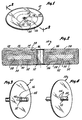
- both the inner track zone 14 and the outer track zone 18 of a reduced thickness compared to the intermediate track zone 16 and as such as seen - n Fig. 6 a positive charge can be induced at both the inner track zone 14 and the outer track zone 18. In this case plating is retarded at both of these areas with respect to the intermediate track zone 16 resulting in the formation of a recording layer 34 which has a reduced thickness at both the inner track zone 14 and the outer track zone 18.
- Fig. 7 such a disk is shown.
- the partially formed disk 46 has a recording layer 48 located thereon which has a reduced thickness at both the inner track zone 14 and the outer track zone 18.
- the output is improved compared to conventionally prepared recording disks now known.
- the output would be at about 1.5 millivolts.
- the output is normalized to where it only varies approximately 30%. This is compared to the almost 95% variance presently achieved utilizing conventional production techniques for currently available magnetic recording disks.
- the thickness of the recording layer 34 between the inner track zone 14 and the intermediate track zone 16 is only necessary to vary the thickness of the recording layer 34 between the inner track zone 14 and the intermediate track zone 16 from about 5% to 20%. Preferably, however, the difference between the thicknesses of these two zones would be from about 10% to about 15%. As was noted previously current recording technology requires that the recording layer 34 be of a very small dimension in the order of several micro-inches. This difference between the thicknesses of the inner track zone 14 and the intermediate track zone 16 can easily be achieved by the utilzation of the above noted contact with an anodic metal to create an area of positive charge on the partially formed disk prior t J the depositing of the recording layer thereon.
- Figs. 4 and 5 show two alternate possible ways of introducing this positive charge onto the partially formed disk.
- the partially formed disk 50 is shown suspended on a triangular formed mandrel 52.
- the mandrel 52 contacts the partially formed disk 50 at three points of contact instead of in a continous contact as is seen in Fig. 3.
- an area of positive charge 54 is induced onto the partially formed disk 52 such that during depositing of a recording layer thereon initiation of depositing at the area of positive charge 54 is retarded with respect to initiation of depositing of the recording layer at the other areas not so positively charged.
- Fig. 5 an alternate way of inducing a positive charge onto a partially formed disk 56 is shown.
- the partially formed disk 56 has been overlayed with at least one layer such as a layer 58 which could be a shield layer, a combination magnetic layer or shield layer or the like equivalent to layers 30 and 32 previously discussed.
- a layer 58 which is metallic in nature is located on the partially formed disk 56.
- This layer 58 would have been overlayed onto a substrate such as an aluminum substrate as previously described.
- a small opening 66 is formed through the layer 58 to expose a portion of the substrate 62 through the opening 66.
- the substrate 62 With the exposure oi the substrate 62 an electronic couple can now be made between the substrate 62 and the outside surface of the layer 58 which induces a positive charge area 64 onto the layer 58 around the opening 66 of the disk 56.
- the substrate 62 is serving as the anodic metal to induce the positive charge 64.
- the partially formed disk 56 is introduced into a solution suitable for electroless depositing of a recording layer thereon the positive charge area 64 induced onto .the layer 58 by the electric couple passing through the opening 66 between the layer 58 and the substrate 62 retards initial depositing of the recording layer at the positive charge area 64.
- the use of the external mandrel or the like as the anodic metal to create the positive charge is not necessary.
- the substrate located inside of the partially formed disk 56 itself serves as this anodic metal. Since the substrate of the partially formed disk 56 is normally formed of aluminum or aluminum coated with zinc this substrate would be more electro-positive with respect to a typical recording layer such as a cobalt layer and the variability in the thickness of the .depositing of the recording layer upon the partially formed disk 56 would be achieved.
- an additional opening could also be located near the outer track zone of a partially formed disk to also induce a positive charge at those areas which underlay the outer track zone such that the recording layer deposited at the outer track zone would also be thinner than other portions of the recording layer such as the intermediate track zone.
Landscapes
- Magnetic Record Carriers (AREA)
- Manufacturing Of Magnetic Record Carriers (AREA)
Applications Claiming Priority (2)
| Application Number | Priority Date | Filing Date | Title |
|---|---|---|---|
| US06/489,370 US4522848A (en) | 1983-04-28 | 1983-04-28 | Process of preparing a recording member having a variable thickness recording layer |
| US489370 | 1984-04-28 |
Publications (1)
| Publication Number | Publication Date |
|---|---|
| EP0160137A1 true EP0160137A1 (fr) | 1985-11-06 |
Family
ID=23943582
Family Applications (1)
| Application Number | Title | Priority Date | Filing Date |
|---|---|---|---|
| EP84302897A Withdrawn EP0160137A1 (fr) | 1983-04-28 | 1984-04-30 | Milieu d'enregistrement avec couche d'enregistrement à épaisseur variable |
Country Status (3)
| Country | Link |
|---|---|
| US (1) | US4522848A (fr) |
| EP (1) | EP0160137A1 (fr) |
| JP (1) | JPS6040529A (fr) |
Families Citing this family (6)
| Publication number | Priority date | Publication date | Assignee | Title |
|---|---|---|---|---|
| US5108781A (en) * | 1990-03-12 | 1992-04-28 | Magnetic Peripherals Inc. | Process for manufacturing selectively textured magnetic recording media |
| US5062021A (en) * | 1990-03-12 | 1991-10-29 | Magnetic Peripherals Inc. | Selectively textured magnetic recording media |
| US6048255A (en) * | 1995-08-22 | 2000-04-11 | Seagate Technology, Inc. | Pulsed laser surface treatments for magnetic recording media |
| DE19651782C2 (de) * | 1996-12-12 | 1998-12-17 | Zinser Textilmaschinen Gmbh | Verfahren und Vorrichtung zur Herstellung eines Effektgarns |
| US6808783B1 (en) * | 2002-01-17 | 2004-10-26 | Maxtor Corporation | Storage media with non-uniform properties |
| US7592079B1 (en) | 2003-07-03 | 2009-09-22 | Seagate Technology Llc | Method to improve remanence-squareness-thickness-product and coercivity profiles in magnetic media |
Citations (5)
| Publication number | Priority date | Publication date | Assignee | Title |
|---|---|---|---|---|
| US4224381A (en) * | 1978-10-19 | 1980-09-23 | Poly Disc Systems, Inc. | Abrasion resistant magnetic record members |
| JPS5733436A (en) * | 1980-08-04 | 1982-02-23 | Yoshiro Nakamatsu | High-performance and flexible magnetic medium |
| JPS5774831A (en) * | 1981-08-31 | 1982-05-11 | Tdk Corp | Disk-like magnetic recording medium |
| JPS5862829A (ja) * | 1981-10-08 | 1983-04-14 | Nec Corp | 磁気記録体及びその製造方法 |
| JPS5885933A (ja) * | 1981-11-18 | 1983-05-23 | Mitsubishi Electric Corp | 磁気記録媒体 |
-
1983
- 1983-04-28 US US06/489,370 patent/US4522848A/en not_active Expired - Fee Related
-
1984
- 1984-04-28 JP JP59087649A patent/JPS6040529A/ja active Pending
- 1984-04-30 EP EP84302897A patent/EP0160137A1/fr not_active Withdrawn
Patent Citations (5)
| Publication number | Priority date | Publication date | Assignee | Title |
|---|---|---|---|---|
| US4224381A (en) * | 1978-10-19 | 1980-09-23 | Poly Disc Systems, Inc. | Abrasion resistant magnetic record members |
| JPS5733436A (en) * | 1980-08-04 | 1982-02-23 | Yoshiro Nakamatsu | High-performance and flexible magnetic medium |
| JPS5774831A (en) * | 1981-08-31 | 1982-05-11 | Tdk Corp | Disk-like magnetic recording medium |
| JPS5862829A (ja) * | 1981-10-08 | 1983-04-14 | Nec Corp | 磁気記録体及びその製造方法 |
| JPS5885933A (ja) * | 1981-11-18 | 1983-05-23 | Mitsubishi Electric Corp | 磁気記録媒体 |
Non-Patent Citations (5)
| Title |
|---|
| IBM TECHNICAL DISCLOSURE BULLETIN, vol. 24, no. 6, November 1981, New York, USA; A.M. HOMOLA et al. "Discrete magnetic tracks in storage disks", pages 2794-2795 * |
| Patent Abstracts of Japan vol. 6, no. 100, 9 June 1982 & JP-A-57-33436 * |
| Patent Abstracts of Japan vol. 6, no. 156, 17 August, 1982 & JP-A-57-74831 * |
| Patent Abstracts of Japan vol. 7, no. 152, 5 July 1983 & JP-A-58-62829 (Cat. A) * |
| Patent Abstracts of Japan vol. 7, no. 184, 13 August 1983 & JP-A-58-85933 (Cat. P, A) * |
Also Published As
| Publication number | Publication date |
|---|---|
| US4522848A (en) | 1985-06-11 |
| JPS6040529A (ja) | 1985-03-02 |
Similar Documents
| Publication | Publication Date | Title |
|---|---|---|
| US5285337A (en) | Liquid-bearing data recording disk file with transducer carrier having support struts | |
| US6338939B1 (en) | Embedded dual coil fabrication process | |
| US5241440A (en) | Thin film magnetic head and manufacturing method therefor | |
| KR0139308B1 (ko) | 기록 헤드의 평탄화 및 리드 라우팅을 동시에 하기 위한 방법 및 장치 | |
| EP0160137A1 (fr) | Milieu d'enregistrement avec couche d'enregistrement à épaisseur variable | |
| US20020176208A1 (en) | Slider deposits for control of pole-to-disc spacing | |
| CA1241741A (fr) | Contraste d'impedance dans un support d'enregistrement de donnees | |
| WO2003105134A1 (fr) | Depots sur patin destines a la regulation d'espacement pole-disque | |
| US8699184B2 (en) | Self-aligned bevels for write poles | |
| JPH117615A (ja) | 複合型磁気ヘッドの製造方法 | |
| US5879570A (en) | One piece flexure for a hard disc file head with selective nickel plating | |
| US6151194A (en) | Thin film inductive transducer with alumina gap positioned over coils | |
| US5687048A (en) | Magnetic disk cartridge and process for producing the same | |
| EP1998322B1 (fr) | Disque magnétique pour lecteurs de disque dur | |
| EP0125478B1 (fr) | Disque pour l'enregistrement magnétique avec une trace interne auxiliaire | |
| JPH0724097B2 (ja) | 垂直磁気記録媒体 | |
| JPS62219227A (ja) | 磁気記憶体 | |
| JPH0388114A (ja) | 磁気記録媒体 | |
| JPH0581662A (ja) | 垂直磁気記録媒体の製造方法 | |
| JPH06139541A (ja) | 磁気記録媒体 | |
| JPH0221414A (ja) | 薄膜磁気ヘッド | |
| JPH0233293Y2 (fr) | ||
| JPH06111267A (ja) | 磁気記録媒体 | |
| JPS63275012A (ja) | 薄膜磁気ヘツド | |
| JPH06111303A (ja) | 複数の磁気記憶ディスクを形成する方法および複数の磁気記憶ディスクを形成するためのブランク |
Legal Events
| Date | Code | Title | Description |
|---|---|---|---|
| PUAI | Public reference made under article 153(3) epc to a published international application that has entered the european phase |
Free format text: ORIGINAL CODE: 0009012 |
|
| AK | Designated contracting states |
Designated state(s): DE FR GB IT |
|
| STAA | Information on the status of an ep patent application or granted ep patent |
Free format text: STATUS: THE APPLICATION IS DEEMED TO BE WITHDRAWN |
|
| 18D | Application deemed to be withdrawn |
Effective date: 19860708 |
|
| RIN1 | Information on inventor provided before grant (corrected) |
Inventor name: PATEL, PRAVIN K. |