EP0367726A1 - Dispositif de compensation de l'affaissement de la broche de bobinage dans une machine à bobiner - Google Patents
Dispositif de compensation de l'affaissement de la broche de bobinage dans une machine à bobiner Download PDFInfo
- Publication number
- EP0367726A1 EP0367726A1 EP89810819A EP89810819A EP0367726A1 EP 0367726 A1 EP0367726 A1 EP 0367726A1 EP 89810819 A EP89810819 A EP 89810819A EP 89810819 A EP89810819 A EP 89810819A EP 0367726 A1 EP0367726 A1 EP 0367726A1
- Authority
- EP
- European Patent Office
- Prior art keywords
- roller
- pin
- winding
- mandrel
- bobbin
- Prior art date
- Legal status (The legal status is an assumption and is not a legal conclusion. Google has not performed a legal analysis and makes no representation as to the accuracy of the status listed.)
- Granted
Links
Images

Classifications
-
- B—PERFORMING OPERATIONS; TRANSPORTING
- B65—CONVEYING; PACKING; STORING; HANDLING THIN OR FILAMENTARY MATERIAL
- B65H—HANDLING THIN OR FILAMENTARY MATERIAL, e.g. SHEETS, WEBS, CABLES
- B65H54/00—Winding, coiling, or depositing filamentary material
- B65H54/02—Winding and traversing material on to reels, bobbins, tubes, or like package cores or formers
- B65H54/40—Arrangements for rotating packages
- B65H54/52—Drive contact pressure control, e.g. pressing arrangements
-
- B—PERFORMING OPERATIONS; TRANSPORTING
- B65—CONVEYING; PACKING; STORING; HANDLING THIN OR FILAMENTARY MATERIAL
- B65H—HANDLING THIN OR FILAMENTARY MATERIAL, e.g. SHEETS, WEBS, CABLES
- B65H2601/00—Problem to be solved or advantage achieved
- B65H2601/50—Diminishing, minimizing or reducing
- B65H2601/52—Diminishing, minimizing or reducing entities relating to handling machine
- B65H2601/524—Vibration
-
- B—PERFORMING OPERATIONS; TRANSPORTING
- B65—CONVEYING; PACKING; STORING; HANDLING THIN OR FILAMENTARY MATERIAL
- B65H—HANDLING THIN OR FILAMENTARY MATERIAL, e.g. SHEETS, WEBS, CABLES
- B65H2701/00—Handled material; Storage means
- B65H2701/30—Handled filamentary material
- B65H2701/31—Textiles threads or artificial strands of filaments
Definitions
- the present invention relates to a device for compensating the sag of the bobbin mandrel of a winder according to the preamble of patent claim 1.
- the spindles for receiving the spool are often mounted elastically in the machine frame.
- a tachometer or drive roller is arranged above the coil mandrel and can be pressed linearly on the surface of the coil. With increasing coil weight and consequently greater sag of the coil mandrel, the contact pressure of the tachometer roller is increasingly reduced towards the flying end.
- the object of the present invention is to provide a device which ensures a pivoting movement of the speedometer or drive roller.
- the device according to the invention makes it possible, in a cost-effective manner, to create a pivot bearing for the speedometer roller, which enables a pivoting movement both in both directions of rotation about the pivot axis and radially to the pivot axis.
- the O-rings which accommodate both the tangential and radial deflections of the yoke carrying the tachometer roller, allow the device to be operated completely maintenance-free for years.
- the characteristic of the adaptation of the tachometer roller to the inclination of the coil mandrel can be influenced by correspondingly varying the number and the preload of the O-rings.
- FIG. 1 shows an automatic winder 1 with two bobbins 5 mounted on a turret, a thread laying device 6 of known construction and the machine housing which contains the drive motors for the bobbin 5, the laying device 6 and the other units and parts of the control.
- the turret carrying the two spindles 5 is not shown and has a known construction.
- the two bobbin mandrels 5 are overhung, which means that empty tubes can be loaded or the full bobbins 3 can be removed by hand or by an automatic doffer.
- FIG. 2 only shows the winding mandrel 5 with two spools 3, the tachometer or drive roller 7 and the housing wall 9 facing the winding unit for the sake of clarity.
- the winding mandrel 5 is mounted in the housing of the winding machine 1 and connected to a drive.
- the end of the winding mandrel 5 facing away from the winding machine 1 is not supported. It is therefore a "flying" storage.
- the two coils 3 are placed on the spool mandrel 5 and held in a rotationally fixed manner by the mandrel 5.
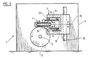
- a drive 13 can also be attached to the yoke 11 and connected to the speedometer roller 7 by means of a transmission belt 15.
- the yoke 11 is connected to the winding machine 1 by means of a preferably cylindrical pin 17 via a carrier 19.
- the carrier 19 also has a preferably cylindrical bore 21, the diameter of which is larger than the diameter of the pin 17.
- the connection between the pin 17 and the carrier 19 is made by two O-rings 23 which are placed on the pin 17 at an axial distance and are in contact with the bore 21.
- O-rings with a round cross-section it is of course also possible to use rubber-elastic rings with others, for example oval ones or rectangular, cross-section can be used, or an insert made of rubber-elastic material can fill the entire space between the surface of the pin 17 and the bore 21 (the latter variant not shown).
- the carrier 19 is vertically displaceable on the housing 9 of the winding machine 1, for example in a dovetail groove or the like.
- the rotation of the pin 17 is in the range of angular minutes.
- the tangential displacement of the surface of the pin 17 with respect to the surface of the bore 21 is absorbed by the elasticity of the O-rings 23 forming the connection between the two surfaces.
Landscapes
- Winding Filamentary Materials (AREA)
- Tension Adjustment In Filamentary Materials (AREA)
Applications Claiming Priority (4)
| Application Number | Priority Date | Filing Date | Title |
|---|---|---|---|
| CH4103/88 | 1988-11-04 | ||
| CH410388 | 1988-11-04 | ||
| CH207989A CH678316A5 (en) | 1989-06-02 | 1989-06-02 | Bobbin winder |
| CH2079/89 | 1989-06-02 |
Publications (2)
| Publication Number | Publication Date |
|---|---|
| EP0367726A1 true EP0367726A1 (fr) | 1990-05-09 |
| EP0367726B1 EP0367726B1 (fr) | 1993-01-07 |
Family
ID=25689451
Family Applications (1)
| Application Number | Title | Priority Date | Filing Date |
|---|---|---|---|
| EP89810819A Expired - Lifetime EP0367726B1 (fr) | 1988-11-04 | 1989-11-01 | Dispositif de compensation de l'affaissement de la broche de bobinage dans une machine à bobiner |
Country Status (4)
| Country | Link |
|---|---|
| US (1) | US5004170A (fr) |
| EP (1) | EP0367726B1 (fr) |
| JP (1) | JP2666864B2 (fr) |
| DE (1) | DE58903223D1 (fr) |
Cited By (1)
| Publication number | Priority date | Publication date | Assignee | Title |
|---|---|---|---|---|
| EP0955261A1 (fr) * | 1998-04-07 | 1999-11-10 | Maschinenfabrik Rieter Ag | Surveillance de la force de pression entre la bobine et le rouleau tachométrique |
Families Citing this family (5)
| Publication number | Priority date | Publication date | Assignee | Title |
|---|---|---|---|---|
| JP2505140B2 (ja) * | 1991-12-05 | 1996-06-05 | 村田機械株式会社 | 紡糸巻取機 |
| US5533686A (en) * | 1993-11-15 | 1996-07-09 | Maschinenfabrik Rieter Ag | Methods and apparatus for the winding of filaments |
| DE10037833A1 (de) * | 2000-08-03 | 2002-02-14 | Schlafhorst & Co W | Spuleinrichtung für eine Kreuzspulen herstellende Textilmaschine |
| CN116462055B (zh) * | 2023-04-18 | 2024-01-30 | 江苏天明机械集团有限公司 | 一种柔性隔振卷绕装置及应用柔性隔振卷绕装置的卷绕机 |
| DE102024003545A1 (de) * | 2024-10-25 | 2026-04-30 | Oerlikon Textile Gmbh & Co. Kg | Aufspulvorrichtung zum Aufspulen von synthetischen Fäden |
Citations (7)
| Publication number | Priority date | Publication date | Assignee | Title |
|---|---|---|---|---|
| DE693580C (de) * | 1937-09-25 | 1940-07-13 | Barmer Maschinenfabrik Akt Ges | Spulmaschine mit Treibtrommelantrieb der Wickelspule |
| GB1031478A (en) * | 1962-03-01 | 1966-06-02 | Barmag Barmer Maschf | Improvements relating to spool holders for textile winding apparatus |
| DE1629522A1 (de) * | 1966-10-18 | 1971-02-04 | Licentia Gmbh | Wickelvorrichtung aus einem an sich bekannten Wickeldorn zur Herstellung von Rohren aus Bahnen- oder Fadenmaterial |
| DE2446076A1 (de) * | 1973-09-26 | 1975-03-27 | Rieter Ag Maschf | Vorrichtung und verfahren zum aufbau einer rotations-symmetrisch vergleichmaessigten spule |
| DE2458853A1 (de) * | 1974-12-12 | 1976-06-16 | Schlafhorst & Co W | Wickeleinrichtung fuer konische, durch friktion angetriebene kreuzspulen |
| FR2329575A1 (fr) * | 1975-10-30 | 1977-05-27 | Mitsubishi Heavy Ind Ltd | Bobinoir a grande vitesse avec montage perfectionne du cylindre d'entrainement et procede de bobinage |
| EP0160954A1 (fr) * | 1984-05-10 | 1985-11-13 | B a r m a g AG | Bobinoir |
Family Cites Families (5)
| Publication number | Priority date | Publication date | Assignee | Title |
|---|---|---|---|---|
| US492613A (en) * | 1893-02-28 | Island | ||
| FR964615A (fr) * | 1947-04-25 | 1950-08-19 | ||
| BE518748A (fr) * | 1952-04-03 | |||
| US2880027A (en) * | 1957-05-24 | 1959-03-31 | Gen Motors Corp | Resilient coupling for independently rotatable elements |
| JPH0253348B2 (fr) * | 1979-07-10 | 1990-11-16 | Rieter Ag Maschf |
-
1989
- 1989-11-01 EP EP89810819A patent/EP0367726B1/fr not_active Expired - Lifetime
- 1989-11-01 US US07/430,164 patent/US5004170A/en not_active Expired - Fee Related
- 1989-11-01 DE DE8989810819T patent/DE58903223D1/de not_active Expired - Fee Related
- 1989-11-02 JP JP1285065A patent/JP2666864B2/ja not_active Expired - Lifetime
Patent Citations (7)
| Publication number | Priority date | Publication date | Assignee | Title |
|---|---|---|---|---|
| DE693580C (de) * | 1937-09-25 | 1940-07-13 | Barmer Maschinenfabrik Akt Ges | Spulmaschine mit Treibtrommelantrieb der Wickelspule |
| GB1031478A (en) * | 1962-03-01 | 1966-06-02 | Barmag Barmer Maschf | Improvements relating to spool holders for textile winding apparatus |
| DE1629522A1 (de) * | 1966-10-18 | 1971-02-04 | Licentia Gmbh | Wickelvorrichtung aus einem an sich bekannten Wickeldorn zur Herstellung von Rohren aus Bahnen- oder Fadenmaterial |
| DE2446076A1 (de) * | 1973-09-26 | 1975-03-27 | Rieter Ag Maschf | Vorrichtung und verfahren zum aufbau einer rotations-symmetrisch vergleichmaessigten spule |
| DE2458853A1 (de) * | 1974-12-12 | 1976-06-16 | Schlafhorst & Co W | Wickeleinrichtung fuer konische, durch friktion angetriebene kreuzspulen |
| FR2329575A1 (fr) * | 1975-10-30 | 1977-05-27 | Mitsubishi Heavy Ind Ltd | Bobinoir a grande vitesse avec montage perfectionne du cylindre d'entrainement et procede de bobinage |
| EP0160954A1 (fr) * | 1984-05-10 | 1985-11-13 | B a r m a g AG | Bobinoir |
Cited By (1)
| Publication number | Priority date | Publication date | Assignee | Title |
|---|---|---|---|---|
| EP0955261A1 (fr) * | 1998-04-07 | 1999-11-10 | Maschinenfabrik Rieter Ag | Surveillance de la force de pression entre la bobine et le rouleau tachométrique |
Also Published As
| Publication number | Publication date |
|---|---|
| JPH02175569A (ja) | 1990-07-06 |
| JP2666864B2 (ja) | 1997-10-22 |
| DE58903223D1 (de) | 1993-02-18 |
| EP0367726B1 (fr) | 1993-01-07 |
| US5004170A (en) | 1991-04-02 |
Similar Documents
| Publication | Publication Date | Title |
|---|---|---|
| EP3649069A1 (fr) | Dispositif d'enroulement doté d'un cylindre de soutien et unité de réglage de force d'appui ainsi que machine de traitement du fil | |
| EP0165428A2 (fr) | Machine textile avec plusieurs unités de bobinage de fil à vitesse constante sur bobine conique | |
| CH694560A5 (de) | Aufspulvorrichtung. | |
| EP2251291B1 (fr) | Réserve de fil pour un poste de travail d'une machine à filer à bout libre | |
| DE3780188T3 (de) | Spulmaschine. | |
| CH693449A5 (de) | Aufspulmaschine. | |
| EP0367726B1 (fr) | Dispositif de compensation de l'affaissement de la broche de bobinage dans une machine à bobiner | |
| EP0278037B1 (fr) | Machine pour centrer l'équilibrage de corps en rotation | |
| EP4101800A1 (fr) | Unité de réservoir de fil pour un poste de travail d'une machine textile | |
| DE2643060A1 (de) | Vorrichtung zur lagerung eines spulentraegers bei einer schnellspulmaschine | |
| DE2649555C3 (de) | Friktionsantriebsvorrichtung | |
| CH665658A5 (de) | Vorrichtung zum lagern und antreiben eines spinnrotors einer oe-spinnvorrichtung. | |
| EP1718554B1 (fr) | Cylindre d'entrainement pour machine textile produisant des bobines croisees | |
| DE102005025698A1 (de) | Fadenchangiervorrichtung für eine Spuleinrichtung einer Kreuzspulen herstellenden Textilmaschine | |
| DE10150297A1 (de) | Vorrichtung zum Führen oder Aufwickeln eines laufenden Fadens | |
| CH678316A5 (en) | Bobbin winder | |
| EP0378829A1 (fr) | Bobinoir pour embobiner du fil pour machines à filer | |
| EP0955261A1 (fr) | Surveillance de la force de pression entre la bobine et le rouleau tachométrique | |
| EP0199174B1 (fr) | Dispositif pour l'alimentation positive de fils élastomères aux machines textiles | |
| DE2310323A1 (de) | Hochtourige spindelanordnung fuer spinnmaschinen und lagerung fuer derartige spindeln | |
| CH615647A5 (en) | Thread-tension compensator | |
| DE4343866A1 (de) | Spulenrahmen zum Halten einer Spulenhülse | |
| DE102008016014B4 (de) | Hülsenverriegelungsvorrichtung | |
| EP1077893B1 (fr) | Bobineuse munie d'un dispositif de soutien | |
| DE10109570A1 (de) | Einrichtung zum Entkoppeln von Drehungleichförmigkeiten |
Legal Events
| Date | Code | Title | Description |
|---|---|---|---|
| PUAI | Public reference made under article 153(3) epc to a published international application that has entered the european phase |
Free format text: ORIGINAL CODE: 0009012 |
|
| AK | Designated contracting states |
Kind code of ref document: A1 Designated state(s): CH DE FR GB IT LI |
|
| 17P | Request for examination filed |
Effective date: 19900320 |
|
| EL | Fr: translation of claims filed | ||
| 17Q | First examination report despatched |
Effective date: 19920525 |
|
| GRAA | (expected) grant |
Free format text: ORIGINAL CODE: 0009210 |
|
| AK | Designated contracting states |
Kind code of ref document: B1 Designated state(s): CH DE FR GB IT LI |
|
| REF | Corresponds to: |
Ref document number: 58903223 Country of ref document: DE Date of ref document: 19930218 |
|
| GBT | Gb: translation of ep patent filed (gb section 77(6)(a)/1977) |
Effective date: 19930222 |
|
| ITF | It: translation for a ep patent filed | ||
| ET | Fr: translation filed | ||
| PLBE | No opposition filed within time limit |
Free format text: ORIGINAL CODE: 0009261 |
|
| STAA | Information on the status of an ep patent application or granted ep patent |
Free format text: STATUS: NO OPPOSITION FILED WITHIN TIME LIMIT |
|
| 26N | No opposition filed | ||
| PGFP | Annual fee paid to national office [announced via postgrant information from national office to epo] |
Ref country code: GB Payment date: 19951016 Year of fee payment: 7 |
|
| PGFP | Annual fee paid to national office [announced via postgrant information from national office to epo] |
Ref country code: FR Payment date: 19951019 Year of fee payment: 7 |
|
| PG25 | Lapsed in a contracting state [announced via postgrant information from national office to epo] |
Ref country code: GB Effective date: 19961101 |
|
| GBPC | Gb: european patent ceased through non-payment of renewal fee |
Effective date: 19961101 |
|
| PG25 | Lapsed in a contracting state [announced via postgrant information from national office to epo] |
Ref country code: FR Effective date: 19970731 |
|
| REG | Reference to a national code |
Ref country code: FR Ref legal event code: ST |
|
| PGFP | Annual fee paid to national office [announced via postgrant information from national office to epo] |
Ref country code: DE Payment date: 19991025 Year of fee payment: 11 Ref country code: CH Payment date: 19991025 Year of fee payment: 11 |
|
| PG25 | Lapsed in a contracting state [announced via postgrant information from national office to epo] |
Ref country code: LI Free format text: LAPSE BECAUSE OF NON-PAYMENT OF DUE FEES Effective date: 20001130 Ref country code: CH Free format text: LAPSE BECAUSE OF NON-PAYMENT OF DUE FEES Effective date: 20001130 |
|
| REG | Reference to a national code |
Ref country code: CH Ref legal event code: PL |
|
| PG25 | Lapsed in a contracting state [announced via postgrant information from national office to epo] |
Ref country code: DE Free format text: LAPSE BECAUSE OF NON-PAYMENT OF DUE FEES Effective date: 20010801 |
|
| PG25 | Lapsed in a contracting state [announced via postgrant information from national office to epo] |
Ref country code: IT Free format text: LAPSE BECAUSE OF NON-PAYMENT OF DUE FEES;WARNING: LAPSES OF ITALIAN PATENTS WITH EFFECTIVE DATE BEFORE 2007 MAY HAVE OCCURRED AT ANY TIME BEFORE 2007. THE CORRECT EFFECTIVE DATE MAY BE DIFFERENT FROM THE ONE RECORDED. Effective date: 20051101 |