EP0160991A2 - Optische Vorrichtung zur durchgehenden Messung von Reaktionsflüssigkeiten - Google Patents
Optische Vorrichtung zur durchgehenden Messung von Reaktionsflüssigkeiten Download PDFInfo
- Publication number
- EP0160991A2 EP0160991A2 EP85105674A EP85105674A EP0160991A2 EP 0160991 A2 EP0160991 A2 EP 0160991A2 EP 85105674 A EP85105674 A EP 85105674A EP 85105674 A EP85105674 A EP 85105674A EP 0160991 A2 EP0160991 A2 EP 0160991A2
- Authority
- EP
- European Patent Office
- Prior art keywords
- measuring
- liquid
- reaction
- suction
- plate
- Prior art date
- Legal status (The legal status is an assumption and is not a legal conclusion. Google has not performed a legal analysis and makes no representation as to the accuracy of the status listed.)
- Granted
Links
Images


Classifications
-
- G—PHYSICS
- G01—MEASURING; TESTING
- G01N—INVESTIGATING OR ANALYSING MATERIALS BY DETERMINING THEIR CHEMICAL OR PHYSICAL PROPERTIES
- G01N35/00—Automatic analysis not limited to methods or materials provided for in any single one of groups G01N1/00 - G01N33/00; Handling materials therefor
- G01N35/02—Automatic analysis not limited to methods or materials provided for in any single one of groups G01N1/00 - G01N33/00; Handling materials therefor using a plurality of sample containers moved by a conveyor system past one or more treatment or analysis stations
- G01N35/025—Automatic analysis not limited to methods or materials provided for in any single one of groups G01N1/00 - G01N33/00; Handling materials therefor using a plurality of sample containers moved by a conveyor system past one or more treatment or analysis stations having a carousel or turntable for reaction cells or cuvettes
-
- G—PHYSICS
- G01—MEASURING; TESTING
- G01N—INVESTIGATING OR ANALYSING MATERIALS BY DETERMINING THEIR CHEMICAL OR PHYSICAL PROPERTIES
- G01N35/00—Automatic analysis not limited to methods or materials provided for in any single one of groups G01N1/00 - G01N33/00; Handling materials therefor
- G01N35/02—Automatic analysis not limited to methods or materials provided for in any single one of groups G01N1/00 - G01N33/00; Handling materials therefor using a plurality of sample containers moved by a conveyor system past one or more treatment or analysis stations
- G01N35/028—Automatic analysis not limited to methods or materials provided for in any single one of groups G01N1/00 - G01N33/00; Handling materials therefor using a plurality of sample containers moved by a conveyor system past one or more treatment or analysis stations having reaction cells in the form of microtitration plates
-
- G—PHYSICS
- G01—MEASURING; TESTING
- G01N—INVESTIGATING OR ANALYSING MATERIALS BY DETERMINING THEIR CHEMICAL OR PHYSICAL PROPERTIES
- G01N35/00—Automatic analysis not limited to methods or materials provided for in any single one of groups G01N1/00 - G01N33/00; Handling materials therefor
- G01N35/10—Devices for transferring samples or any liquids to, in, or from, the analysis apparatus, e.g. suction devices, injection devices
- G01N35/1065—Multiple transfer devices
-
- Y—GENERAL TAGGING OF NEW TECHNOLOGICAL DEVELOPMENTS; GENERAL TAGGING OF CROSS-SECTIONAL TECHNOLOGIES SPANNING OVER SEVERAL SECTIONS OF THE IPC; TECHNICAL SUBJECTS COVERED BY FORMER USPC CROSS-REFERENCE ART COLLECTIONS [XRACs] AND DIGESTS
- Y10—TECHNICAL SUBJECTS COVERED BY FORMER USPC
- Y10T—TECHNICAL SUBJECTS COVERED BY FORMER US CLASSIFICATION
- Y10T436/00—Chemistry: analytical and immunological testing
- Y10T436/11—Automated chemical analysis
- Y10T436/113332—Automated chemical analysis with conveyance of sample along a test line in a container or rack
-
- Y—GENERAL TAGGING OF NEW TECHNOLOGICAL DEVELOPMENTS; GENERAL TAGGING OF CROSS-SECTIONAL TECHNOLOGIES SPANNING OVER SEVERAL SECTIONS OF THE IPC; TECHNICAL SUBJECTS COVERED BY FORMER USPC CROSS-REFERENCE ART COLLECTIONS [XRACs] AND DIGESTS
- Y10—TECHNICAL SUBJECTS COVERED BY FORMER USPC
- Y10T—TECHNICAL SUBJECTS COVERED BY FORMER US CLASSIFICATION
- Y10T436/00—Chemistry: analytical and immunological testing
- Y10T436/25—Chemistry: analytical and immunological testing including sample preparation
- Y10T436/2575—Volumetric liquid transfer
Definitions
- the present invention relates to an optical continuous and automatic measuring apparatus for various kinds of reaction-liquids received in a plurality of microcups which are provided at intervals of a certain distance in a microplate.
- Japanese Patent Publication No. 13907/1981 discloses an optical continuous- and automatic measuring apparatus for the various kinds of the reaction-liquids received in the microcups, in which apparatus, the microplate is made of a transparent material and horizontally transferred to be measured by being subjected to the light beam which is issued from a light source provided under the microplate so as to be directed upward to the bottom surface of the microcups so that the light beam having passed through the microcups is received by a light detector provided over the microplate to perform the measurement of such liquids.
- an optical measuring apparatus characterized by comprising: a plate-like member provided with a plurality of cavities for receiving a reaction-liquid, which cavities are arranged on a straight line at intervals of a certain distance; a first driving mechanism for intermittently transferring the plate-like member by the certain distance of the interval of the plurality of cavities on its each transferring movement in a direction in which the plurality of the cavities are linearly arranged; a rotary member provided over the plate-like member so as to be rotatable in the direction in which the plurality of the cavities are linearly arranged; a plurality of suction nozzles the number of which is identical with that of the cavities, which nozzles are so arranged that they radially project outward from an outer periphery of the rotary member to have their front ends circumferentially spaced a prescribed distance apart from each other, which prescribed distance is substantially equal to or slightly greater than the interval of the plurality of the cavities of the plate-like member; a plurality of measuring cells
- the transferring movement of the plate-like member is synchronized with the rotating movement of the rotary member so that the suction nozzles are sequentially inserted into the reaction-liquids received in the cavities formed on the surface of the plate-like member.
- the suction member gives the measuring cells the negative pressure to automatically suck the reaction-liquids from the cavities of the plate-like member into the measuring cells so that the reaction-liquids are retained in the measuring cells. Then, the measuring cells are brought into a measuring position in which the reaction-liquids received in the transparent measuring cells is automatically measured.
- the measuring cells are brought into a rinsing position in which the rinsing liquid is supplied into each of the measuring cells by the rinsing liquid supplying/discharging member to rinse the inside thereof, so that the rinsing liquid is discharged together with the reaction-liquids form the measuring cells by the rinsing liquid supplying/discharging member, whereby the measurements are performed with the use of an accurate length of the optical path of the light beam irrespective of the variation of the amount of the reaction-liquid received in the measuring cell, and further such measurement does not require any man power at all and is performed in a short time.
- the opening of the measuring cell opens to the side surface of the age provided in a supporting plate which has its side surface hermetically brought into slidable contact with a side surface of the rotary member, which suction passage has two openings one of which opens to a position communicating with the opening of the measuring cell and the other of which two openings opens to another position communicating with the suction pipe connected to a negative pressure source;
- the rinsing liquid supplying/discharging member comprises a rinsing liquid supplying pipe communicating with a front end of the suction nozzle, a liquid discharging passage and a liquid discharging pipe both provided in the supporting member, which liquid discharging passage has two openings one of which opens to a position communicating with the opening of the measuring cell and the other of which two openings opens to another position communicating with the liquid discharging pipe.
- the above embodiment of the present invention is characterized in that: the rinsing liquid supplying pipe is provided with a slit in its front end, which slit has a sufficient width to enable the suction nozzle to pass through the slit when the suction nozzle is transferred in the rotational direction of the rotarv membe, so that the rinsing liquid retained in this slit under the effect of the surface tention of the rinsing liquid is introduced into the suction nozzle and the measuring cell to rinse both the inside and the outside of the suction nozzle and the inside of the measuring cell.
- the opening of the liquid discharging passage which opening communicates with the opening of the measuring cell, is constructed of an arc-shaped opening formed in the side surface of the supporting member so that a discharging operation of the reaction-liquid is started just before starting a supplying operation of the rinsing liquid to the measuring cell and a discharging operation of the rinsing liquid supplied in the measuring cell is continued after the measuring cell passed its rinsing position to make it possible that the liquid received in the measuring cell is completely discharged.
- another embodiment of the present invention is characterized in taht: the plate-like member is movable in reciprocating manner in both its longitudinal and transverse directions; and the suction nozzles are provided in a portion of the outer periphery of the rotary member, wherein, in case that the plate-like member is under its returning movement, the suction nozzles do not abut against the plate-like member so that the returning movement of the plate-like member is free from the suction nozzles.
- another embodiment of the present invention is characterized in that: a front end of a connecting portion of the suction nozzle to the measuring cell is inserted into the measuring cell, in the vicinity of which front end are provided a plurality of through-holes which are circumferentially spaced a suitable distance apart from each other, so that the reaction-liquid is prevented from being transferred directly to a discharging opening of the measuring cell, i.e., prevented from being directly passed through the measuring cell without being filled in the measuring cell and so that the rinsing operation is sufficiently performed.
- the numeral 1 designates a microplate, on a surface of which a plurality of microcups 2 are uniformly formed at intervals of a certain distance P in both longitudinal and transverse directions thereof.
- microplate 1 is placed on a table 19 as shown in Fig. 1, which table 19 is intermittently moved in. both directions X and Y by the distance P upon its each intermittent movement.
- the numeral 17 designates a slit for positioning the microplate 1 when the microplate 1 is transferred in the direction Y to be stopped at a certain position.
- a stationarily fixed plate 23 is provided alongside the microplate 1 in its transferring direction Y, parallel to which plate 23 and spaced a certain distance apart therefrom is procided a supporting plate l8.
- a rotary shaft 4 is rotatably supported by both the plates l8, 23 so as to be perpendicular to these plates 18, 23.
- a washer plate 13 is fixed to an end of the rotary shaft 4 by screws 14, which end exists in a side in which the microplate 1 exists.
- a disc 3 is mounted in place by means of stopper pins 24 which are mounted on the washer plate 13.
- a spring 16 is interposed between the washer plate 13 and a protecting plate 21 which is adjacent to the disc 3, so that the disc 3 is closely abutted against the supporting plate l8 through the protecting plate 21 and is rotated under such condition.
- the numeral 22 designates a cover for the spring 16.
- a pulley 29 is mounted on the other end of the rotary shaft 4, which end is opposite to the end to which the washer plate 13 is fixed.
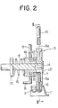
- a detailed construction of the disc 3 is the same as that of another embodiment of the disc 3, shown in Figs. 2 and 3, and therefore will be described later.
- a mounting plate 27 is mounted on the fixed plate 23, on which mounting plate 27 a stepping motor 31 is mounted.
- a pulley 28 is mounted on a rotary shaft of the stepping motor 31.
- a belt 26 runs around the the pulleys 28 and 29, so that the rotational movement of the disc 3 is synchronized with the intermittent transferring movement of the microplate 1 in its direction Y to be intermittently produced by actuation of the stepping motor 31.
- the numeral 30 designates a supporting post for supporting the plates 18, 23.
- the numerals 32 and 33 designate a light source and a light detector, respectively. As shown in Fig.
- the light source 32 and the light detector 33 are so arranged that, when the measuring cell 5 is placed in a position 5b, the measuring cell 5 is interposed therebetween, whereby a light beam issued from the light source 32 passes through an opening 34 of the fixed plate 23 to be projected on the measuring cell 5 and the reaction-liquid therein. Thereafter, the light beam having passed through the reaction-liquid and the measuring cell 5 is received by the light detector 33 so that components of the thus obtained ligt beam are measured by a measuring/recording device (not shown).
- the microplate 1 in the microcups 2 of which the reaction-liquid has been received, is intermittently transferred in the direction Y shown in Figs. 1 and 3 by the distance P upon each intermittent movement of the microplate 1 by means of the driving mechanism (not shown), while the rotational movement of the disc 3 is synchronized with such intermittent transferring movement of the microplate 1 to be continued by the distance P each time it is produced by actuation of the stepping motor 31 in a direction shown by an arrow in Fig. 3.
- the suction nozzle 6 of the measuring cell 5 is inserted into the microcups 2 of the microplate 1 and brought into a sucking position 5a as shown in Fig. 3, the discharging opening 7 of the upper portion of the measuring cell 5 is coincident with the opening of the suction passage 11 of the supporting plate 18. Since the negative pressure is always given to the suction passage 11 through the suction pipe 8, the reaction-liquid received in the microcup 2 is sucked into the measuring cell 5 at the sucking position 5a as shown in Fig. 2, and then such measuring cell 5 is sequentially transferred into the measuring position 5b in which the light beam is projected on the measuring cell 5 from the light source 32 while the measuring cell 5 stays stationary in the measuring position 5b as shown in Fig. 3. On the basis of an amount of the light beam, which is thus projected on the measuring cell 5 and the reaction-liquid therein and passed therethrough to be received by the light detector 33, the reaction-liquid is measured and further recorded by, a measuring instrument (not shown).
- the suction nozzle 6 connected to such measuring cell 5 is brought into a position 6C as shown with a chain-line in Fig. 3, so that the opening of the suction nozzle 6 communicates with the rinsing liquid supplying pipe 10, whereby the rinsing liquid is supplied from the supplying pipe 10 to the suction nozzle 6 in the position 6C so that the reaction-liquid received in the measuring cell 5 is sucked and discharged together with the thus introduced rinsing liquid from the liquid discharging pipe 9 through the liquid discharging passage 12.
- the microplate 1 is returned its initial position in a direction opposite to its previous transferring direction and then moved in the direction X by the distance P so that measurements of the reaction-liquids received in the second row of the microcups 2 of the microplate 1 are conducted in the same manner as that of the measurements of the first row of the microcups 2. Measurements of the third and the following rows of the microcups 2 are conducted in the same manner as that of the measurements of the first row of l the microcups 2.
- suction nozzles 6 are provided only in a portion of the disc 3 and further above the disc 3 in the returning movement of the microplate 1, such suction nozzles 6 do not abut against the microplate 1 when the microplate 1 is returned in the direction Y, whereby the returning movement of the microplate 1 is not prevented by the suction nozzles 6.
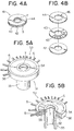
- Fig. 4A shows an embodiment 41 of the disc (3) before the suction nozzles 6 are mounted thereon.
- a front disc portion 42, a middle disc portion 43 and a rear disc portion 44, all of which are made of a transparent glass or a transparent plastic material, are piled up in this order to construct the embodiment, i.e., the disc 41.
- the middle disc portion 43 of the disc 41 may be made of a suitable metal and is radially provided with a predtermined number of slits 45 for forming the plurality of the measuring cells 5, which slits 45 have their openings in an outer periphery of the middle disc portion 43 of the disc 41.
- the rear disc portion 44 of the disc 41 is provided with a predetermined number of through-holes 46 for forming the plurality of the openings 7, which through-holes 46 are provided in a position communicating with the slits 45 of the middle disc portion 43.
- Fig. 5A shows another embodiment 51 of the disc (3).
- the disc 51 is constructed of a front disc portion 52, a middle disc portion 53 and a rear disc portion 54 all of which are made of the transparent glass or transparent plastic material.
- the middle disc portion 53 may be made of an easy-to-form material such as a metal or a plastic and is provided with: a hollow sleeve-like portion 55; a disc portion 56 radially extending from the vicinity of an end of the sleeve-like portion 55; and a flange portion 57 which is provided in an outer periphery of the disc portion 56 and extends axially in both an upper side and a lower side of the disc portion 56 to form cavities in which the front and rear disc portions 52 and 54 are inserted, respectively.
- the disc portion 56 there are provided a predetermined number of slits 58 for forming the measuring cells 5.
- the suction nozzles 6 communicating with these slits 58 of the disc portion 56.
- the discharging openings 7 communicating with the slits 58 of the disc portion 56.
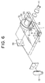
- Fig. 6 shows a measuring condition in which the disc 51 is used, wherein a reflecting mirror 59 is interposed between the light source 11 and the light detector 12.
- Fig. 7 shows another embodiment 61 of the suppor- ing plate (18).
- This embodiment i.e., the supporting plate 61 is provided with an arc-shaped through-hole 62 in its side surface facing the disc 3, which hole 62 communicates with the liquid discharging passage 12.
- the discharging opening 7 communicates with the through-hole 62 of the supporting plate 61 before the measuring cell 5 reaches the rinsing position 5C shown in Fig.
- Figs. 8A and 8B show another embodiment 66 of the rinsing liquid supplying pipe (10).
- This embodiment i.e., the rinsing liquid supplying pipe 66 is constructed of a rinsing liquid transferring pipe 67 and a supplying head 68 mounted on a front end of the transferring pipe 67, in which supplying head 68 there is provided a slit 69 in a transferring direction of the suction nozzle 6 both the inside and the outside of which are rinsed when the suction nozzle 6 passes through the rinsing liquid 70 retained within the slit 69 under the effect of surface tension of the rinsing liquid 70.
- a suction pipe 73 is provided to suction an excess amount of the rinsing liquid 70 in the slit 69 of the supplying head 68.
- Fig. 9 shows another embodiment 71 of the suction nozzle (6).
- This embodiment i.e., the suction nozzle 71 is mounted on the measuring cell 5 by being inserted in the measuring cell 5 in its closed front end in the vicinity of which a plurality of through-holes 72 are circumferentially provided in a peripheral wall of the suction nozzle 71 at intervals of a suitable distance.
- a plurality of through-holes 72 are circumferentially provided in a peripheral wall of the suction nozzle 71 at intervals of a suitable distance.
- suction nozzle 6 since the normal type of the suction nozzle 6 has the opening formed by transversely cutting the front end of the suction nozzle 6, the liquid flows in only one direction so that the reaction-liquid is often transferred directly throuth the plurality of the discharging opening of the measuring cell 5 without being filled in the measuring cell 5 and so taht the rinsing action is not sufficiently conducted.
- the suction nozzle 71 in the suction nozzle 71, the liquid'flows in any directions through the plurality of the through-holes 72, and as a result, the above defect of the suction nozzle 6 is resolved by employing the suction nozzle 71 in place of the suction nozzle 6.
- These suction nozzles 6, 71 are preferably made of a metal such as a stainless steel or a resilient plastic material.
- the measuring apparatus having the above construction according to the present invention, it is possible to continuously, automatically and optically measure a little amount approximately even 0.2 ml of the reaction-liquid received in the microcup 2 of the microplate 1 by using an accurate length of the optical path of the light beam projected on the measuring cell 5 and the reaction-liquid therein.
- 96 specimens of the reaction-liquids received in,96 pieces of the microcups 2 each of which has a dismeter of 6 mm and a length of 10 mm can be measured within 2 seconds in case that an amount of each of the 96 specimens is approximately 0.08 ml.
- the disc 41, 51 are only rotated in the above embodiments of the present invention, it is possible to move them up and down in addition to the above their rotational movements, provided that the suction nozzles 6 are spaced a sufficient distance apart from each other in order to prevent other suction nozzles 6 adjacent to a suction nozzle 6 inserted into the microcup 2 from preventing such inserting movement of the latter nozzle due to their abutting against the microplate 1.
Landscapes
- General Health & Medical Sciences (AREA)
- Physics & Mathematics (AREA)
- Life Sciences & Earth Sciences (AREA)
- Chemical & Material Sciences (AREA)
- Analytical Chemistry (AREA)
- Biochemistry (AREA)
- Immunology (AREA)
- General Physics & Mathematics (AREA)
- Health & Medical Sciences (AREA)
- Pathology (AREA)
- Investigating Or Analysing Materials By The Use Of Chemical Reactions (AREA)
- Automatic Analysis And Handling Materials Therefor (AREA)
- Optical Measuring Cells (AREA)
- Investigating Or Analysing Materials By Optical Means (AREA)
Priority Applications (1)
| Application Number | Priority Date | Filing Date | Title |
|---|---|---|---|
| AT85105674T ATE45225T1 (de) | 1984-05-11 | 1985-05-09 | Optische vorrichtung zur durchgehenden messung von reaktionsfluessigkeiten. |
Applications Claiming Priority (2)
| Application Number | Priority Date | Filing Date | Title |
|---|---|---|---|
| JP59094244A JPS60237369A (ja) | 1984-05-11 | 1984-05-11 | 微小容器内の反応液の連続測定装置 |
| JP94244/84 | 1984-05-11 |
Publications (3)
| Publication Number | Publication Date |
|---|---|
| EP0160991A2 true EP0160991A2 (de) | 1985-11-13 |
| EP0160991A3 EP0160991A3 (en) | 1987-01-07 |
| EP0160991B1 EP0160991B1 (de) | 1989-08-02 |
Family
ID=14104892
Family Applications (1)
| Application Number | Title | Priority Date | Filing Date |
|---|---|---|---|
| EP85105674A Expired EP0160991B1 (de) | 1984-05-11 | 1985-05-09 | Optische Vorrichtung zur durchgehenden Messung von Reaktionsflüssigkeiten |
Country Status (8)
| Country | Link |
|---|---|
| US (1) | US4622208A (de) |
| EP (1) | EP0160991B1 (de) |
| JP (1) | JPS60237369A (de) |
| AT (1) | ATE45225T1 (de) |
| CA (1) | CA1232442A (de) |
| DE (1) | DE3572035D1 (de) |
| DK (1) | DK208385A (de) |
| NO (1) | NO851882L (de) |
Families Citing this family (10)
| Publication number | Priority date | Publication date | Assignee | Title |
|---|---|---|---|---|
| DE3934518A1 (de) * | 1989-10-13 | 1991-04-18 | Lieder Maschinenbau Gmbh & Co | Vorrichtung zum schonenden verpacken |
| US6258326B1 (en) | 1997-09-20 | 2001-07-10 | Ljl Biosystems, Inc. | Sample holders with reference fiducials |
| US6982431B2 (en) | 1998-08-31 | 2006-01-03 | Molecular Devices Corporation | Sample analysis systems |
| US6297018B1 (en) | 1998-04-17 | 2001-10-02 | Ljl Biosystems, Inc. | Methods and apparatus for detecting nucleic acid polymorphisms |
| CN1219048C (zh) * | 1998-02-19 | 2005-09-14 | 医疗电子系统有限公司 | 精子分析系统 |
| AU3649199A (en) | 1998-04-17 | 1999-11-08 | Ljl Biosystems, Inc. | Sample-holding devices and systems |
| US6270726B1 (en) | 1999-09-30 | 2001-08-07 | Dpc Cirrus, Inc. | Tube bottom sensing for small fluid samples |
| US20020132360A1 (en) | 2000-11-17 | 2002-09-19 | Flir Systems Boston, Inc. | Apparatus and methods for infrared calorimetric measurements |
| US6821787B2 (en) | 2000-11-17 | 2004-11-23 | Thermogenic Imaging, Inc. | Apparatus and methods for infrared calorimetric measurements |
| US7517494B2 (en) * | 2003-04-30 | 2009-04-14 | Hewlett-Packard Development Company, L.P. | Test tray and test system for determining response of a biological sample |
Family Cites Families (8)
| Publication number | Priority date | Publication date | Assignee | Title |
|---|---|---|---|---|
| US3178266A (en) * | 1960-10-07 | 1965-04-13 | Warner Lambert Pharmaceutical | Materials handling apparatus |
| US3266298A (en) * | 1963-07-30 | 1966-08-16 | Technicon Instr | Means and method for the identification of samples for blood typing |
| US3622279A (en) * | 1968-06-14 | 1971-11-23 | Hycel Inc | Automatic chemical testing apparatus |
| US3614434A (en) * | 1968-07-17 | 1971-10-19 | Lofstrom James E | Automatic agitating and sample device |
| GB1505312A (en) * | 1975-08-08 | 1978-03-30 | Secr Social Service Brit | Apparatus for use in investigating specimens |
| US4086060A (en) * | 1976-10-22 | 1978-04-25 | Jocelyn Dickson | Disposable manipulative laboratory device for transferring biological fluids |
| US4647432A (en) * | 1982-11-30 | 1987-03-03 | Japan Tectron Instruments Corporation Tokuyama Soda Kabushiki Kaisha | Automatic analysis apparatus |
| US4478094A (en) * | 1983-01-21 | 1984-10-23 | Cetus Corporation | Liquid sample handling system |
-
1984
- 1984-05-11 JP JP59094244A patent/JPS60237369A/ja active Granted
-
1985
- 1985-05-03 US US06/730,035 patent/US4622208A/en not_active Expired - Fee Related
- 1985-05-09 AT AT85105674T patent/ATE45225T1/de not_active IP Right Cessation
- 1985-05-09 DE DE8585105674T patent/DE3572035D1/de not_active Expired
- 1985-05-09 EP EP85105674A patent/EP0160991B1/de not_active Expired
- 1985-05-10 DK DK208385A patent/DK208385A/da not_active Application Discontinuation
- 1985-05-10 CA CA000481301A patent/CA1232442A/en not_active Expired
- 1985-05-10 NO NO851882A patent/NO851882L/no unknown
Also Published As
| Publication number | Publication date |
|---|---|
| DK208385D0 (da) | 1985-05-10 |
| EP0160991B1 (de) | 1989-08-02 |
| NO851882L (no) | 1985-11-12 |
| EP0160991A3 (en) | 1987-01-07 |
| JPS60237369A (ja) | 1985-11-26 |
| DE3572035D1 (en) | 1989-09-07 |
| CA1232442A (en) | 1988-02-09 |
| US4622208A (en) | 1986-11-11 |
| ATE45225T1 (de) | 1989-08-15 |
| DK208385A (da) | 1985-11-12 |
| JPH0263188B2 (de) | 1990-12-27 |
Similar Documents
| Publication | Publication Date | Title |
|---|---|---|
| JP3390001B2 (ja) | 多分析物試験ビヒクル | |
| US5104807A (en) | Analyzing apparatus in which liquid can be stirred and analyzing method thereof | |
| US4313735A (en) | Automatic chemical analyzing method and apparatus | |
| EP0260136B1 (de) | Apparatur für chemische Reaktionen | |
| US4495149A (en) | Optical-type automatic analyzing and measuring apparatus | |
| EP0417305A1 (de) | Analysevorrichtung eines flüssigen musters sowie analyseverfahren von flüssigen mustern unter verwendung dieser vorrichtung | |
| EP0160991B1 (de) | Optische Vorrichtung zur durchgehenden Messung von Reaktionsflüssigkeiten | |
| EP1767950A1 (de) | Verfahren und Vorrichtung zur präzisen Positionierung einer Pipettiervorrichtung | |
| JPH03186762A (ja) | 複式テストストリップのためのテストストリップ評価装置 | |
| JPH0275956A (ja) | 血清中の抗体又は抗原を酵素抗体法で検出することによって生物学的分析を行う装置 | |
| RU2304276C2 (ru) | Устройство для автоматизированного анализа жидкого образца | |
| US4801187A (en) | Liquid light tube end cap assembly | |
| EP0661532A2 (de) | Küvette | |
| JPS6345068B2 (de) | ||
| US5292482A (en) | Automatic analyzing apparatus and automatic analyzing method | |
| JPH01134234A (ja) | 自動化学分析装置 | |
| JPS6276465A (ja) | 生化学自動分析装置 | |
| JPH0536222Y2 (de) | ||
| JPS63212869A (ja) | 自動化学分析装置 | |
| JPS6165123A (ja) | 光フアイバ−による着色溶液の連続測色方法 | |
| JPS61250561A (ja) | 自動化学分析装置 | |
| JPS59131148A (ja) | 電気泳動法における自動比色定量装置 | |
| JPH0776772B2 (ja) | 生化学分析装置の反応ライン装置 | |
| JPH04303771A (ja) | 自動分析装置 | |
| WO2014050947A1 (ja) | 検査チップおよび検査装置 |
Legal Events
| Date | Code | Title | Description |
|---|---|---|---|
| PUAI | Public reference made under article 153(3) epc to a published international application that has entered the european phase |
Free format text: ORIGINAL CODE: 0009012 |
|
| AK | Designated contracting states |
Designated state(s): AT BE CH DE FR GB IT LI NL SE |
|
| PUAL | Search report despatched |
Free format text: ORIGINAL CODE: 0009013 |
|
| AK | Designated contracting states |
Kind code of ref document: A3 Designated state(s): AT BE CH DE FR GB IT LI NL SE |
|
| 17P | Request for examination filed |
Effective date: 19870418 |
|
| 17Q | First examination report despatched |
Effective date: 19880810 |
|
| GRAA | (expected) grant |
Free format text: ORIGINAL CODE: 0009210 |
|
| AK | Designated contracting states |
Kind code of ref document: B1 Designated state(s): AT BE CH DE FR GB IT LI NL SE |
|
| REF | Corresponds to: |
Ref document number: 45225 Country of ref document: AT Date of ref document: 19890815 Kind code of ref document: T |
|
| REF | Corresponds to: |
Ref document number: 3572035 Country of ref document: DE Date of ref document: 19890907 |
|
| ITF | It: translation for a ep patent filed | ||
| ET | Fr: translation filed | ||
| PGFP | Annual fee paid to national office [announced via postgrant information from national office to epo] |
Ref country code: FR Payment date: 19900529 Year of fee payment: 6 |
|
| ITTA | It: last paid annual fee | ||
| PGFP | Annual fee paid to national office [announced via postgrant information from national office to epo] |
Ref country code: NL Payment date: 19900531 Year of fee payment: 6 |
|
| PLBE | No opposition filed within time limit |
Free format text: ORIGINAL CODE: 0009261 |
|
| STAA | Information on the status of an ep patent application or granted ep patent |
Free format text: STATUS: NO OPPOSITION FILED WITHIN TIME LIMIT |
|
| 26N | No opposition filed | ||
| PGFP | Annual fee paid to national office [announced via postgrant information from national office to epo] |
Ref country code: SE Payment date: 19910424 Year of fee payment: 7 |
|
| PGFP | Annual fee paid to national office [announced via postgrant information from national office to epo] |
Ref country code: DE Payment date: 19910425 Year of fee payment: 7 |
|
| PGFP | Annual fee paid to national office [announced via postgrant information from national office to epo] |
Ref country code: GB Payment date: 19910429 Year of fee payment: 7 |
|
| PGFP | Annual fee paid to national office [announced via postgrant information from national office to epo] |
Ref country code: AT Payment date: 19910529 Year of fee payment: 7 |
|
| PGFP | Annual fee paid to national office [announced via postgrant information from national office to epo] |
Ref country code: CH Payment date: 19910607 Year of fee payment: 7 |
|
| PGFP | Annual fee paid to national office [announced via postgrant information from national office to epo] |
Ref country code: BE Payment date: 19910628 Year of fee payment: 7 |
|
| PG25 | Lapsed in a contracting state [announced via postgrant information from national office to epo] |
Ref country code: NL Effective date: 19911201 |
|
| NLV4 | Nl: lapsed or anulled due to non-payment of the annual fee | ||
| PG25 | Lapsed in a contracting state [announced via postgrant information from national office to epo] |
Ref country code: FR Effective date: 19920131 |
|
| REG | Reference to a national code |
Ref country code: FR Ref legal event code: ST |
|
| PG25 | Lapsed in a contracting state [announced via postgrant information from national office to epo] |
Ref country code: GB Effective date: 19920509 Ref country code: AT Effective date: 19920509 |
|
| PG25 | Lapsed in a contracting state [announced via postgrant information from national office to epo] |
Ref country code: SE Effective date: 19920510 |
|
| PG25 | Lapsed in a contracting state [announced via postgrant information from national office to epo] |
Ref country code: LI Effective date: 19920531 Ref country code: CH Effective date: 19920531 Ref country code: BE Effective date: 19920531 |
|
| BERE | Be: lapsed |
Owner name: EISAI CO. LTD Effective date: 19920531 |
|
| GBPC | Gb: european patent ceased through non-payment of renewal fee |
Effective date: 19920509 |
|
| REG | Reference to a national code |
Ref country code: CH Ref legal event code: PL |
|
| PG25 | Lapsed in a contracting state [announced via postgrant information from national office to epo] |
Ref country code: DE Effective date: 19930202 |
|
| EUG | Se: european patent has lapsed |
Ref document number: 85105674.7 Effective date: 19921204 |