EP0161531A2 - Tambour de transfert pour le transport de feuilles - Google Patents
Tambour de transfert pour le transport de feuilles Download PDFInfo
- Publication number
- EP0161531A2 EP0161531A2 EP85104762A EP85104762A EP0161531A2 EP 0161531 A2 EP0161531 A2 EP 0161531A2 EP 85104762 A EP85104762 A EP 85104762A EP 85104762 A EP85104762 A EP 85104762A EP 0161531 A2 EP0161531 A2 EP 0161531A2
- Authority
- EP
- European Patent Office
- Prior art keywords
- sheet
- transfer drum
- rubber suction
- support
- suction cups
- Prior art date
- Legal status (The legal status is an assumption and is not a legal conclusion. Google has not performed a legal analysis and makes no representation as to the accuracy of the status listed.)
- Granted
Links
- 230000002745 absorbent Effects 0.000 claims description 2
- 239000002250 absorbent Substances 0.000 claims description 2
- 239000000123 paper Substances 0.000 description 18
- 101150038956 cup-4 gene Proteins 0.000 description 4
- 230000001914 calming effect Effects 0.000 description 2
- 238000000034 method Methods 0.000 description 2
- 206010038743 Restlessness Diseases 0.000 description 1
- 238000009825 accumulation Methods 0.000 description 1
- 239000000969 carrier Substances 0.000 description 1
- 230000000694 effects Effects 0.000 description 1
- 239000000463 material Substances 0.000 description 1
- 238000005201 scrubbing Methods 0.000 description 1
- 239000007787 solid Substances 0.000 description 1
- 239000002699 waste material Substances 0.000 description 1
Images

Classifications
-
- B—PERFORMING OPERATIONS; TRANSPORTING
- B41—PRINTING; LINING MACHINES; TYPEWRITERS; STAMPS
- B41F—PRINTING MACHINES OR PRESSES
- B41F21/00—Devices for conveying sheets through printing apparatus or machines
- B41F21/10—Combinations of transfer drums and grippers
- B41F21/102—Combinations of transfer drums and grippers with pneumatic means
-
- Y—GENERAL TAGGING OF NEW TECHNOLOGICAL DEVELOPMENTS; GENERAL TAGGING OF CROSS-SECTIONAL TECHNOLOGIES SPANNING OVER SEVERAL SECTIONS OF THE IPC; TECHNICAL SUBJECTS COVERED BY FORMER USPC CROSS-REFERENCE ART COLLECTIONS [XRACs] AND DIGESTS
- Y10—TECHNICAL SUBJECTS COVERED BY FORMER USPC
- Y10S—TECHNICAL SUBJECTS COVERED BY FORMER USPC CROSS-REFERENCE ART COLLECTIONS [XRACs] AND DIGESTS
- Y10S271/00—Sheet feeding or delivering
- Y10S271/90—Stripper
Definitions
- the invention relates to a transfer drum for sheet transport from one printing unit to another.
- Either a transfer drum is provided between two printing units, or three are arranged, the middle one usually having a diameter that is twice as large as in the two outer transfer drums.
- the larger transfer drum can also be used as a storage drum for perfecting.
- the guiding of the sheets on the transfer drums is not without problems. For example, when a sheet is transferred from the second transfer drum to the third, there is often unrest in the sheet guide, so that the freshly printed sheet side is smeared on the surface of the third transfer drum. One then speaks of the bow protruding because after its handover, due to its own weight, it slides down the outer surface of the second transfer drum.
- Stiffer sheets and cardboard also try not to adapt to the curvature of the surface of the transfer drum.
- the radially outward bow ends can meet components that are attached in the area of the transfer drum, such as trusses, light eyes, blow poles etc. The bows are not only smeared, but even damaged.
- the aim is to ensure that the sheet is transported safely and without greasing and damage.
- the invention In addition to calming the sheet travel, the invention also avoids downtimes for replacing the rubber suction cups and the accumulation of waste due to errors in the transfer of the sheets from the transfer drum to the transfer drum or from the transfer drum to the printing cylinder.
- the paper carrier After the sheet is released from the rubber suction device, the paper carrier prevents it from coming into contact again, so that the sheet rolls on the supporting surface of the paper holder and is not supported on the suction lip of the rubber suction device. The bow can therefore not damage the rubber suction cup.
- the support edge of the paper carrier and suction lips of the rubber suction cups are in one plane.
- the supporting edge of the paper carrier is of arcuate design and runs from the plane of the suction lips in the radial direction into the transfer drum when the sheet is sucked in.
- the paper support can advantageously be designed as a support plate or as a support wheel. A particularly calm bow feel tion can be reached if, seen in the axial direction of the transfer drum, a paper support is provided next to each rubber suction cup.
- a particularly expedient embodiment of the invention serves to improve the sheet travel when transferring the sheet from the second to the third transfer drum.
- the improvement is that a double-diameter transfer drum, which is arranged between two single-diameter transfer drums, has rubber suction rows which are offset by 180 ° and can be adjusted to the sheet format, and that a support plate is attached to the suction body next to each rubber suction device .
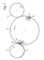
- the sheet transfer unit according to Figure 1 consists of the transfer drum 1, the middle transfer drum 2 and the third transfer drum 3.
- the middle transfer drum 2 has a double diameter. It is left with two evenly distributed on the circumference, parallel to its axis of rotation fenden rows of rubber suction cups 4 provided. These serve to temporarily hold the rear area of the sheet.
- FIGS 2 and 3 show in front and side view the design of the rubber suction cup 4 and a paper carrier 6 in side and front view.
- Suction bodies 8 are fastened on a traverse 7, which runs parallel to the axis of rotation of the transfer drum 2. These each carry a rubber suction device 4.
- the paper carrier 6 is fastened in the form of a support plate 9 by means of rivets 10.
- the support edge 11 of the support plate 9 then lies in one plane with the suction lip 12 of the rubber suction device 4 when the sheet 5 is sucked in.
- the support edge 11 of the support plate 9 runs downward in an arc, i.e. in the radial direction into the transfer drum.
- This arcuate design of the support edge 11 is used to better roll the sheet. It is also designed in an arc shape so that the removed sheet 5 cannot press the suction lip 12 of the rubber suction device 11 against solid parts of the suction body 8. A squeezing and thus damage to the rubber suction cup 4 is not possible due to the arrangement of the support plate 9 and the design of its support edge 11.
- FIGS. 4 and 5 A further embodiment of the paper carrier 6 is shown in FIGS. 4 and 5.
- the suction bodies 8 of the rubber suction cups 4 are in the same manner as in the previously described Embodiment, attached to the cross member 7.
- a support wheel 13 is provided directly next to each rubber suction cup 4. It is rotatably mounted on an axle pin 14 which is fastened to the suction body 8 and runs parallel to the cross member 7.
- the support surface 15 of the support wheel 13 extends so far that the suction lips 12 form a plane with the support surface 15 when the arc is sucked in.
- the arrangement of the support wheel 13 on the suction body 8 relative to the rubber suction device 4 is such that the trailing edge of the sheet 5 is always supported on the support surface 15 of the support wheel 13 without damaging the suction lip 12 of the rubber suction device 4.
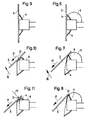
- FIG. 6 illustrates the operation of a paper carrier 6, regardless of whether it is designed as a support plate 9 or as a support wheel 13.
- the sheet 5 rests on the supporting edge 11 in the sucked-in position.
- the rubber suction cup is ventilated, the sheet 5 has consequently become detached and moves on the one hand in the direction of the arrow 16, i.e. it pivots off the rubber suction device 4, the sheet 5 being supported in the region of its rear edge on the support edge 11 of the paper carrier 6.
- the sheet 5 is also pulled in the direction of arrow 17 at the same time.
- the rear pressure-free surface of the sheet 5 slides along the support edge 11 of the paper carrier 6 without being able to damage the suction lip 12 of the rubber suction device 4, as shown in FIG. Particularly when processing cardboard, this guiding of the sheet on its rear edge has a calming effect on the transport movement, so that relative movements between the outer surface of the transfer drum and the printed underside of the cardboard can be avoided.
- FIGS. 9 to 11 show, if no paper supports 6 are provided.
- the sheet 5 then presses Suction lip 12 against an edge of the absorbent body 8.
- the sheet 5 is simultaneously moved in the direction of arrow 16 and arrow 17, as described with reference to FIG. 7. Since in the final phase of the sheet transfer a rigid sheet or cardboard with a fair amount of force, as indicated by the dashed arrow 18, presses in the direction of the rubber suction cup 4, but at the same time also moves in the direction of the arrow 17, a scrubbing movement occurs between the suction lip 12 and an edge of the suction body 8. This has the consequence that after a few thousand pressures the suction lip is damaged at this point in such a way that a hole is formed.
- the paper carrier 6 can also be designed as a bracket with a roughened and chrome-plated surface.
Landscapes
- Feeding Of Articles By Means Other Than Belts Or Rollers (AREA)
- Photoreceptors In Electrophotography (AREA)
- Sheets, Magazines, And Separation Thereof (AREA)
- Liquid Crystal Substances (AREA)
- Fish Paste Products (AREA)
- Delivering By Means Of Belts And Rollers (AREA)
Priority Applications (1)
| Application Number | Priority Date | Filing Date | Title |
|---|---|---|---|
| AT85104762T ATE46656T1 (de) | 1984-05-17 | 1985-04-19 | Umfuehrtrommel fuer den bogentransport. |
Applications Claiming Priority (2)
| Application Number | Priority Date | Filing Date | Title |
|---|---|---|---|
| DE3418303 | 1984-05-17 | ||
| DE19843418303 DE3418303A1 (de) | 1984-05-17 | 1984-05-17 | Umfuehrtrommel fuer den bogentransport |
Publications (3)
| Publication Number | Publication Date |
|---|---|
| EP0161531A2 true EP0161531A2 (fr) | 1985-11-21 |
| EP0161531A3 EP0161531A3 (en) | 1987-06-03 |
| EP0161531B1 EP0161531B1 (fr) | 1989-09-27 |
Family
ID=6236094
Family Applications (1)
| Application Number | Title | Priority Date | Filing Date |
|---|---|---|---|
| EP85104762A Expired EP0161531B1 (fr) | 1984-05-17 | 1985-04-19 | Tambour de transfert pour le transport de feuilles |
Country Status (7)
| Country | Link |
|---|---|
| US (1) | US4615265A (fr) |
| EP (1) | EP0161531B1 (fr) |
| JP (1) | JPS60259450A (fr) |
| AT (1) | ATE46656T1 (fr) |
| AU (1) | AU574153B2 (fr) |
| CA (1) | CA1257621A (fr) |
| DE (1) | DE3418303A1 (fr) |
Cited By (1)
| Publication number | Priority date | Publication date | Assignee | Title |
|---|---|---|---|---|
| EP0769376A1 (fr) * | 1995-10-20 | 1997-04-23 | De La Rue Giori S.A. | Machine d'impression de feuilles |
Families Citing this family (4)
| Publication number | Priority date | Publication date | Assignee | Title |
|---|---|---|---|---|
| DE3608470A1 (de) * | 1986-03-14 | 1987-09-24 | Heidelberger Druckmasch Ag | Umfuehrtrommel fuer den bogentransport in einer druckmaschine |
| JPH05138862A (ja) * | 1991-08-03 | 1993-06-08 | Seiichi Kurosawa | 印刷機の排紙装置 |
| DE19514259A1 (de) * | 1995-04-15 | 1996-10-17 | Roland Man Druckmasch | Verfahren zum Eindrucken von Strichcodes in Druckbogen und Vorrichtung zur Durchführung des Verfahrens |
| DE19713361B4 (de) * | 1997-03-29 | 2007-12-27 | Heidelberger Druckmaschinen Ag | Verfahren und Vorrichtung zum abschmierfreien Führen eines bedruckten Bogens auf einem bogenführenden Zylinder einer Druckmaschine, insbesondere auf einer Wendetrommel einer Bogenrotations-Offsetdruckmaschine, im Schöndruckbetrieb |
Family Cites Families (16)
| Publication number | Priority date | Publication date | Assignee | Title |
|---|---|---|---|---|
| US2325774A (en) * | 1942-07-28 | 1943-08-03 | George I Hohl | Packaging machinery for razor blades and like articles |
| AT183765B (de) * | 1954-03-01 | 1955-11-10 | Carl Neuburger & Comp | Vorrichtung zum Anlegen der Bogen bei Maschinen der Druck-, Papier- oder Kartonagenindustrie |
| DE1277655B (de) * | 1967-02-13 | 1968-09-12 | Windmoeller & Hoelscher | Vorrichtung zum Vereinzeln gestapelter Schlauchstuecke aus Papier oder Kunststoffolie |
| US3643598A (en) * | 1969-01-23 | 1972-02-22 | Nebiolo Spa | Sheet transfer roller for use in multicolor rotary printing presses |
| US3599541A (en) * | 1969-05-22 | 1971-08-17 | Ex Cell O Corp | Container blank variable-speed feeder apparatus |
| US3669445A (en) * | 1970-09-15 | 1972-06-13 | Bernard J Wallis | De-stacking device for sheet metal blanks |
| GB1461781A (en) * | 1973-01-30 | 1977-01-19 | Agfa Gevaert | Dispenser for sheet-like material |
| US3937458A (en) * | 1974-06-03 | 1976-02-10 | H. J. Langen & Sons Ltd. | Rotary transfer mechanism |
| AR206823A1 (es) * | 1974-11-02 | 1976-08-23 | Heidelberger Druckmasch Ag | Tambor de traslacion en maquinas impresoras rotativas de pliegos |
| DE2610480C2 (de) * | 1975-03-12 | 1983-06-30 | Ricoh Co., Ltd., Tokyo | Vorrichtung zur Zuführung des obersten Blattes von einem Blattstapel |
| DE2632243C3 (de) * | 1976-07-17 | 1979-08-30 | Heidelberger Druckmaschinen Ag, 6900 Heidelberg | Auf variable Bogenlängen einstellbare Umführtrommel für Druckmaschinen |
| DE2824733C2 (de) * | 1978-06-06 | 1984-03-15 | Heidelberger Druckmaschinen Ag, 6900 Heidelberg | Umführtrommel für Schön- und Widerdruckmaschinen |
| DD142953A1 (de) * | 1979-05-07 | 1980-07-23 | Guenter Weisbach | Sauger in bogenwendeeinrichtungen von schoen-und widerdruckmaschinen |
| DE3036790C2 (de) * | 1980-09-30 | 1982-11-11 | Heidelberger Druckmaschinen Ag, 6900 Heidelberg | Bogenübergabetrommel für auf Schön- und Widerdruck umstellbare Bogenrotationsdruckmaschinen |
| US4428793A (en) * | 1981-08-25 | 1984-01-31 | Meisei Electric Co., Ltd. | Preparation method for a microscopic specimen and a device therefor |
| DE3208425C2 (de) * | 1982-03-09 | 1984-05-10 | Windmöller & Hölscher, 4540 Lengerich | Rotationsanleger mit Saugwalzen mit abstellbaren Saugern |
-
1984
- 1984-05-17 DE DE19843418303 patent/DE3418303A1/de active Granted
-
1985
- 1985-04-09 AU AU40948/85A patent/AU574153B2/en not_active Ceased
- 1985-04-19 AT AT85104762T patent/ATE46656T1/de not_active IP Right Cessation
- 1985-04-19 EP EP85104762A patent/EP0161531B1/fr not_active Expired
- 1985-04-29 CA CA000480344A patent/CA1257621A/fr not_active Expired
- 1985-05-17 US US06/735,571 patent/US4615265A/en not_active Expired - Lifetime
- 1985-05-17 JP JP60104172A patent/JPS60259450A/ja active Pending
Cited By (3)
| Publication number | Priority date | Publication date | Assignee | Title |
|---|---|---|---|---|
| EP0769376A1 (fr) * | 1995-10-20 | 1997-04-23 | De La Rue Giori S.A. | Machine d'impression de feuilles |
| US5839366A (en) * | 1995-10-20 | 1998-11-24 | De La Rue Giori S.A. | Sheet-fed printing machine |
| CN1076284C (zh) * | 1995-10-20 | 2001-12-19 | 吉奥里大街公司 | 单张纸印刷机 |
Also Published As
| Publication number | Publication date |
|---|---|
| AU4094885A (en) | 1985-11-21 |
| DE3418303A1 (de) | 1985-11-21 |
| JPS60259450A (ja) | 1985-12-21 |
| US4615265A (en) | 1986-10-07 |
| DE3418303C2 (fr) | 1987-09-03 |
| ATE46656T1 (de) | 1989-10-15 |
| CA1257621A (fr) | 1989-07-18 |
| EP0161531B1 (fr) | 1989-09-27 |
| AU574153B2 (en) | 1988-06-30 |
| EP0161531A3 (en) | 1987-06-03 |
Similar Documents
| Publication | Publication Date | Title |
|---|---|---|
| EP0166128B1 (fr) | Machine d'impression rotative pour feuilles avec éléments d'impression disposés en ligne | |
| DE2446188C3 (de) | Bogenführende Mantelfläche von Gegendruckzylindern oder Bogenüberführungszylindern in Rotationsoffsetdruckmaschinen | |
| DE4339344C1 (de) | Vorrichtung für das automatisierte Wechseln von Druckplatten einer Druckmaschine | |
| EP0230032B1 (fr) | Tambour de transfert de feuilles entre les unités d'impression d'une rotative d'impression | |
| CH639346A5 (de) | Doppelbogenzufuhrvorrichtung fuer drucker. | |
| EP0165477A2 (fr) | Revêtement pour cylindre ou tambour transportant des feuilles dans les machines rotatives d'impression offsetet utilisation d'un tel revêtement. | |
| DE2621250B1 (de) | Bogenabfragevorrichtung in einer rotationsdruckmaschine | |
| EP0158816B1 (fr) | Rotative pour feuilles pour imprimer à retiration ou en plusieurs couleurs | |
| DE2065252B2 (de) | Vorrichtung zum Vereinzeln von Bogen eines Bogenstapel | |
| EP0769376A1 (fr) | Machine d'impression de feuilles | |
| EP0839649A2 (fr) | Tambour de transfert dans une machine à imprimer à feuilles | |
| DE2824733C2 (de) | Umführtrommel für Schön- und Widerdruckmaschinen | |
| EP0679513A2 (fr) | Dispositif de guidage d'un support d'impression | |
| DE2804970A1 (de) | Druckvorrichtung | |
| EP0161531B1 (fr) | Tambour de transfert pour le transport de feuilles | |
| EP0000011B2 (fr) | Machine rotative pour imprimer des feuilles. | |
| DE941484C (de) | Greifvorrichtung fuer Druckmaschinen | |
| DE1152425B (de) | Druckerpresse | |
| DE4113362C2 (de) | Umdruckmaschine | |
| DD229360A1 (de) | Blaslufttrommel als uebergabetrommel und auslagetrommel an bogenverarbeitenden maschinen | |
| EP0150355B1 (fr) | Procédé d'impression à retiration et machine d'impression offset à feuilles pour la mise en oeuvre du procédé | |
| EP0337079B1 (fr) | Procédé et dispositif d'enroulage de bandes de matériau, notamment de bandes de papier ou de carton | |
| EP0968821A2 (fr) | Cylindre à transport des feuilles dans une presse à feuilles rotative | |
| CH651500A5 (en) | Sheet-fed rotary printing machine having at least one printing unit | |
| DE2314302B2 (de) | Verfahren und einrichtung zum erzielen eines einwandfreien druckes in einem doppeldruckwerk einer mehrfarben- bogenrotations-offsetdruckmaschine |
Legal Events
| Date | Code | Title | Description |
|---|---|---|---|
| PUAI | Public reference made under article 153(3) epc to a published international application that has entered the european phase |
Free format text: ORIGINAL CODE: 0009012 |
|
| 17P | Request for examination filed |
Effective date: 19850419 |
|
| AK | Designated contracting states |
Designated state(s): AT BE CH FR GB IT LI NL SE |
|
| PUAL | Search report despatched |
Free format text: ORIGINAL CODE: 0009013 |
|
| AK | Designated contracting states |
Kind code of ref document: A3 Designated state(s): AT BE CH FR GB IT LI NL SE |
|
| 17Q | First examination report despatched |
Effective date: 19880811 |
|
| GRAA | (expected) grant |
Free format text: ORIGINAL CODE: 0009210 |
|
| AK | Designated contracting states |
Kind code of ref document: B1 Designated state(s): AT BE CH FR GB IT LI NL SE |
|
| REF | Corresponds to: |
Ref document number: 46656 Country of ref document: AT Date of ref document: 19891015 Kind code of ref document: T |
|
| ITF | It: translation for a ep patent filed | ||
| ET | Fr: translation filed | ||
| GBT | Gb: translation of ep patent filed (gb section 77(6)(a)/1977) | ||
| PLBE | No opposition filed within time limit |
Free format text: ORIGINAL CODE: 0009261 |
|
| STAA | Information on the status of an ep patent application or granted ep patent |
Free format text: STATUS: NO OPPOSITION FILED WITHIN TIME LIMIT |
|
| 26N | No opposition filed | ||
| ITTA | It: last paid annual fee | ||
| PGFP | Annual fee paid to national office [announced via postgrant information from national office to epo] |
Ref country code: AT Payment date: 19920408 Year of fee payment: 8 |
|
| PGFP | Annual fee paid to national office [announced via postgrant information from national office to epo] |
Ref country code: BE Payment date: 19920410 Year of fee payment: 8 |
|
| PGFP | Annual fee paid to national office [announced via postgrant information from national office to epo] |
Ref country code: SE Payment date: 19920414 Year of fee payment: 8 |
|
| PGFP | Annual fee paid to national office [announced via postgrant information from national office to epo] |
Ref country code: NL Payment date: 19920430 Year of fee payment: 8 |
|
| PG25 | Lapsed in a contracting state [announced via postgrant information from national office to epo] |
Ref country code: AT Effective date: 19930419 |
|
| PG25 | Lapsed in a contracting state [announced via postgrant information from national office to epo] |
Ref country code: SE Effective date: 19930420 |
|
| PG25 | Lapsed in a contracting state [announced via postgrant information from national office to epo] |
Ref country code: BE Effective date: 19930430 |
|
| BERE | Be: lapsed |
Owner name: HEIDELBERGER DRUCKMASCHINEN A.G. Effective date: 19930430 |
|
| PG25 | Lapsed in a contracting state [announced via postgrant information from national office to epo] |
Ref country code: NL Effective date: 19931101 |
|
| NLV4 | Nl: lapsed or anulled due to non-payment of the annual fee | ||
| EUG | Se: european patent has lapsed |
Ref document number: 85104762.1 Effective date: 19931110 |
|
| PGFP | Annual fee paid to national office [announced via postgrant information from national office to epo] |
Ref country code: GB Payment date: 20010323 Year of fee payment: 17 |
|
| PGFP | Annual fee paid to national office [announced via postgrant information from national office to epo] |
Ref country code: FR Payment date: 20010420 Year of fee payment: 17 |
|
| PGFP | Annual fee paid to national office [announced via postgrant information from national office to epo] |
Ref country code: CH Payment date: 20010504 Year of fee payment: 17 |
|
| REG | Reference to a national code |
Ref country code: GB Ref legal event code: IF02 |
|
| PG25 | Lapsed in a contracting state [announced via postgrant information from national office to epo] |
Ref country code: GB Free format text: LAPSE BECAUSE OF NON-PAYMENT OF DUE FEES Effective date: 20020419 |
|
| PG25 | Lapsed in a contracting state [announced via postgrant information from national office to epo] |
Ref country code: LI Free format text: LAPSE BECAUSE OF NON-PAYMENT OF DUE FEES Effective date: 20020430 Ref country code: CH Free format text: LAPSE BECAUSE OF NON-PAYMENT OF DUE FEES Effective date: 20020430 |
|
| GBPC | Gb: european patent ceased through non-payment of renewal fee |
Effective date: 20020419 |
|
| REG | Reference to a national code |
Ref country code: CH Ref legal event code: PL |
|
| PG25 | Lapsed in a contracting state [announced via postgrant information from national office to epo] |
Ref country code: FR Free format text: LAPSE BECAUSE OF NON-PAYMENT OF DUE FEES Effective date: 20021231 |
|
| REG | Reference to a national code |
Ref country code: FR Ref legal event code: ST |