EP0162461B1 - Übertragungssystem für digitale Signale - Google Patents
Übertragungssystem für digitale Signale Download PDFInfo
- Publication number
- EP0162461B1 EP0162461B1 EP85106302A EP85106302A EP0162461B1 EP 0162461 B1 EP0162461 B1 EP 0162461B1 EP 85106302 A EP85106302 A EP 85106302A EP 85106302 A EP85106302 A EP 85106302A EP 0162461 B1 EP0162461 B1 EP 0162461B1
- Authority
- EP
- European Patent Office
- Prior art keywords
- format
- signals
- service bit
- service
- data
- Prior art date
- Legal status (The legal status is an assumption and is not a legal conclusion. Google has not performed a legal analysis and makes no representation as to the accuracy of the status listed.)
- Expired - Lifetime
Links
Images


Classifications
-
- H—ELECTRICITY
- H04—ELECTRIC COMMUNICATION TECHNIQUE
- H04L—TRANSMISSION OF DIGITAL INFORMATION, e.g. TELEGRAPHIC COMMUNICATION
- H04L25/00—Baseband systems
- H04L25/38—Synchronous or start-stop systems, e.g. for Baudot code
- H04L25/40—Transmitting circuits; Receiving circuits
- H04L25/49—Transmitting circuits; Receiving circuits using code conversion at the transmitter; using predistortion; using insertion of idle bits for obtaining a desired frequency spectrum; using three or more amplitude levels ; Baseband coding techniques specific to data transmission systems
-
- H—ELECTRICITY
- H04—ELECTRIC COMMUNICATION TECHNIQUE
- H04H—BROADCAST COMMUNICATION
- H04H20/00—Arrangements for broadcast or for distribution combined with broadcast
- H04H20/65—Arrangements characterised by transmission systems for broadcast
- H04H20/76—Wired systems
- H04H20/77—Wired systems using carrier waves
- H04H20/78—CATV [Community Antenna Television] systems
- H04H20/79—CATV [Community Antenna Television] systems using downlink of the CATV systems, e.g. audio broadcast via CATV network
-
- H—ELECTRICITY
- H04—ELECTRIC COMMUNICATION TECHNIQUE
- H04H—BROADCAST COMMUNICATION
- H04H60/00—Arrangements for broadcast applications with a direct linking to broadcast information or broadcast space-time; Broadcast-related systems
- H04H60/09—Arrangements for device control with a direct linkage to broadcast information or to broadcast space-time; Arrangements for control of broadcast-related services
- H04H60/14—Arrangements for conditional access to broadcast information or to broadcast-related services
-
- H—ELECTRICITY
- H04—ELECTRIC COMMUNICATION TECHNIQUE
- H04H—BROADCAST COMMUNICATION
- H04H60/00—Arrangements for broadcast applications with a direct linking to broadcast information or broadcast space-time; Broadcast-related systems
- H04H60/09—Arrangements for device control with a direct linkage to broadcast information or to broadcast space-time; Arrangements for control of broadcast-related services
- H04H60/13—Arrangements for device control affected by the broadcast information
Definitions
- Such systems are used, for example, in wire or cable television systems having many television receivers as terminals.
- a transmission system using a cable television network is described by Y. Kojima et al. in IEEE Transactions on Consumer Electronics, Vol. CE-30, No. 3, August 1984, pages 462-466 under the title "A New Digital Audio and Data Transmission System Using the CATV Network".
- the system is arranged to transmit frames of a composite digital signal including frame synchronizing signals, service bit signals and information signals.
- Each frame (designated as “super frame” in the mentioned article) has 256 words (designated as "frames” in the mentioned article), each word comprising 8 synchronizing bits, 4 service bits and 156 data bits, i.e. a sum of 168 bits.
- the related digital signal receiving system is arranged to receive such frames.
- DE-A-31 26 880 describes a digital signal transmitting system, especially for satellite broadcast, which is arranged to transmit words (designated as "main frames" (Hauptrahmen)) of 320 bits each, and each comprising a synchronizing signal, service bit signals and information signals.
- the service bits of a predetermined number of words are collected to build a unit of service bits which is called a subframe.
- This unity has the same structure as a word ("main frame"). All subframes have the same structure.
- the digital transmitting system is arranged to provide service bit signals in one of a plurality of predetermined service bit formats within each frame.
- the digital signal receiveing system of the present invention is arranged to evaluate different predetermined service bit formats which are received in unities of a frame.
- each format By providing different formats of service bit signals, each format extending over one frame of the composite digital signal, it is possible to change the service bit information with each frame.
- One of a plurality of new features of such systems is that it is possible to address a large number of terminals, for example one million terminals, at high speed. Additionally it is possible to transmit a descrambling key code to each terminal together with the address number of that terminal. Informations concerning a terminal number, a group number and a tier level can be transmitted independently from each other.
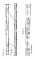
- each word is formed of 168 bits and comprises a word synchronizing signal "Word Sync", for example, of 8 bits, a service bit signal portion “SB” formed of 4 bits SB1 to SB4, a data portion "DATA" of 128 bits (providing 4 channels of data with each channel being formed of 32 bits), and an error check code "ECC” of 28 bits (with the error check code for each of the 4 channels being formed of 7 bits).
- Word Sync word synchronizing signal
- SB service bit signal portion
- DATA data portion
- ECC error check code
- the data DATA and error check code ECC of each channel are respectively re-arranged at every bit, that is, the data and error check codes for the several channels are subjected to so-called bit-interleaving processing.
- Fig. 2 shows that, in a data format of a frame of a digital signal used in accordance with this invention, each frame is formed of 256 words, with each word having the data format shown in Figs. 1A and 1B.
- the first word is formed of a frame sync signal "Frame Sync”, service bits SB, data DATA and an error check code ECC
- the second word is formed of a word sync signal "Word Sync (1)", service bits SB, data and an error check code ECC.
- a third word is formed of a word sync signal "Word Sync (2)", service bits SB, data and an error check code ECC.
- the last or 256th word is formed of a word sync signal "Word Sync (255)", service bits SB, data DATA and an error check code ECC.
- the service bits portion of 4 bits assigned to each word aggregates 1024 bits per frame.
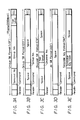
- Figs. 3A to 3E Five kinds of frame formats in which the service bits SB are used to transmit control data are shown in Figs. 3A to 3E. More particularly, a unique service format (USF) is shown in Fig. 3A, a group service format (GSF) is shown in Fig. 3B, a channel service format (CSF) is shown in Fig. 3C, an all service format (ASF) is shown in Fig. 3D, and a scrambling key code format (SKF) is sown in Fig. 3E.
- USF unique service format
- GSF group service format
- CSF channel service format
- ASF all service format
- SBF scrambling key code format
- the legend "Header” refers to a portion of the format which identifies the kind of the respective format; and, in each of Figs. 3A,3B,3D and 3E, the legend “Command” refers to the portion of the format by which a television receiver is commanded to operate.
- the legend "Group No.” refers to the number of a group of receivers having a common characteristic, such as, the area in which the television receivers are situated, or the occupations of the subscribers, or the like.
- the legend "Terminal No.” refers to the address number assigned to a particular television receiver.
- the legend "Tier Level” refers to the condition of the contract for the respective subscriber or television receiver. For example, if the "Tier Level" of the contract is below a predetermined level, the television receiver covered by such contract will be able to receive a broadcast or transmitted signal which is being transmitted on a data channel, such as, a music broadcasting channel, identified in the portion of the format indicated by the legend "Channel No.” on Fig. 3C.
- the legend "Scramble Key Code” identifies a portion of the respective format in which will appear scramble key data, for example, data representing an initial value of an M-sequence code used for descrambling data, as hereinafter described.
- the legend ECC designates an error check code.
- the "Command” indicated on Figs. 3A, 3B,3D and 3E may be any one of the commands shown on Fig. 4, that is, a command "Emergency”, to start emergency broadcasting a command “Announce”, to announce broadcasting, a command "FAX” to start facsimile reception , or a command "DATA" to start the loading of data .
- the formats ASF (Fig. 3D), GSF (Fig. 3B), CSF (Fig. 3C) and SKF (Fig. 3E) are delivered alternately, while, during the second or even-numbered frame, the format USF (Fig. 3A) is delivered alone.
- the manner in which the unique service format (USF) of Fig. 3A is assigned to each television receiver in a memory is illustrated in Figs. 6A to 6D.
- the unique service format of Fig. 6A is assigned to that receiver in the memory for transmission on a service bit SB1.
- control data for controlling a receiver are added to the service bits will be described separately for the transmitter and the receiver.
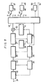
- memories 17 a ,17 b ,17 c corresponding to the all service format (ASF), the channel service format (CSF), and the scrambling key format (SKF), respectively, a group information memory 18 corresponding to the group service format (GSF), and a unique information memory 19 corresponding to the unique service format (USF).
- ASF all service format
- CSF channel service format
- SSF scrambling key format
- GSF group service format
- USF unique information memory 19
- the memory map for the individual information is as shown in Fig. 3A.
- the service bit SB1 has added thereto the unique service format (USF) shown in Fig. 6A
- the service bit SB2 has added thereto the unique service format (USF) shown in Fig. 6B
- the service bit SB3 has added thereto the unique service format (USF) shown in Fig. 6C
- the service bit SB4 has added thereto the unique service format (USF) shown in Fig. 6D.
- group service format contains vacant spaces, as in Fig. 3B so that the cycle of the group service format is very much shorter than that of the unique service format, and transmission at high speed becomes possible.
- Such service bit corresponding to the address number of the receiver is input thereto within one frame period in synchronism with the frame sync signal.
- the service bit is transmitted in the serial format, the sampling of data and the error checking of data can easily be carried out by utilizing the serial port of a microcomputer or microprocessor constituting a controller at the receiver side.
- the data portion is produced and its data format is as shown in the respective one of Figs. 3A to 3E.
- the data sampled in a frame period will be in accordance with one of the formats shown in Figs. 3A to 3E.
- the unique service format (USF) and the other service formats (GSF,CSF,ASF and SKF) are alternately transmitted and these formats are discriminated from one another by the header that is inserted in the start portion of each format.
- a receiver having an address number coincident with that specified by the (Terminal No.) of the format (USF) memorizes the group number specified by the (Group No.) and the level specified by the (Tier Level) and executes the processing specified by the (Command).
- the tier level of the data channel (music broadcasting and so on) to be transmitted by the system embodying this invention is specified in all the receivers. Service for the user is commenced only when the tier level of the channel selected by the user coincides with the tier level specified by the unique service format (USF) and which has been stored therein.
- CSF channel service format
- USF unique service format
- the processing corresponding to the specified command is carried out regardless of the Terminal No.
- the data is descrambled by the specified scramble key code. It is to be noted that the above-described scramble key format (SKF) may be transmitted as a part of the all service format (ASF).
- analog information or data for example, constituting a stereo music signal
- Analog information or data comprised of broadcast communications and announcements is supplied to input terminals 3 and 4.
- Facsimile information or data is supplied to an input terminal 5
- digital information or data such as, that constituting game software and the like, is supplied to an input terminal 6.
- the analog data from input terminals 1 to 4 are supplied to, and converted to digital signals by, analog-to-digital converters (hereinafter simply A/D converters) 7 to 10, respectively.
- the respective digital signals are applied to a multiplexer 12, while the facsimile signal from input terminal 5 is also supplied through a facsimile interface circuit 11 to multiplexer 12.
- the digital data from input terminal 6 is supplied as is to multiplexer 12.
- the input signals are distributed into respective individual channels and subjected to signal processings, such as, the addition of error check codes, bit-interleaving and so on and then delivered therefrom.
- the output signal from multiplexer 12 is supplied to one input terminal of a multiplier 13 and therein multiplied with an M-sequence code signal supplied to another input terminal of multiplier 13 from an M-sequence code oscillator 14.
- M-sequence code oscillator 14 the output signal from multiplexer 12 is scrambled. If n is taken as the stage number of shift register in the M-sequence code oscillator 14, the latter has 2 n -1 bits as the length of its maximum sequence. As shown more particularly in Fig.
- M-sequence code oscillator 14 comprises a shift register 14 a which is formed of a D-type flip-flop, for example, of three stages, and a logic circuit which feeds back a logic value representative of the state of each stage to input terminal SI of the shift register 14 a .
- Such logic circuit is shown to include an exclusive-OR (hereinafter referred to as EOR) circuit 14 b .
- EOR exclusive-OR
- the M-sequence code oscillator 14 produces an M-sequence code of seven cycles, each cycle being represented as "1110100".
- the frequency of the clock signal supplied to the clock terminal CK for use in shifting register 14 a is set properly and the initial phase of the M-sequence code is determined by a frame synchronizing pulse that is supplied from a terminal LP to the load terminal L of shift register 14 a .
- a predetermined preset signal for example, "111" is set at preset terminal A,B and C of shift register 14 a .
- the frame synchronizing pulse and a PN (pseudo noise) code of the M-sequence code oscillator 14 are in phase coincidence with each other.
- the output pulse of seven cycles, such as, "1110100" produced from the M-sequence code oscillator 14 is multiplied with the output of multiplexer 12 so that the multiplier 13 produces data scrambled by the M-sequence code.
- the data and error check code thus scrambled is supplied to a sync/SB (service bit) generator 15 in which the synchronizing signal and the service bits are added to the scrambled data and error check code.
- a controller 16 which may be a microcomputer or microprocessor, outputs from memories 17 a ,17 b ,17 c ,18 and 19 are respectively fed to the sync/SB generator 15 and there selectively added to the service bits.
- the initial value (scramble key data) of the M-sequence code oscillator 14 is set by controller 16 in synchronism with the frame synchronizing signal. This initial value is changed constantly from time to time in order to increase security.
- the filter 20 is used as an equalizer for matching the frequency characteristics of the whole transmitting-receiving system, thereby to remove inter symbol interference.
- A/M-modulator 21 the carrier from an oscillator 22 is modulated by the output signal from filter 20. Accordingly, modulator 21 produces, at its output, an intermediate frequency signal and this signal is supplied through a vestigial side-band filter 23 to a mixing circuit 24. In mixing circuit 24, the intermediate frequency signal is mixed with the local oscillation frequency signal from a local oscillating circuit 25 and is thereby frequency-converted.
- the local oscillation frequency of local oscillating circuit 25 is set higher than a transmitting frequency of a desired channel by the value of the intermediate frequency. Accordingly, the transmission channel is determined by selected the local oscillation frequency.
- the output signal from mixing circuit 24 is delivered through a band-pass filter 26 to an output terminal 27 and the signal developed at the output terminal 27 is transmitted to a so-called head end (not shown) of the cable or CATV system.
- the signal from the head end is transmitted through a CATV transmission line (not shown) to the receiving side.
- the signal transmitted through the CATV transmission line is supplied through an input terminal 31 at the receiving side to a front end 32 in which it is amplified and then converted to an intermediate frequency signal of a predetermined frequency.
- This intermediate frequency signal is supplied to an AM detector, for example, a PLL (phase-locked loop) detector 33, which then demodulates a base band signal.
- the detector may be of the type of Am detector that is normally used in a standard television system, it is preferable to use the mentioned PLL detector 33 in order to avoid any waveform distortion.
- a part of the output signal from PLL detector 33 is supplied to an AGC (automatic gain control) circuit 34 which applies an automatic gain control signal to front end 32.
- AGC automatic gain control
- the output from the PLL detector 33 is supplied to a data recovery circuit 35 in which, on the basis of a clock signal reproduced from the output of the PLL detector 33 by a clock recovery circuit 36, the level of the input signal to circuit 35 is discriminated by the center level of an eye pattern to thereby produce digital data.
- the data thus produced or recovered in circuit 35 is supplied to a succeeding sync/SB separator 37 in which the synchronizing signal and the service bits are separated from the data and supplied to a controller 38.
- the controller 38 which is desirably a microprocessor or microcomputer is adapted to carry out various control operations in synchronism with the synchronizing signal and the control data added to the service bit is stored through the controller 38 in a memory 39.
- the data output from the sync/SB separator 37 is supplied to one input terminal of a multiplier 40 and multiplied in the latter by an M-sequence code signal supplied to the other input terminal of multiplier 40 from an M-sequence code oscillator 41 which may be similar to M-sequence code oscillator 14 of Fig. 7B.
- M-sequence code oscillator 41 which may be similar to M-sequence code oscillator 14 of Fig. 7B.
- the data from multiplier 40 is supplied to a de-multiplexer 42 in which it is subjected to signal processing, such as, rearrangement of data (bit-deinterleaving), error correction and so on.
- the digital signals from de-multiplexer 42 are supplied through switches 43 and 44 to digital-to-analog (D/A) converters 45 and 46, respectively, in which they are converted from digital-to-analog signals and then delivered to output terminals 47 and 48, respectively.
- D/A digital-to-analog
- a facsimile signal is obtained from de-multiplexer 42, such facsimile signal is delivered through a facsimile interface circuit 49 to an output terminal 50.
- digital data such as game software and so on, is directly delivered from de-multiplexer 42 to an output terminal 51.
- the digital signal transmitting system is simple in circuit arrangement and descrambling is possible only when the receiving side is synchronized with the transmitting side so that digital signal transmission of very high security becomes possible.
- the scrambling can be effected at high speed. Furthermore, since the descramble key data (scramble key format) is serially transmitted by utilizing the service bit, such data can be descrambled with ease and at high speed in the receiving side.
- the scramble key data is always transmitted with a cycle shorter than that of the individual data, such as unique service format and so on, the changed scramble key data can be reset immediately.
Landscapes
- Engineering & Computer Science (AREA)
- Signal Processing (AREA)
- Multimedia (AREA)
- Physics & Mathematics (AREA)
- Spectroscopy & Molecular Physics (AREA)
- Computer Networks & Wireless Communication (AREA)
- Time-Division Multiplex Systems (AREA)
- Two-Way Televisions, Distribution Of Moving Picture Or The Like (AREA)
Claims (5)
- Übertragungssystem für digitale Signale, das aus Wörtern zusammengesetzte Rahmen überträgt, wobei jedes Wort zumindest aus Synchronisiersignalen, Servicebitsignalen und Informationssignalen zusammen mit Fehlerprüfkodes zusammengesetzt ist, mit folgenden Baugruppen:- einer Einrichtung (6), die die Synchronisiersignale bereitstellt;- einer Einrichtung (12), welche die Informationssignale zusammen mit den Fehlerprüfkodes liefert;- Einrichtungen (17a, 17b, 17c, 18, 19), welche die Servicebitsignale bereitstellen, wobei die Servicebitsignale der Wörter innerhalb eines Rahmens ein vorgegebenes Format aufweisen und Steuerdaten beinhalten; und- einer Addiereinrichtung (15), welche die Synchronisiersignale, Servicebitsignale und Informationssignale mit den Fehlerprüfkodes zu den Wörtern und Rahmen zusammenfaßt;dadurch gekennzeichnet, daß- jede der Einrichtungen zum Bereitstellen der Servicebitsignale letztere (17a, 17b, 17c, 18, 19) in einem von mehreren vorgegebenen Formaten liefert, von denen jedes einen Kopfteil aufweist, wobei die verschiedenen Formate von verschiedenen Einrichtungen verschiedene Inhalte der jeweiligen Kopfteile aufweisen, um unterschiedliche Steuerdaten anzuzeigen;- und eine Steuereinrichtung (16) vorhanden ist, welche für jeden Rahmen eines dieser Serviceformate auswählt.
- Empfangssystem für digitale Signale, das aus Wörtern zusammengesetzte Rahmen empfängt, wobei jedes Wort aus Rahmensynchronisiersignalen, Servicebitsignalen und Informationssignalen zusammen mit Fehlerprüfkodes zusammengesetzt ist, mit folgenden Baugruppen:- einer Einrichtung (37) zum Trennen der Servicebitsignale von den anderen Signalen;- einer Einrichtung (39) zum Speichern der durch die Servicebitsignale übertragenen Steuerdaten; und mit- einer Einrichtung (38) zum Überprüfen eines Kopfteils der Servicebitsignale in jedem Rahmen, um das Format der empfangenen Servicebitsignale festzustellen und um die durch die Servicebitsignale übertragenen Steuerdaten erkennen zu können.
- System nach einem der Ansprüche 1 oder 2, dadurch gekennzeichnet, daß eines der Servicebitformate ein spezielles Servicebitformat ist, das eine Terminalnummer, eine Gruppennummer und/oder eine Nutzerqualitätskennzeichnung anzeigt.
- System nach Anspruch 3, dadurch gekennzeichnet, daß das spezielle Servicebitformat und ein anderes Format abwechselnd in aufeinanderfolgenden Rahmen übertragen werden.
- System nach Anspruch 4, dadurch gekennzeichnet, daß das andere Format einer verschlüsselten Signalübertragungsart entspricht.
Applications Claiming Priority (2)
| Application Number | Priority Date | Filing Date | Title |
|---|---|---|---|
| JP105188/84 | 1984-05-24 | ||
| JP59105188A JPS60248042A (ja) | 1984-05-24 | 1984-05-24 | デイジタル伝送システム |
Publications (3)
| Publication Number | Publication Date |
|---|---|
| EP0162461A2 EP0162461A2 (de) | 1985-11-27 |
| EP0162461A3 EP0162461A3 (en) | 1987-12-23 |
| EP0162461B1 true EP0162461B1 (de) | 1992-07-22 |
Family
ID=14400696
Family Applications (1)
| Application Number | Title | Priority Date | Filing Date |
|---|---|---|---|
| EP85106302A Expired - Lifetime EP0162461B1 (de) | 1984-05-24 | 1985-05-22 | Übertragungssystem für digitale Signale |
Country Status (6)
| Country | Link |
|---|---|
| EP (1) | EP0162461B1 (de) |
| JP (1) | JPS60248042A (de) |
| KR (1) | KR930009869B1 (de) |
| AU (1) | AU583268B2 (de) |
| CA (1) | CA1244154A (de) |
| DE (1) | DE3586370T2 (de) |
Families Citing this family (6)
| Publication number | Priority date | Publication date | Assignee | Title |
|---|---|---|---|---|
| JPH0685517B2 (ja) * | 1985-06-28 | 1994-10-26 | ソニー株式会社 | 情報サ−ビスシステム |
| JPH087941B2 (ja) * | 1986-04-10 | 1996-01-29 | ソニー株式会社 | デジタル再生機器の同期方法 |
| EP0389689B1 (de) * | 1989-03-28 | 1997-06-04 | POLYGRAM MANUFACTURING & DISTRIBUTION CENTRES GMBH | Verfahren zur Übertragung eines Übertragungssignals und eine Übertragungsvorrichtung und eine Empfangseinrichtung zur Anwendung in dem Verfahren |
| JPH09146691A (ja) * | 1995-11-17 | 1997-06-06 | Hitachi Ltd | 情報処理装置 |
| JPH09168006A (ja) * | 1995-12-15 | 1997-06-24 | Hitachi Ltd | 通信装置および通信方法 |
| FR2759223B1 (fr) * | 1997-01-31 | 1999-04-23 | Canon Kk | Procede et dispositif de diffusion de symboles d'information et procede et dispositif de reception de symboles d'information |
Family Cites Families (6)
| Publication number | Priority date | Publication date | Assignee | Title |
|---|---|---|---|---|
| DE3126880A1 (de) * | 1981-07-08 | 1983-01-27 | Licentia Gmbh | Digitales signaluebertragungssystem, insbesondere fuer satelliten-rundfunk |
| DE3146466A1 (de) * | 1981-11-24 | 1983-09-01 | AEG-Telefunken Nachrichtentechnik GmbH, 7150 Backnang | "verfahren zur buendelung von tonrundfunk-signalen" |
| JPS59174080A (ja) * | 1983-03-24 | 1984-10-02 | Sony Corp | テレビジヨン信号受信装置 |
| MX155858A (es) * | 1983-06-10 | 1988-05-11 | Gen Instrument Corp | Mejoras a convertidor programable-direccionable usado en un sistema de distribucion de television por cable de dos vias |
| JPH0654973B2 (ja) * | 1983-11-09 | 1994-07-20 | ソニー株式会社 | Catvラインを使用したデジタル信号の伝送装置 |
| JPS60103748A (ja) * | 1983-11-09 | 1985-06-08 | Sony Corp | デイジタル信号伝送方式 |
-
1984
- 1984-05-24 JP JP59105188A patent/JPS60248042A/ja active Pending
-
1985
- 1985-05-21 AU AU42721/85A patent/AU583268B2/en not_active Ceased
- 1985-05-22 DE DE8585106302T patent/DE3586370T2/de not_active Expired - Fee Related
- 1985-05-22 EP EP85106302A patent/EP0162461B1/de not_active Expired - Lifetime
- 1985-05-22 CA CA000482059A patent/CA1244154A/en not_active Expired
- 1985-05-24 KR KR1019850003589A patent/KR930009869B1/ko not_active Expired - Fee Related
Also Published As
| Publication number | Publication date |
|---|---|
| DE3586370T2 (de) | 1993-03-11 |
| KR850008766A (ko) | 1985-12-21 |
| CA1244154A (en) | 1988-11-01 |
| DE3586370D1 (de) | 1992-08-27 |
| EP0162461A3 (en) | 1987-12-23 |
| AU4272185A (en) | 1985-11-28 |
| JPS60248042A (ja) | 1985-12-07 |
| EP0162461A2 (de) | 1985-11-27 |
| KR930009869B1 (ko) | 1993-10-12 |
| AU583268B2 (en) | 1989-04-27 |
Similar Documents
| Publication | Publication Date | Title |
|---|---|---|
| EP0144801B1 (de) | Digitales Datenübertragungssystem | |
| EP0144770B1 (de) | CATV Signal-Übertragungssystem und zugehöriges Empfangssystem | |
| CA1215165A (en) | Digital signal transmitting and/or receiving system | |
| US4689661A (en) | Method of simultaneously transmitting a plurality of television signals on a single radio link and apparatus adapted to carry out said method | |
| US4691351A (en) | Television signal receiving apparatus | |
| US4710921A (en) | Digital signal transmitting system | |
| EP0326205B1 (de) | Bandverteiler und Signalverteilungsnetz | |
| JPH0219656B2 (de) | ||
| US4004100A (en) | Group frame synchronization system | |
| WO1984000863A1 (en) | Recorded program communication system | |
| EP0121967B1 (de) | Fernsehübertragungen | |
| US3894177A (en) | Signal distribution system | |
| OA11117A (en) | Direct satellite direct broadcast system | |
| US4706109A (en) | Television transmission system | |
| CA1244154A (en) | Digital signal transmitting system | |
| US5388100A (en) | Receiving circuit for digital data transmitted by wireless communication | |
| US4191968A (en) | Video signal communications system with improved signal-to-noise ratio | |
| JPS61281634A (ja) | 音楽放送システム | |
| US4829377A (en) | Horizontal synchronization, clock synchronization, D. C. restoration and gain control scheme for an analog TV system | |
| JPH0614277A (ja) | テレビジョン受信装置 | |
| US4970592A (en) | Horizontal synchronization, clock synchronization, D.C. restoration and gain control scheme for an analog TV system | |
| GB2145610A (en) | Television transmission systems | |
| GB2063627A (en) | Arrangement for determining a data slicing level for a bi-amplitude data pulse signal | |
| US5046091A (en) | Extended definition television transmission system | |
| JPH0235498B2 (de) |
Legal Events
| Date | Code | Title | Description |
|---|---|---|---|
| PUAI | Public reference made under article 153(3) epc to a published international application that has entered the european phase |
Free format text: ORIGINAL CODE: 0009012 |
|
| AK | Designated contracting states |
Designated state(s): DE FR GB NL |
|
| PUAL | Search report despatched |
Free format text: ORIGINAL CODE: 0009013 |
|
| AK | Designated contracting states |
Kind code of ref document: A3 Designated state(s): DE FR GB NL |
|
| 17P | Request for examination filed |
Effective date: 19880623 |
|
| 17Q | First examination report despatched |
Effective date: 19900809 |
|
| GRAA | (expected) grant |
Free format text: ORIGINAL CODE: 0009210 |
|
| AK | Designated contracting states |
Kind code of ref document: B1 Designated state(s): DE FR GB NL |
|
| REF | Corresponds to: |
Ref document number: 3586370 Country of ref document: DE Date of ref document: 19920827 |
|
| ET | Fr: translation filed | ||
| PLBE | No opposition filed within time limit |
Free format text: ORIGINAL CODE: 0009261 |
|
| STAA | Information on the status of an ep patent application or granted ep patent |
Free format text: STATUS: NO OPPOSITION FILED WITHIN TIME LIMIT |
|
| 26N | No opposition filed | ||
| PGFP | Annual fee paid to national office [announced via postgrant information from national office to epo] |
Ref country code: DE Payment date: 19950523 Year of fee payment: 11 |
|
| PGFP | Annual fee paid to national office [announced via postgrant information from national office to epo] |
Ref country code: NL Payment date: 19950531 Year of fee payment: 11 |
|
| PG25 | Lapsed in a contracting state [announced via postgrant information from national office to epo] |
Ref country code: NL Effective date: 19961201 |
|
| PG25 | Lapsed in a contracting state [announced via postgrant information from national office to epo] |
Ref country code: DE Effective date: 19970201 |
|
| NLV4 | Nl: lapsed or anulled due to non-payment of the annual fee |
Effective date: 19961201 |
|
| REG | Reference to a national code |
Ref country code: GB Ref legal event code: IF02 |
|
| PGFP | Annual fee paid to national office [announced via postgrant information from national office to epo] |
Ref country code: FR Payment date: 20040510 Year of fee payment: 20 |
|
| PGFP | Annual fee paid to national office [announced via postgrant information from national office to epo] |
Ref country code: GB Payment date: 20040519 Year of fee payment: 20 |
|
| PG25 | Lapsed in a contracting state [announced via postgrant information from national office to epo] |
Ref country code: GB Free format text: LAPSE BECAUSE OF EXPIRATION OF PROTECTION Effective date: 20050521 |
|
| REG | Reference to a national code |
Ref country code: GB Ref legal event code: PE20 |