EP0163076B1 - Dispositif pour réaliser une copie tridimensionelle d'un objet - Google Patents
Dispositif pour réaliser une copie tridimensionelle d'un objet Download PDFInfo
- Publication number
- EP0163076B1 EP0163076B1 EP85104269A EP85104269A EP0163076B1 EP 0163076 B1 EP0163076 B1 EP 0163076B1 EP 85104269 A EP85104269 A EP 85104269A EP 85104269 A EP85104269 A EP 85104269A EP 0163076 B1 EP0163076 B1 EP 0163076B1
- Authority
- EP
- European Patent Office
- Prior art keywords
- itv camera
- image
- counter
- synchronizing signal
- signal
- Prior art date
- Legal status (The legal status is an assumption and is not a legal conclusion. Google has not performed a legal analysis and makes no representation as to the accuracy of the status listed.)
- Expired - Lifetime
Links
Images



Classifications
-
- G—PHYSICS
- G05—CONTROLLING; REGULATING
- G05B—CONTROL OR REGULATING SYSTEMS IN GENERAL; FUNCTIONAL ELEMENTS OF SUCH SYSTEMS; MONITORING OR TESTING ARRANGEMENTS FOR SUCH SYSTEMS OR ELEMENTS
- G05B19/00—Program-control systems
- G05B19/02—Program-control systems electric
- G05B19/42—Recording and playback systems, i.e. in which the program is recorded from a cycle of operations, e.g. the cycle of operations being manually controlled, after which this record is played back on the same machine
- G05B19/4202—Recording and playback systems, i.e. in which the program is recorded from a cycle of operations, e.g. the cycle of operations being manually controlled, after which this record is played back on the same machine preparation of the program medium using a drawing, a model
- G05B19/4207—Recording and playback systems, i.e. in which the program is recorded from a cycle of operations, e.g. the cycle of operations being manually controlled, after which this record is played back on the same machine preparation of the program medium using a drawing, a model in which a model is traced or scanned and corresponding data recorded
-
- G—PHYSICS
- G05—CONTROLLING; REGULATING
- G05B—CONTROL OR REGULATING SYSTEMS IN GENERAL; FUNCTIONAL ELEMENTS OF SUCH SYSTEMS; MONITORING OR TESTING ARRANGEMENTS FOR SUCH SYSTEMS OR ELEMENTS
- G05B2219/00—Program-control systems
- G05B2219/30—Nc systems
- G05B2219/37—Measurements
- G05B2219/37048—Split beam, stripe projection on object, lines detected with cameras
-
- G—PHYSICS
- G05—CONTROLLING; REGULATING
- G05B—CONTROL OR REGULATING SYSTEMS IN GENERAL; FUNCTIONAL ELEMENTS OF SUCH SYSTEMS; MONITORING OR TESTING ARRANGEMENTS FOR SUCH SYSTEMS OR ELEMENTS
- G05B2219/00—Program-control systems
- G05B2219/30—Nc systems
- G05B2219/49—Nc machine tool, till multiple
- G05B2219/49011—Machine 2-D slices, build 3-D model, laminated object manufacturing LOM
Definitions
- This invention relates to an apparatus for producing a three-dimensional copy of an object as described in the pre-characterizing portion of claim 1.
- the object may be, for example, a human body.
- a principal object of this invention is to provide an apparatus which can provide an easy measurement method for producing a three-dimensional copy and makes it possible to produce, with high accuracy, a three-dimensional copy equivalent to or with a certain magnification of an object, regardless of the complexity of the object shape and the hardness thereof.
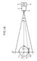
- Figs. 1A and 1B show a part of the arrangement of the embodiment, in which for simplicity of explanation, a model 1 of a simplified human face is employed as an object. Coordinates are set for the model; the coordinate axes are used as references for the irradiation positions of light beams and the positions of the image pick-up device of an optical image.
- the coordinates are set with an origin G of a bottom center of the model 1, an X-axis extending in the horizontal direction from the origin G in the front view of Fig. 1B, a Y-axis extending in the vertical direction from the origin G in the front view of Fig. 1B and a Z-axis of a vertical center line of the model 1 in the side view of Fig. 1A.
- a slit light irradiation device 90 is provided for irradiating plural slit lights 90a in order to shorten the irradiation time of the object 1.
- the slit light irradiating device 90 is constituted by plural light sources, e.g., 10 laser light generators and an optical system, e.g., cylindrical lens or concave mirror, and irradiates to the model 1 plural (e.g. 10) slit lights 90a1 - 90a10 each with a thickness of ⁇ h (e.g. 0.5 mm) and a spreading angle of ⁇ .
- the slit lights 90a1 - 90a10 each takes as a center line a perpendicular line drawn from the center of the corresponding light source to the vertical center line (Z-axis) of the model 1, and are arranged so that they are irradiated in parallel to each other and at equal intervals, e.g., 30 mm.
- An ITV camera 3 as a two-dimensional image pick-up device is arranged at a fixed distance from the slit light irradiation device 90, and so that the optical axis of the camera is directed to the model 1 and forms a predetermined angle with the slit lights 90a1 - 90a10 (For example, an angle of ⁇ is formed with the slit light 90a5).
- the effective view angle of the ITV camera 3 is ⁇
- the point where the perpendicular line drawn from the principal point of the lens of the camera to the Z-axis intersects the Z-axis is G
- the segment perpendicularly intersecting the X-axis and the Z-axis is a Y-axis
- the point G is the origin of each co-ordinate axis.
- the slit light irradiation device 90 and the ITV camera 3 are fixedly mounted on a rack 4 which is slidably guided on a guide post; the rack 4 is attached on a ball nut 6 screwed with a ball screw shaft 5.
- a step motor (not shown) connected with the ball screw shaft 5 stepwise drives the ball nut 6 up and down by the thickness ⁇ h of the slit light.
- slit light is stepwise irradiated to the model.
- plural slit light irradiation devices 90 and ITV cameras 3 associated therewith may be arranged so as to surround the model 1.
- the operation for forming the NC data on the basis of the measurement result can be simplified since the optical images corresponding to the slit lights picked up by the associated ITV cameras 3 can be directly compared.
- this is not an indispensable requisite.
- the thus obtained data with the data produced from the picking up of the above section by the respective ITV cameras 3, it is also possible to calibrate the measurement data of each camera.
- Fig. 2 shows the optical image of the slit lights 90a irradiated to the model 1 which is picked up by the ITV camera 3.
- the ITV camera 3 arranged so that the direction of its scanning lines is parallel to the plane formed by the X-axis and Z-axis, i.e., X-Z plane
- the optical images corresponding to the slit lights 90a irradiated to the model 1 are picked up by the ITV camera 3
- 10 arch slit images are provided as shown in Fig. 2
- the point P'i included in the slit image in Fig. 2 is an image of the point Pi in Figs. 1A and 1B, and corresponds to any one point of the slit light irradiated to the surface of the model 1.
- the co-ordinates y and z corresponds to the X axis and Z axis in Figs. 1A and 1B.
- S1 - S i - S r designate scanning lines of the ITV camera 3 and Ka is a threshold value for digitizing the picked-up signal into two values of brightness (high) and darkness (low).
- one image plane of the ITV camera 3 is formed by scanning the image signal from ITV camera 3 on r (generally, 250 - 500) scanning lines. These scanning lines are referred to S1, S2, S3 - S i - S r from left in accordance with the scanning order of the image signal.
- the pick-up of the optical image of the model 1 by the ITV camera 3 provides an output signal as shown in Fig. 3.
- the output signal is outputted in such a way that, as shown in Fig. 3.
- an image plane starting signal V BL (hereinafter referred to as vertical synchronizing signal) is outputted
- a first horizontal scanning starting signal (hereinafter referred to as horizontal synchronizing signal) is outputted and thereafter the image signal in accordance with the brightness or darkness of the optical image is scanned on the scanning line S1 within a fixed time ta.
- a second horizontal synchronization H BL is outputted and the image signal is scanned on the scanning line S2.
- the scanning of the image signal is repeated until the scanning line S r in the same manner.
- one image plane is accomplished.
- Fig. 4 shows a block diagram of a control circuit for acquiring the co-ordinates (xi, yi, zi) of the light spot Pi of Fig. 2, relative to the X axis, Y-axis and Z-axis, using the ITV camera 3.
- 3 is the ITV camera
- 109 is a synchronization separating circuit in which the image signal S corresponding to the optical image of the model 1 which is obtained by the irradiation of the slit light 90a and picked up by the ITV camera and is inputted together with the horizontal synchronizing signal H BL and the vertical synchronizing signal V BL is separated from H BL and V BL .
- the counter 101 designates a counter having a count input terminal (IN) coupled with the horizontal synchronizing signal H BL from the synchronization separating circuit 109 and a reset input terminal (RESET) coupled with the vertical synchronizing signal V BL .
- the counter 101 is reset to 0 by the vertical synchronizing signal V BL produced prior to the scanning of one image plane and counts the number of the horizontal synchronizing signals H BL each produced prior to the start of the scanning on each scanning line S1 - S r .
- the count of the counter 101 represents the number of the scanning line on which the video signal from the ITV camera is scanned.
- the 102 designates an oscillation circuit which continuously outputs a pulse each time interval ta/m resulting from the division of the time required to scan one scanning line into m equal parts.
- the pulses produced from the oscillator 102 are counted by a counter, which is reset to 0 by the horizontal synchronizing signal H BL .
- These pulses are counted by the counter 103 until the horizontal synchronizing signal H BL for the subsequent scanning line is produced.
- the number of the pulses counted by the counter 103 is stored in a memory circuit 107 through a gate circuit.
- digitized signal a digital signal having two values of brightness "1" and darkness "0"
- Ka Fig. 2
- This digitized signal is applied to the respective gate switching control terminals N of gate circuits 104, 105, and the gate circuits 104, 105 are closed only when the digitized signal is "1", thereby storing the contents of the counters 101, 103 into memory circuits 106, 107, respectively.
- the scanning line number content of the counter 101
- the position of a certain scanning line content of the counter 103
- plural ⁇ Yi's and ⁇ Zi's are provided for one scanning line; all of these ⁇ Yi - ⁇ Yip and ⁇ Zi - ⁇ Zip are stored in the memory circuits 106, 107. There may be the light spots of the plural slit optical images on one scanning line. Therefore, the identification of ⁇ Yi's and ⁇ Zi's is made in synchronism with the lighting commands of the slit lights 90a1 - 90a10, which are sequentially applied to the slit light irradiation device 90 from a microcomputer 110.
- ⁇ Yi and ⁇ Zi allow the X and Y co-ordinates (Xi, Yi) of the point Pi of the model 1 to be acquired in the following manner, referring to Fig. 22A.
- equations (2), (3), (4) are carried out by the microcomputer 110 and the result thereof is stored in a memory 111.
- the rack 4 as shown in Fig. 1A is driven by the step motor (not shown) by a thickness ⁇ h of the slit light in order to perform the same processing as mentioned above.
- the rack 4 is moved by the interval ⁇ h of the adjoining slit lights.
- the above explanation has been made for one measurement device including the ITV camera.
- a plurality of the ITV cameras 3 are arranged at an even distance from the Z-axis of the model 1 together with measurement processing parts associated therewith to acquire the corresponding ⁇ Yi's and ⁇ Zi's.
- the data of ⁇ Yi's and ⁇ Zi's relative to each camera are inputted into the microcomputer 110 to calculate the corresponding co-ordinates (Xi, Yi), and the result of the calculation is stored in the memory 111.
- the three-dimensional measurement of the entire periphery of the model 1 is performed.
- the plurality of ITV cameras provide plural image planes, which give rise to some overlapping between the image planes adjacent to each other.
- this overlapping can be obviated by previously setting the range of image pick-up of each ITV camera.
- the image pick-up range can be set about the optical axis of each ITV camera 3 in a range of ⁇ 360/2n relative to the Z-axis.
- all of the ITV cameras are shifted to be situated at the same level of the Z-axis.
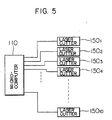
- each laser cutting machine 1501 - 15010 the above co-ordinate commands (Xi90a1, Yi90a1)1S1 - (Xi90a10, Yi90a10)1S1 are applied to the cutting machines, respectively to start the cutting of the sheets.
- the co-ordinate commands (Xi90a1, Yi90a1)1S2 - (Xi90a10, Yi90a10)lS2 are applied to the laser cutting machines 1501 - 15010, respectively, to perform the respective cuttings.
- Such an operation is repeated until the execution of the co-ordinate commands (Xi90a10, Yi90a10) 1S r .
- the NC cutting based on the co-ordinate commands (Xi90a1, Yi90a1)2S1 - (Xi90a10, Yi90a10)2Sr is performed for the ITV camera 32.
- the similar cutting is repeated until the ITV camera 3 n .
- templates each with a thickness ⁇ h having the same shape as the sectional shape of the model relative to each of the slit light planes 90a1 - 90a10.
- the processing is made at a second measurement position. The repetition of such a processing by the predetermined times of measurement provides the templates corresponding to all of the sectional shapes relative to the model.
- the stacking of the thus formed templates is done in the measurement order, e.g. a fixing using adhesive allows the model to be easily copied.
- a high speed operation processing can be realized since a plurality of slit lights are arranged so as to be irradiated to the Z-axis of the model so that the slit light sources are shifted by a short distance and the irradiation time of the slit light is reduced.
- the scanning lines of the ITV cameras are arranged in a vertical direction so that twice or more resolution in the vertical direction can be provided as compared with that in the horizontal direction, thereby improving the measurement accuracy for the model extending in the vertical direction such as a person figure.
Landscapes
- Physics & Mathematics (AREA)
- General Physics & Mathematics (AREA)
- Engineering & Computer Science (AREA)
- Automation & Control Theory (AREA)
- Length Measuring Devices By Optical Means (AREA)
Claims (3)
- Dispositif pour réaliser une copie en trois dimensions d'un objet (1) ayant une forme tridimensionnelle, comprenant:
des moyens d'irradiation (90) pour projeter sur la surface dudit objet (1) des faisceaux lumineux (90a) situés dans un plan (X-Y) prédéterminé;
des moyens capteurs d'image (3) pour capter l'image optique réfléchie par la surface dudit objet (1);
des moyens calculateurs (100, 110) pour calculer la forme de la coupe dudit objet (1) dans le plan (X-Y) du faisceau lumineux projeté (90a) sur la base des données acquises par les moyens capteurs d'image (3); et
des moyens pour déplacer à répétition lesdits moyens d'irradiation (90) d'une distance correspondant à l'épaisseur (Δh) dudit faisceau lumineux (90a), dans une direction (Z) perpendiculaire au plan (X-Y) contenant le faisceau lumineux, afin d'acquérir successivement, dans la direction (Z) dudit déplacement, les formes des coupes adjacentes respectives dudit objet (1);
dispositif dans lequel des moyens (150) sont prévus pour former, à partir d'un matériau en feuille, des gabarits ayant des formes correspondant aux coupes ainsi acquises par lesdits moyens de calcul, et pour marquer ces gabarits dans l'orientation et dans l'ordre corrects, les dimensions de chaque gabarit étant, aux dimensions de la coupe correspondante de l'objet, dans le même rapport que l'épaisseur de la feuille à l'épaisseur du faisceau lumineux,
rendant ainsi possible la réalisation d'une copie tridimensionnelle dudit objet (1), en grandeur naturelle ou proportionnée, par empilage desdits gabarits;
caractérisé
en ce que lesdits moyens d'irradiation (90) sont constitués par plusieurs sources lumineuses et projettent sur l'objet (1) plusieurs faisceaux séparés, ayant chacun une épaisseur (Δh) prédéterminée et un angle d'évasement (ϑ) prédéterminé, parallèlement les uns aux autres et à intervalles égaux,
en ce que lesdits moyens capteurs d'image (3) sont disposés à une distance fixe des moyens d'irradiation (90), de sorte que l'axe optique de la caméra forme un angle (β) prédéterminé avec l'un des faisceaux séparés (90a5),
et en ce que lesdits moyens calculateurs (100, 110) identifient les coordonnés des points (Pi) qui sont irradiés sur la surface de l'objet (1) en synchronisme avec les commandes d'allumage des faisceaux séparés (90a) qui sont appliquées successivement auxdites sources lumineuses des moyens d'irradiation (90). - Dispositif selon la revendication 1, caractérisé en ce que les moyens capteurs d'image sont constitués par une caméra de télévision industrielle (3) disposée de sorte que la direction de ses lignes de balayage soit perpendiculaire audit plan (X-Y) desdits faisceaux séparés (90a).
- Dispositif selon la revendication 1, caractérisé en ce que lesdits moyens capteurs d'image sont constitués par une caméra de télévision industrielle (3), et en ce que lesdits moyens calculateurs comprennent
un circuit de séparation (109) qui sépare le signal (S) d'image qui est capté par la caméra de télévision industrielle (3) d'avec un signal de synchronisation horizontale (HBL) et un signal de synchronisation verticale (VBL),
un premier compteur (101) comportant une borne d'entrée de comptage (IN) à laquelle est applique le signal de synchronisation horizontale (HBL) provenant du circuit de séparation (109) et une borne d'entrée de remise à l'état initial (RESET) à laquelle est appliqué le signal de synchronisation verticale (VBL), de sorte que le compte du compteur (101) représente le numéro de la ligne de balayage sur laquelle est balayé le signal d'image provenant de la caméra de télévision industrielle,
un second compteur (103) qui est remis à l'état initial par le signal de synchronisation horizontale (HBL) et qui compte les impulsions en provenance d'un circuit oscillant (102) qui délivre de façon continue une impulsion à chaque intervalle de temps (ta/m) résultant de la division en parties égales (m) du temps nécessaire pour balayer une ligne de balayage,
un premier circuit porte (104) auquel sont appliqués un signal d'image numérisé provenant de la caméra de télévision industrielle et le signal de sortie dudit premier compteur (101),
un second circuit porte (105) auquel sont appliqués le signal d'image de la caméra de télévision industrielle numérisé et le signal de sortie dudit second compteur (103), et
des première et seconde mémoires (106, 107) qui mémorisent respectivement les contenus desdits premier et second compteurs (101, 103).
Priority Applications (1)
| Application Number | Priority Date | Filing Date | Title |
|---|---|---|---|
| AT85104269T ATE69400T1 (de) | 1984-04-17 | 1985-04-09 | Einrichtung zum erzeugen einer dreidimensionalen kopie eines gegenstandes. |
Applications Claiming Priority (8)
| Application Number | Priority Date | Filing Date | Title |
|---|---|---|---|
| JP7721284A JPS60220804A (ja) | 1984-04-17 | 1984-04-17 | 立体形状作製装置 |
| JP77212/84 | 1984-04-17 | ||
| JP77213/84 | 1984-04-17 | ||
| JP59077213A JPS60220805A (ja) | 1984-04-17 | 1984-04-17 | 立体形状成形用型板製造装置 |
| JP210775/84 | 1984-10-08 | ||
| JP59210775A JPH0654228B2 (ja) | 1984-10-08 | 1984-10-08 | 立体形状の作製方法及び作製装置 |
| JP59253486A JPH068727B2 (ja) | 1984-11-30 | 1984-11-30 | 立体形状の形成方法及び形成装置 |
| JP253486/84 | 1984-11-30 |
Publications (2)
| Publication Number | Publication Date |
|---|---|
| EP0163076A1 EP0163076A1 (fr) | 1985-12-04 |
| EP0163076B1 true EP0163076B1 (fr) | 1991-11-13 |
Family
ID=27466025
Family Applications (1)
| Application Number | Title | Priority Date | Filing Date |
|---|---|---|---|
| EP85104269A Expired - Lifetime EP0163076B1 (fr) | 1984-04-17 | 1985-04-09 | Dispositif pour réaliser une copie tridimensionelle d'un objet |
Country Status (4)
| Country | Link |
|---|---|
| US (1) | US4752964A (fr) |
| EP (1) | EP0163076B1 (fr) |
| CA (1) | CA1257682A (fr) |
| DE (1) | DE3584642D1 (fr) |
Cited By (1)
| Publication number | Priority date | Publication date | Assignee | Title |
|---|---|---|---|---|
| US8036450B2 (en) | 2004-02-03 | 2011-10-11 | Paolo Bertola | Electronic photo-optical system for surveying, digitalizing and reproducing the external surface of a three-dimensional object, either virtually or in plastic, composite or papery material |
Families Citing this family (59)
| Publication number | Priority date | Publication date | Assignee | Title |
|---|---|---|---|---|
| GB8620040D0 (en) * | 1986-08-18 | 1986-10-01 | Samangooie F | Model making |
| US5085502A (en) * | 1987-04-30 | 1992-02-04 | Eastman Kodak Company | Method and apparatus for digital morie profilometry calibrated for accurate conversion of phase information into distance measurements in a plurality of directions |
| US4894551A (en) * | 1987-06-05 | 1990-01-16 | Anima Corporation | Sectional form measuring apparatus |
| JPS6446875A (en) * | 1987-08-17 | 1989-02-21 | Toshiba Corp | Object discriminating device |
| IT1211390B (it) * | 1987-10-06 | 1989-10-18 | Dea Spa | Sistema grafico interattivo per la matematizzazione di modelli fisici |
| IT212380Z2 (it) * | 1987-10-26 | 1989-07-04 | Advanced Data Processing | Macchina per il rilevamento e la matematizzazione della superficie di modelli tridimensionali partico larmente per la costruzione di stampi con macchine utensili a controllo numerico |
| FR2627047B1 (fr) * | 1988-02-09 | 1990-07-27 | Vision 3D | Procede de numerisation de la surface d'un objet tridimensionnel et appareil de releve en vue de sa mise en oeuvre |
| US4918611A (en) * | 1988-07-21 | 1990-04-17 | Industrial Technology Research Institute | Method and apparatus for controlling laser cutting by image processing |
| DE58901492D1 (de) * | 1988-10-18 | 1992-06-25 | Hasenclever Maschf Sms | Verfahren und vorrichtung zum bestimmen der geometrie eines koerpers. |
| FR2642191B1 (fr) * | 1989-01-23 | 1991-06-14 | Vision Numeric | Procede et dispositif de realisation d'un objet a partir d'une saisie tridimensionnelle de formes |
| US5121333A (en) * | 1989-06-09 | 1992-06-09 | Regents Of The University Of Minnesota | Method and apparatus for manipulating computer-based representations of objects of complex and unique geometry |
| US5184306A (en) * | 1989-06-09 | 1993-02-02 | Regents Of The University Of Minnesota | Automated high-precision fabrication of objects of complex and unique geometry |
| US5128870A (en) * | 1989-06-09 | 1992-07-07 | Regents Of The University Of Minnesota | Automated high-precision fabrication of objects of complex and unique geometry |
| US5257203A (en) * | 1989-06-09 | 1993-10-26 | Regents Of The University Of Minnesota | Method and apparatus for manipulating computer-based representations of objects of complex and unique geometry |
| US5027281A (en) * | 1989-06-09 | 1991-06-25 | Regents Of The University Of Minnesota | Method and apparatus for scanning and recording of coordinates describing three dimensional objects of complex and unique geometry |
| US5231678A (en) * | 1989-11-15 | 1993-07-27 | Ezel, Inc. | Configuration recognition system calculating a three-dimensional distance to an object by detecting cross points projected on the object |
| US5129010A (en) * | 1989-12-15 | 1992-07-07 | Kabushiki Kaisha Toyoto Chuo Kenkyusho | System for measuring shapes and dimensions of gaps and flushnesses on three dimensional surfaces of objects |
| EP0455855B1 (fr) * | 1990-05-09 | 1995-04-12 | Siemens Aktiengesellschaft | Procédé et dispositif pour fabriquer des prothèses médicales en particulier dentaires |
| EP0474458B1 (fr) * | 1990-09-04 | 2000-12-06 | Canon Kabushiki Kaisha | Appareil et méthode de modellisation tridimensionnelle |
| EP0479271B1 (fr) * | 1990-10-03 | 1998-09-09 | Aisin Seiki Kabushiki Kaisha | Système de commande de guidage latéral automatique |
| US5202742A (en) * | 1990-10-03 | 1993-04-13 | Aisin Seiki Kabushiki Kaisha | Laser radar for a vehicle lateral guidance system |
| US5390118A (en) * | 1990-10-03 | 1995-02-14 | Aisin Seiki Kabushiki Kaisha | Automatic lateral guidance control system |
| US5156777A (en) * | 1991-03-21 | 1992-10-20 | Kaye Alan H | Process for making a prosthetic implant |
| GB2254712B (en) * | 1991-04-10 | 1994-08-17 | Peter David Hurley | Individual bust |
| US5819016A (en) * | 1993-10-05 | 1998-10-06 | Kabushiki Kaisha Toshiba | Apparatus for modeling three dimensional information |
| DE59507664D1 (de) * | 1994-03-07 | 2000-03-02 | Intecu Ges Fuer Innovation Tec | Vorrichtung und Verfahren zum berührungslosen Vermessen dreidimensionaler Objekte auf der Basis optischer Triangulation |
| JP3016476U (ja) * | 1995-04-01 | 1995-10-03 | 株式会社ペティオ | 立体加工装置 |
| DE19516140A1 (de) * | 1995-05-03 | 1996-11-14 | Forschungszentrum Juelich Gmbh | Steuersystem für rastergebundene Meßdatenerfassung |
| US6141105A (en) * | 1995-11-17 | 2000-10-31 | Minolta Co., Ltd. | Three-dimensional measuring device and three-dimensional measuring method |
| US6421165B2 (en) * | 1996-02-07 | 2002-07-16 | Light & Sound Design Ltd. | Programmable light beam shape altering device using programmable micromirrors |
| US6217334B1 (en) | 1997-01-28 | 2001-04-17 | Iris Development Corporation | Dental scanning method and apparatus |
| DE19705883A1 (de) * | 1997-02-15 | 1998-08-20 | Guenter Wensing | Verfahren und Vorrichtung zum Kopieren von dreidimensionalen Gegenständen |
| US5960099A (en) * | 1997-02-25 | 1999-09-28 | Hayes, Jr.; Carl Douglas | System and method for creating a digitized likeness of persons |
| US6160910A (en) | 1998-12-02 | 2000-12-12 | Freifeld; Daniel | High precision three dimensional mapping camera |
| US6530550B1 (en) * | 2000-09-13 | 2003-03-11 | Nextengine, Inc. | Wireless turntable |
| US6579095B2 (en) | 2000-12-22 | 2003-06-17 | Geodigm Corporation | Mating parts scanning and registration methods |
| TW492558U (en) * | 2001-01-18 | 2002-06-21 | Chitai Technology Co Ltd | Passive three-dimensional taking picture control apparatus |
| US7555157B2 (en) * | 2001-09-07 | 2009-06-30 | Geoff Davidson | System and method for transforming graphical images |
| JP2003208601A (ja) * | 2002-01-15 | 2003-07-25 | Nec Corp | 3次元物体撮影装置、3次元形状モデル生成装置、3次元形状モデル生成方法、3次元形状モデル生成プログラム |
| CA2369710C (fr) * | 2002-01-30 | 2006-09-19 | Anup Basu | Methode et appareil pour le balayage 3d a haute resolution d'objets comprenant des vides |
| DE10209593B4 (de) * | 2002-03-05 | 2005-03-24 | Schott Ag | Verfahren zur Qualitätskontrolle und Schnittoptimierung von optischen Rohmaterialien |
| US20030220778A1 (en) * | 2002-04-29 | 2003-11-27 | Hultgren Bruce Willard | Method and apparatus for electronically simulating jaw function within electronic model images |
| US7716024B2 (en) * | 2002-04-29 | 2010-05-11 | Geodigm Corporation | Method and apparatus for electronically generating a color dental occlusion map within electronic model images |
| ES2324658T3 (es) | 2002-12-31 | 2009-08-12 | D4D Technologies Llc. | Sistema digitalizador por laser para aplicaciones dentales. |
| EP1606576A4 (fr) | 2003-03-24 | 2006-11-22 | D3D L P | Systeme numeriseur laser pour applications dentaires |
| JP2007528743A (ja) * | 2003-04-30 | 2007-10-18 | ディースリーディー,エル.ピー. | 口腔内画像化システム |
| AU2004237243B2 (en) * | 2003-05-05 | 2010-11-11 | D4D Technologies, Llc | Optical coherence tomography imaging |
| EP1663046A4 (fr) * | 2003-09-17 | 2011-10-05 | D4D Technologies Llc | Numerisation tridimensionnelle grande vitesse de lignes multiples |
| US7702492B2 (en) * | 2004-03-11 | 2010-04-20 | Geodigm Corporation | System and method for generating an electronic model for a dental impression having a common coordinate system |
| US7824346B2 (en) * | 2004-03-11 | 2010-11-02 | Geodigm Corporation | Determining condyle displacement utilizing electronic models of dental impressions having a common coordinate system |
| GB2414546B (en) * | 2004-05-29 | 2008-11-12 | Peter David Hurley | Apparatus and method for scanning a human face |
| US7620209B2 (en) * | 2004-10-14 | 2009-11-17 | Stevick Glen R | Method and apparatus for dynamic space-time imaging system |
| RU2285234C2 (ru) * | 2004-10-28 | 2006-10-10 | Войсковая часть 75360 | Лазерный профилометр |
| EP2801787B1 (fr) | 2011-12-27 | 2019-04-24 | Sumco Corporation | Procédé permettant de mesurer la forme tridimensionnelle d'un creuset en verre de silice, et procédé de production de silicium monocristallin |
| DE102012101302B4 (de) * | 2012-02-17 | 2014-05-15 | Kocos Optical Measurement Gmbh | Konfokaler mikroskopischer 3D-Lichtschnittsensor |
| US10210625B2 (en) * | 2015-10-30 | 2019-02-19 | Industrial Technology Research Institute | Measurement system comprising angle adjustment module |
| CN108592793B (zh) * | 2018-05-21 | 2020-11-27 | 北京智造宝科技有限公司 | 一种可扩展模块数量的人体三维扫描仪 |
| CN110908228B (zh) * | 2019-12-05 | 2022-03-18 | 歌尔股份有限公司 | 光学模组组装方法 |
| CN115905795B (zh) * | 2022-11-04 | 2025-11-11 | 浙江吉利控股集团有限公司 | 一种黄花梨树的生长参考方法、装置及介质 |
Family Cites Families (17)
| Publication number | Priority date | Publication date | Assignee | Title |
|---|---|---|---|---|
| US4041476A (en) * | 1971-07-23 | 1977-08-09 | Wyn Kelly Swainson | Method, medium and apparatus for producing three-dimensional figure product |
| DE2326289A1 (de) * | 1973-05-23 | 1974-12-19 | Sick Optik Elektronik Erwin | Automatisch gesteuerte bohrmaschine |
| DE2633036A1 (de) * | 1976-07-22 | 1978-01-26 | Wyn Kelly Swainson | Drei-dimensionale systeme |
| GB1548433A (en) * | 1976-09-30 | 1979-07-18 | Dixon K G O | Means for producing three dimensional forms from a photographic image |
| DE2834612A1 (de) * | 1978-08-07 | 1980-02-14 | Siemens Ag | Kopierfuehler |
| AT367552B (de) * | 1979-05-11 | 1982-07-12 | Chlestil Gustav Dkfm Ing | Verfahren zur fotografischen herstellung von datentraegern fuer die reproduktion dreidimensionaler objekte, vorrichtung zur durch- fuehrung des verfahrens und reproduktionseinrichtung |
| DE2936847A1 (de) * | 1979-09-12 | 1981-03-19 | Paul Dr. 6054 Rodgau Heitlinger | Verfahren zur herstellung von zahnersatz und vorrichtung zur durchfuehrung des verfahrens |
| US4473750A (en) * | 1980-07-25 | 1984-09-25 | Hitachi, Ltd. | Three-dimensional shape measuring device |
| US4404684A (en) * | 1980-07-31 | 1983-09-13 | Unitika Ltd. | Object solid figure recognizing method and apparatus |
| US4385360A (en) * | 1980-08-04 | 1983-05-24 | Micro-Power Computer Systems | Computer-controlled reproduction device |
| US4594001A (en) * | 1981-07-07 | 1986-06-10 | Robotic Vision Systems, Inc. | Detection of three-dimensional information with a projected plane of light |
| FR2521740A1 (fr) * | 1982-02-17 | 1983-08-19 | Commissariat Energie Atomique | Procede d'obtention d'images tridimensionnelles d'un objet, dispositif de mise en oeuvre de ce procede et application du procede et du dispositif a la tomographie d'un organe |
| FR2525103B1 (fr) * | 1982-04-14 | 1985-09-27 | Duret Francois | Dispositif de prise d'empreinte par des moyens optiques, notamment en vue de la realisation automatique de protheses |
| US4558420A (en) * | 1982-10-25 | 1985-12-10 | Gerber Scientific Inc. | Computer generated mold for contoured garment piece formation |
| IL67599A (en) * | 1982-12-31 | 1986-09-30 | Laser Ind Ltd | Control apparatus particularly useful for controlling a laser |
| US4596919A (en) * | 1984-08-23 | 1986-06-24 | Sri International | Three-dimensional imaging device |
| US4593967A (en) * | 1984-11-01 | 1986-06-10 | Honeywell Inc. | 3-D active vision sensor |
-
1985
- 1985-04-09 EP EP85104269A patent/EP0163076B1/fr not_active Expired - Lifetime
- 1985-04-09 US US06/721,451 patent/US4752964A/en not_active Expired - Fee Related
- 1985-04-09 DE DE8585104269T patent/DE3584642D1/de not_active Expired - Lifetime
- 1985-04-10 CA CA000478699A patent/CA1257682A/fr not_active Expired
Non-Patent Citations (1)
| Title |
|---|
| Autonation Technique, February 1981, vol 13, no 2, pages 45-49 * |
Cited By (1)
| Publication number | Priority date | Publication date | Assignee | Title |
|---|---|---|---|---|
| US8036450B2 (en) | 2004-02-03 | 2011-10-11 | Paolo Bertola | Electronic photo-optical system for surveying, digitalizing and reproducing the external surface of a three-dimensional object, either virtually or in plastic, composite or papery material |
Also Published As
| Publication number | Publication date |
|---|---|
| CA1257682A (fr) | 1989-07-18 |
| US4752964A (en) | 1988-06-21 |
| EP0163076A1 (fr) | 1985-12-04 |
| DE3584642D1 (de) | 1991-12-19 |
Similar Documents
| Publication | Publication Date | Title |
|---|---|---|
| US4752964A (en) | Method and apparatus for producing three-dimensional shape | |
| US5329597A (en) | Device and method for measuring angles of a work | |
| US8310534B2 (en) | Three-dimensional model data confirming method, and three-dimensional model data confirming apparatus | |
| US4301470A (en) | Alignment apparatus | |
| EP1043126B1 (fr) | Procédé de génération de modèle d'apprentissage | |
| US5347363A (en) | External lead shape measurement apparatus for measuring lead shape of semiconductor package by using stereoscopic vision | |
| US5402364A (en) | Three dimensional measuring apparatus | |
| EP0952488B1 (fr) | Appareil pour contrôler des masques avec temps d'inspection réduit | |
| JP2000288974A (ja) | 画像処理機能を持つロボット装置 | |
| DE3743717A1 (de) | Optoelektronische messvorrichtung zur automatischen vermessung der werkzeugschneidkantenlage mit handelsueblichen werkzeugvoreinstellgeraeten | |
| JPH06161533A (ja) | 3次元測定装置の制御方式 | |
| JP2732230B2 (ja) | レーザ光加工における同軸観測装置 | |
| JP2707548B2 (ja) | 視覚認識装置の座標補正方法 | |
| US20240127467A1 (en) | Three-dimensional shape measuring system | |
| JPH0550681B2 (fr) | ||
| JPH0654228B2 (ja) | 立体形状の作製方法及び作製装置 | |
| JPH0195889A (ja) | レーザ加工装置およびレーザ加工方法 | |
| JPH0534603B2 (fr) | ||
| JPH03259705A (ja) | 折曲機の角度計測装置 | |
| JPH03268818A (ja) | 折曲機の角度計測装置 | |
| GB2240623A (en) | An imaging process for detecting the shape of three dimensional objects | |
| JP2886223B2 (ja) | 大きな板材の加工方法及び装置 | |
| JPH05277973A (ja) | マニピュレータのキャリブレーション方法 | |
| JP2519442B2 (ja) | 工作線追従方法 | |
| CA2342969A1 (fr) | Dispositif et methode de mesure des angles d'une piece a travailler |
Legal Events
| Date | Code | Title | Description |
|---|---|---|---|
| PUAI | Public reference made under article 153(3) epc to a published international application that has entered the european phase |
Free format text: ORIGINAL CODE: 0009012 |
|
| AK | Designated contracting states |
Designated state(s): AT BE CH DE FR GB IT LI LU NL SE |
|
| 17P | Request for examination filed |
Effective date: 19851220 |
|
| 17Q | First examination report despatched |
Effective date: 19870909 |
|
| GRAA | (expected) grant |
Free format text: ORIGINAL CODE: 0009210 |
|
| AK | Designated contracting states |
Kind code of ref document: B1 Designated state(s): AT BE CH DE FR GB IT LI LU NL SE |
|
| REF | Corresponds to: |
Ref document number: 69400 Country of ref document: AT Date of ref document: 19911115 Kind code of ref document: T |
|
| REF | Corresponds to: |
Ref document number: 3584642 Country of ref document: DE Date of ref document: 19911219 |
|
| ET | Fr: translation filed | ||
| ITF | It: translation for a ep patent filed | ||
| PLBE | No opposition filed within time limit |
Free format text: ORIGINAL CODE: 0009261 |
|
| STAA | Information on the status of an ep patent application or granted ep patent |
Free format text: STATUS: NO OPPOSITION FILED WITHIN TIME LIMIT |
|
| 26N | No opposition filed | ||
| EPTA | Lu: last paid annual fee | ||
| EAL | Se: european patent in force in sweden |
Ref document number: 85104269.7 |
|
| PGFP | Annual fee paid to national office [announced via postgrant information from national office to epo] |
Ref country code: AT Payment date: 19960221 Year of fee payment: 12 |
|
| PGFP | Annual fee paid to national office [announced via postgrant information from national office to epo] |
Ref country code: LU Payment date: 19960301 Year of fee payment: 12 |
|
| PGFP | Annual fee paid to national office [announced via postgrant information from national office to epo] |
Ref country code: BE Payment date: 19960307 Year of fee payment: 12 |
|
| PGFP | Annual fee paid to national office [announced via postgrant information from national office to epo] |
Ref country code: GB Payment date: 19960401 Year of fee payment: 12 |
|
| PGFP | Annual fee paid to national office [announced via postgrant information from national office to epo] |
Ref country code: SE Payment date: 19960416 Year of fee payment: 12 |
|
| PGFP | Annual fee paid to national office [announced via postgrant information from national office to epo] |
Ref country code: NL Payment date: 19960430 Year of fee payment: 12 Ref country code: FR Payment date: 19960430 Year of fee payment: 12 |
|
| PGFP | Annual fee paid to national office [announced via postgrant information from national office to epo] |
Ref country code: CH Payment date: 19960501 Year of fee payment: 12 |
|
| PGFP | Annual fee paid to national office [announced via postgrant information from national office to epo] |
Ref country code: DE Payment date: 19960627 Year of fee payment: 12 |
|
| PG25 | Lapsed in a contracting state [announced via postgrant information from national office to epo] |
Ref country code: LU Free format text: LAPSE BECAUSE OF NON-PAYMENT OF DUE FEES Effective date: 19970409 Ref country code: GB Effective date: 19970409 Ref country code: AT Effective date: 19970409 |
|
| PG25 | Lapsed in a contracting state [announced via postgrant information from national office to epo] |
Ref country code: SE Effective date: 19970410 |
|
| PG25 | Lapsed in a contracting state [announced via postgrant information from national office to epo] |
Ref country code: LI Free format text: LAPSE BECAUSE OF NON-PAYMENT OF DUE FEES Effective date: 19970430 Ref country code: CH Free format text: LAPSE BECAUSE OF NON-PAYMENT OF DUE FEES Effective date: 19970430 Ref country code: BE Effective date: 19970430 |
|
| BERE | Be: lapsed |
Owner name: KAWASAKI JUKOGYO K.K. Effective date: 19970430 |
|
| PG25 | Lapsed in a contracting state [announced via postgrant information from national office to epo] |
Ref country code: NL Effective date: 19971101 |
|
| GBPC | Gb: european patent ceased through non-payment of renewal fee |
Effective date: 19970409 |
|
| REG | Reference to a national code |
Ref country code: CH Ref legal event code: PL |
|
| PG25 | Lapsed in a contracting state [announced via postgrant information from national office to epo] |
Ref country code: FR Free format text: LAPSE BECAUSE OF NON-PAYMENT OF DUE FEES Effective date: 19971231 |
|
| PG25 | Lapsed in a contracting state [announced via postgrant information from national office to epo] |
Ref country code: DE Free format text: LAPSE BECAUSE OF NON-PAYMENT OF DUE FEES Effective date: 19980101 |
|
| NLV4 | Nl: lapsed or anulled due to non-payment of the annual fee |
Effective date: 19971101 |
|
| EUG | Se: european patent has lapsed |
Ref document number: 85104269.7 |
|
| REG | Reference to a national code |
Ref country code: FR Ref legal event code: ST |