EP0163246A2 - Appareil de commande de moteur - Google Patents
Appareil de commande de moteur Download PDFInfo
- Publication number
- EP0163246A2 EP0163246A2 EP85106232A EP85106232A EP0163246A2 EP 0163246 A2 EP0163246 A2 EP 0163246A2 EP 85106232 A EP85106232 A EP 85106232A EP 85106232 A EP85106232 A EP 85106232A EP 0163246 A2 EP0163246 A2 EP 0163246A2
- Authority
- EP
- European Patent Office
- Prior art keywords
- engine
- intake
- heat sensitive
- sensitive element
- temperature
- Prior art date
- Legal status (The legal status is an assumption and is not a legal conclusion. Google has not performed a legal analysis and makes no representation as to the accuracy of the status listed.)
- Granted
Links
Images


Classifications
-
- F—MECHANICAL ENGINEERING; LIGHTING; HEATING; WEAPONS; BLASTING
- F02—COMBUSTION ENGINES; HOT-GAS OR COMBUSTION-PRODUCT ENGINE PLANTS
- F02D—CONTROLLING COMBUSTION ENGINES
- F02D41/00—Electrical control of supply of combustible mixture or its constituents
- F02D41/24—Electrical control of supply of combustible mixture or its constituents characterised by the use of digital means
- F02D41/2406—Electrical control of supply of combustible mixture or its constituents characterised by the use of digital means using essentially read only memories
- F02D41/2409—Addressing techniques specially adapted therefor
- F02D41/2422—Selective use of one or more tables
-
- F—MECHANICAL ENGINEERING; LIGHTING; HEATING; WEAPONS; BLASTING
- F02—COMBUSTION ENGINES; HOT-GAS OR COMBUSTION-PRODUCT ENGINE PLANTS
- F02D—CONTROLLING COMBUSTION ENGINES
- F02D41/00—Electrical control of supply of combustible mixture or its constituents
- F02D41/02—Circuit arrangements for generating control signals
- F02D41/18—Circuit arrangements for generating control signals by measuring intake air flow
- F02D41/187—Circuit arrangements for generating control signals by measuring intake air flow using a hot wire flow sensor
Definitions
- This invention relates to an engine control apparatus, and, in particular, to an electronic control device which uses a microprocessor for performing control computations of the amount of fuel to be injected by effectively using an air intake flow measurement signal.
- an engine When an engine is controlled by an electronic control device such as a microprocessor, the operating state of the engine is always monitored, the fuel injection amount in relation to the operating state of the engine is computed, and the amount of fuel is injected.
- an electronic control device such as a microprocessor
- the monitoring means for controlling the running of the engine in this way include rotation speed sensors, temperature sensors, and throttle opening sensors, etc.
- Heat-wire type intake air flow sensors are commonly used for apparatuses having this kind of purpose. These sensors are provided in the intake pipe and comprise a heat sensitive element which is heated by electricity. Namely, this heat sensistive element is heated by electricity and cooled by the flow of air in the intake pipe, the thermal variation characteristics of the element corresponding to the intake air flow.
- the electronic control unit for the engine typically comprises a microcomputer.
- the detection signals supplied to the control unit be digital. This means that the air flow measurement signal from the air flow measuring device should be digitalized.
- the air flow signal is in pulse form and the measured air flow is expressed as the pulse width of the signal.
- This kind of measurement signal can be effectively used for computations by the microcomputer by turning the air intake flow into a numerical value by the use of a clock signal to turn the pulse width into a numerical value.
- An object of this invention is to provide an engine control apparatus which can easily compute and control the fuel injection quantity, etc. in an engine control unit comprising a microcomputer on the basis of the intake conditions such as the intake air flow rate.
- Another object of this invention is to provide an engine control apparatus which can detect the air flow rate in the intake pipe of an engine and output a digital detection signal, and can effectively compute and control the fuel injection quantity, etc. in an engine control unit comprising a microcomputer, etc. based on this detection signal.
- Still another object of this invention is to provide an engine control apparatus, which supplies the measurement signal of the intake air flow rate to the microcomputer, the control program of which can simply and accurately control the engine.
- Yet another object of this invention is to be able to simply compute the air flow rate (G/N) for one engine revolution using simple means which uses a polynomial approximation, and to obtain accurate engine control data of the fuel injection amount, etc. based on this computation result, for performing engine control.
- an intake conditior measuring device used for detecting the conditions of the intake air flow rate to the engine.
- This device is constructed, for example, in the following manner.
- a heat sensitive element as the flow sensor whose resistance value varies with changes in temperature, is installed in the air intake pipe. Heating power is generated synchronously with the rotation of the engine to heat the heat sensitive element and to cut off the power supply when the element reaches a specified temperature.
- a pulse signal for expressing the length of time T that the heating power is supplied is output as the measurement signal.
- a plurality of functions which comprise the polynomial approximations of the air flow rate G/N which is an approximation obtained from the time length T and the engine speed N, are stored in a one-dimensional map as the parameters of the rotational speed N of the engine.
- the functions are read out of the one-dimensional map and the G/N calculated based on the engine speed.
- Engine control data such as the fuel injection quantity and the ignition timing are computed based on this G/N.
- the measurement output signal which indicates the time length corresponding to the air flow rate of the engine and is output from the air flow measuring apparatus, is effectively used to perform a simple computation of the fuel injection quantity.
- simple and highly accurate interpolation calculations of the G/N can be made. This has the effect of greatly simplifying the control and the control system for the engine.
- Heat sensitive element 17 the temperature of which is controlled by electricity, is located inside intake pipe 13, and is constructed of a heater, such as a platinum wire, whose resistance value varies in response to variations in temperature.
- control unit 18 which comprises a microcomputer. Power for heating is supplied to heat sensitive element 17 by command from control unit 18.
- the output signal from engine rotation speed sensor 19, the coolant temperature sensor signal (not shown), and the air/fuel ratio detection signal are supplied to engine control unit 18 indicating the running state of the engine. Based on these detection signals, the optimum fuel amount for the particular running state of the engine is calculated and a fuel injection timing signal is sent via resistors 211 to 214, respectively, to fuel injectors 201 to 204, which are provided for each cylinder.
- the supply of fuel at a constant pressure to fuel injectors 201 to 204 is set and the injection of a set amount of fuel, when the injectors are open, is controlled by an injection signal.
- the fuel is supplied from tank 23 by fuel pump 22 via fuel distributer 24.
- the pressure of the fuel is kept constant by pressure regulator 25 and the fuel amount is accurately controlled by the opening period of the injectors.
- Engine control unit 18 sends a command to igniter 26, and an ignition signal is supplied to spark plugs 281 to 28 4 via distributer 27 to control the operation of the engine by setting the ignition at a timing suitable for the particular engine conditions in response to the detection signals.
- Fig. 2 shows heat sensitive element 17 of intake air flow rate measurement apparatus 16 used in the engine control system.
- a resistance wire 172 such as a platinum wire, having certain thermal characteristics is wound around ceramic bobbin 171.
- the bobbin is supported by conductive shafts 173, 174 protruding from both ends and located on conductive pins 175, 176. Heating power is supplied to resistance wire 172 via pins 175, 176.
- the resistance wire portion is positioned in the air flow of intake pipe 13.
- Fig. 3 shows another example of heat sensitive element 17.
- Resistance wire 172 which is the heat generating body with special thermal characteristics, is formed by printing a wire on an insulative film 177, which is supported by insulative substrate 178.
- Wires 179a, 179b are formed on substrate 178, connected to resistance wire 172 for the supply of heating power.
- Fig. 4 is a circuit diagram of intake air flow rate measurement apparatus 16.
- Heat sensitive element 17 and auxiliary heat sensitive element 30 are fastened inside intake air pipe 13.
- Auxiliary element 30 also has a resistance wire such as a platinum wire, the resistance of which varies in response to the temperature of the air flow, making it a means for measuring the air temperature.
- Heat sensitive elements 17 and 30 together with fixed resistors 31 and 32 constitute a bridge circuit.
- the nodes of resistors 31 and 32, and heat sensistive elements 17 and 30, which are output terminals, are connected to the input terminals comparator 33.
- a signal is output from comparator 33.
- This output signal from comparator 33 resets flip-flop circuit 34, which is set by the start pulse signal sent from engine control unit 18 (not shown).
- the signal output from rotational speed sensor 19 synchronous with the rotation is detected by control unit 18 which then generates a start pulse also synchronous with the rotation of the engine.
- Flip-flop circuit 34 is set synchronous with the rotation of the engine and reset when the temperature of heat sensitive element 17 rises to a specified temperature. Flip-flop circuit 34 generates a pulse signal the width of which corresponds to the time between the set and reset operations. This output signal is output via buffer amplifier 35 as the output signal of the measurement apparatus.
- Transistor 36 turns the supply of power to the bridge circuit, which includes heat sensitive element 17, on and off.
- Differential amplifier 38 to which a reference voltage is supplied from reference voltage generator 37 monitors the voltage of the power supplied to the bridge circuit and controls the base potential of transistor 36. In this way the voltage value of the power sent to the bridge circuit is set at the reference value. The power sent to the bridge circuit is used for heating heat sensitive element 17.
- transistor 36 The base of transistor 36 is connected to ground via transistor 39, which is on when flip-flop circuit 34 is reset, to supply power to heat sensitive element 17.
- the start pulse signal shown in Fig. 5A is generated synchronously with the rotation of the engine, flip-flop circuit 3 4 is set corresponding to this signal and the output signal from set terminal Q rises as shown in Fig. 5B. With the rise of this signal, transistor 36 is turned on and power is supplied to heat sensitive element 17. When this constant voltage power is supplied, heat sensitive element 17 heats up and the temperature rises as shown in Fig. 5C. In this case, the temperature rise velocity is determined by the cooling effect of the air flow on heat sensitive element 17; the greater the air flow, the slower temperature rise velocity, and the smaller the flow, the greater the velocity.
- the resistance value also increases so the voltage at node a drops lower than the voltage at node b, and the output signal from comparator 35 rises. Namely, when the temperature of heat sensitive element 17 rises to a set temperature difference over the air temperature as measured by auxiliary heat sensitive element 30, the signal from comparator 33 rises as shown in Fig. 5D and resets flip-flop circuit 34 turning off transistor 36 so that power to element 17 is turned off.
- the start pulse signal After the start pulse signal has caused the heating power to the heat sensitive element -17 to rise, the power supply is continued during the time period until element 17 reaches a specified temperature.
- This signal corresponding to this time period, is output from flip-flop circuit 34. Because the temperature rise velocity of element 17 corresponds to the air flow rate in intake pipe 13, the time length of the setting of flip-flop circuit 34 indicates the air flow rate.
- the output signal of flip-flop circuit 34 as shown in Fig. 5B, is the measurement signal of the air flow rate in intake pipe 13, and is expressed by time length T and cycle T N . This signal is supplied to engine control unit 18 to be used in the computation of the fuel injection amount.
- the pulse width T of this measurement signal which corresponds to the measured air flow rate, can be expressed as follows.
- the air flow rate G/N corresponding to the number of engine rotation is determined, and engine control unit 18 then determines the fuel injection time length corresponding to the fuel injection amount.
- the microcomputer control program for calculating G/N is extremely complicated.
- the following is a simple means for accurately calculating the intake air flow rate per engine rotation G/N.
- equation (1) for G/N is changed to the following theoretical equation: G/N ⁇ N(T- ⁇ /N) 2 / ⁇ 2 ....(2)
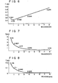
- Figs. 6 to 8 show experimental data representing the relationship between the above functions and engine rotation number of a 4-cylindered engine.
- the contents of Figs. 6 to 8 are stored in the memory device as a one-dimensional map.
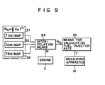
- functions f l (N), f 2 ( N ) 7 f 3 ( N ) of equation (3) are stored in function memory devices 51-53 as maps of the parameters of the number of engine rotations N shown in Figs. 6-8, corresponding to these functions.
- Interpolation calculation means 54 reads out these maps in response to the number engine rotations N.
- G/N which obtained based on these read out functions, is supplied to the fuel injection ratio calculation means 55 and the fuel injection ratio is calculated corresponding to time data T of the output signal from air flow rate measurement apparatus 16, corresponding to the measured air flow rate.
- Fig. 10 is the base processing of the main control routine of engine control unit 18.
- the device is reset, and, in step 101 initialization is executed.
- analog detection of the engine operating state such as coolant temperature, air temperature, exhaust gas oxide content and battery voltage, etc. is performed, and this data is A/D converted and supplied as digital data in step 102.
- step 103 various correction amounts corresponding to these detection signals are calculated and used in the correction calculatios of the fuel injection time length, for example.
- Fig. 11 is a flow chart for the means for determining the amount of fuel, in actuality, the fuel injection time length, in response to the operating state of the engine. This calculation routine is interrupted in response to the signal that is synchronous with the rotation of the engine, i.e., ignition signal IG.
- step 201 the count value tl of the counter, which operates in the free state, is read out in response to signal IG and is compared to count value tl' read out in response to the previous signal IG. That is, a count value corresponding to the IG signal generation interval is calculated and the number of rotations of the engine detected.
- step 202 based on the number of rotations N detected in step 201, functions f l (N), f 2 ( N ), f 3 ( N ), such as those shown in Figs. 6 to 8, from map memory device 51-53 are interpolated and, in step 203, the fuel injection timing t3 is set.
- Air flow rate measurement apparatus 16 controls the rise of the heating power to element 17 by applying a start pulse signal generated at timing tl corresponding to signal IG.
- step 204 timing t4 of the drop of the pulse output signal from measurement apparatus 16 is detected and the time length T corresponding to the air flow rate measurement value is calculated (t4-tl).
- T A the injection time length
- T B the injection finish time to t5 is set in step 207.
- equation (2) which expresses the air flow rate G/N per engine rotation, is used to obtain a 2-dimensional map of the time length T and the number of rotations N, it is necessary to divide the point by 50 to obtain the error range of ⁇ 2 % for the time length T and number of rotations N required to ensure the required accuracy. Consequently, there are many map setting points and many points that are not used, which is very uneconomical.
- air flow rate measurement apparatus 16 supplies heat power to heat sensistive element 17 at a constant voltage setting. It is, however, possible to supply the heating power at a constant current, instead. Namely, a constant current heating power is supplied to heat sensitive element 17 whose temperature increases at a velocity corresponding to the measured air flow rate. When element 17 reaches a specified temperature, this is detected. By this detection operation it is possible to obtain a measurement output signal for pulse time width T, the same as with the previous embodiment.
- the intake condition measuring device detects the intake air flow rate, and based on this air flow rate G/N the injection quantity of fuel is calculated.
- the intake condition measuring device may be adapted to detect the intake air pipe pressure P.
Landscapes
- Engineering & Computer Science (AREA)
- Chemical & Material Sciences (AREA)
- Combustion & Propulsion (AREA)
- Mechanical Engineering (AREA)
- General Engineering & Computer Science (AREA)
- Combined Controls Of Internal Combustion Engines (AREA)
- Measuring Volume Flow (AREA)
- Electrical Control Of Air Or Fuel Supplied To Internal-Combustion Engine (AREA)
Applications Claiming Priority (2)
| Application Number | Priority Date | Filing Date | Title |
|---|---|---|---|
| JP59107783A JPS60252139A (ja) | 1984-05-28 | 1984-05-28 | エンジンの制御装置 |
| JP107783/84 | 1984-05-28 |
Publications (3)
| Publication Number | Publication Date |
|---|---|
| EP0163246A2 true EP0163246A2 (fr) | 1985-12-04 |
| EP0163246A3 EP0163246A3 (en) | 1986-02-12 |
| EP0163246B1 EP0163246B1 (fr) | 1988-07-27 |
Family
ID=14467905
Family Applications (1)
| Application Number | Title | Priority Date | Filing Date |
|---|---|---|---|
| EP85106232A Expired EP0163246B1 (fr) | 1984-05-28 | 1985-05-21 | Appareil de commande de moteur |
Country Status (4)
| Country | Link |
|---|---|
| US (1) | US4730255A (fr) |
| EP (1) | EP0163246B1 (fr) |
| JP (1) | JPS60252139A (fr) |
| DE (1) | DE3564007D1 (fr) |
Cited By (6)
| Publication number | Priority date | Publication date | Assignee | Title |
|---|---|---|---|---|
| GB2194652A (en) * | 1986-09-01 | 1988-03-09 | Hitachi Ltd | A method of and apparatus for fuel control |
| GB2213290A (en) * | 1987-12-28 | 1989-08-09 | Fuji Heavy Ind Ltd | Fuel injection control system for i/c engine |
| AU608253B2 (en) * | 1986-12-01 | 1991-03-28 | Woodward Governor Company | Method and apparatus for iterated determinations of sensed speed and speed governing |
| WO1991010821A1 (fr) * | 1990-01-19 | 1991-07-25 | Siemens Aktiengesellschaft | Systeme de commande de moteur a flux d'air massique avec integrateur d'impulsions d'air massique |
| EP0420442A3 (en) * | 1989-09-19 | 1992-03-04 | General Motors Corporation | Method and apparatus for determining air mass in an engine |
| RU2647878C2 (ru) * | 2012-09-21 | 2018-03-21 | Континенталь Отомотив Франс | Способ оценки скорости вращения двигателя в заданном положении |
Families Citing this family (9)
| Publication number | Priority date | Publication date | Assignee | Title |
|---|---|---|---|---|
| JPS6223557A (ja) * | 1985-07-24 | 1987-01-31 | Hitachi Ltd | 内燃機関の学習制御方法 |
| JPS6461611A (en) * | 1987-09-02 | 1989-03-08 | Hitachi Ltd | Air flow rate sensor |
| JPH0760107B2 (ja) * | 1989-07-11 | 1995-06-28 | 三菱電機株式会社 | 熱式流量センサの信号処理方法 |
| US5136517A (en) * | 1990-09-12 | 1992-08-04 | Ford Motor Company | Method and apparatus for inferring barometric pressure surrounding an internal combustion engine |
| US6557531B2 (en) * | 1996-09-13 | 2003-05-06 | Hitachi, Ltd. | Thermal type air flow meter |
| US6866027B1 (en) | 2003-09-17 | 2005-03-15 | Walbro Engine Management, L.L.C. | Throttle body assembly for a fuel injected combustion engine |
| WO2005049996A1 (fr) * | 2003-11-18 | 2005-06-02 | Mack Trucks, Inc. | Systeme et procede de regulation pour augmenter les economies de carburant |
| FR2942849B1 (fr) * | 2009-03-03 | 2011-04-01 | Renault Sas | Procede de traitement d'un signal issu d'un debitmetre de mesure d'un debit de gaz dans un moteur a combustion interne |
| DE102009059931A1 (de) * | 2009-12-22 | 2011-06-30 | Volkswagen AG, 38440 | Ermitteln und Parametrieren von Polynom-Modellen für Verbrennungsmotoren |
Family Cites Families (15)
| Publication number | Priority date | Publication date | Assignee | Title |
|---|---|---|---|---|
| GB1052172A (fr) * | 1963-02-05 | 1900-01-01 | ||
| FR2355437A6 (fr) * | 1972-05-10 | 1978-01-13 | Peugeot & Renault | Systeme de commande du type analogique-numerique-analogique a calculateur digital a fonctions multiples pour vehicule automobile |
| DE2448304C2 (de) * | 1974-10-10 | 1986-04-03 | Robert Bosch Gmbh, 7000 Stuttgart | Elektrisch gesteuerte Kraftstoffeinspritzanlage für Brennkraftmaschinen |
| JPS535335A (en) * | 1976-07-05 | 1978-01-18 | Nippon Soken Inc | Suction air quantity detector for internal combustion engine |
| JPS6047462B2 (ja) * | 1978-06-02 | 1985-10-22 | 株式会社日立製作所 | 電子制御燃料噴射装置の吸入空気量計測装置 |
| US4304129A (en) * | 1978-11-13 | 1981-12-08 | Nippon Soken, Inc. | Gas flow measuring apparatus |
| JPS55104538A (en) * | 1979-02-05 | 1980-08-11 | Hitachi Ltd | Air-fuel ratio controlling system for internal combustion engine |
| JPS5651618A (en) * | 1979-10-03 | 1981-05-09 | Hitachi Ltd | Hot-wire flow sensor circuit |
| JPS5688138A (en) * | 1979-12-21 | 1981-07-17 | Dainippon Screen Mfg Co Ltd | Forming method of memory table |
| JPS5692330A (en) * | 1979-12-25 | 1981-07-27 | Hitachi Ltd | Signal processing method for hot wire flow sensor |
| JPS56143915A (en) * | 1980-04-11 | 1981-11-10 | Nippon Soken Inc | Measuring device for gas flow rate |
| JPS572436A (en) * | 1980-06-06 | 1982-01-07 | Japan Electronic Control Syst Co Ltd | Electronically controlled fuel injection device |
| JPS5710415A (en) * | 1980-06-23 | 1982-01-20 | Isuzu Motors Ltd | Measuring method for suction amount |
| JPS5756632A (en) * | 1980-09-19 | 1982-04-05 | Hitachi Ltd | Fuel control method |
| JPS5895214A (ja) * | 1981-12-02 | 1983-06-06 | Hitachi Ltd | 熱線式流量センサの信号処理方法 |
-
1984
- 1984-05-28 JP JP59107783A patent/JPS60252139A/ja active Granted
-
1985
- 1985-05-21 EP EP85106232A patent/EP0163246B1/fr not_active Expired
- 1985-05-21 DE DE8585106232T patent/DE3564007D1/de not_active Expired
- 1985-05-23 US US06/737,088 patent/US4730255A/en not_active Expired - Fee Related
Cited By (9)
| Publication number | Priority date | Publication date | Assignee | Title |
|---|---|---|---|---|
| GB2194652A (en) * | 1986-09-01 | 1988-03-09 | Hitachi Ltd | A method of and apparatus for fuel control |
| GB2194652B (en) * | 1986-09-01 | 1991-02-13 | Hitachi Ltd | A method of and apparatus for fuel control |
| AU608253B2 (en) * | 1986-12-01 | 1991-03-28 | Woodward Governor Company | Method and apparatus for iterated determinations of sensed speed and speed governing |
| GB2213290A (en) * | 1987-12-28 | 1989-08-09 | Fuji Heavy Ind Ltd | Fuel injection control system for i/c engine |
| GB2213290B (en) * | 1987-12-28 | 1992-08-19 | Fuji Heavy Ind Ltd | Fuel injection control system for an automotive engine |
| EP0420442A3 (en) * | 1989-09-19 | 1992-03-04 | General Motors Corporation | Method and apparatus for determining air mass in an engine |
| WO1991010821A1 (fr) * | 1990-01-19 | 1991-07-25 | Siemens Aktiengesellschaft | Systeme de commande de moteur a flux d'air massique avec integrateur d'impulsions d'air massique |
| RU2647878C2 (ru) * | 2012-09-21 | 2018-03-21 | Континенталь Отомотив Франс | Способ оценки скорости вращения двигателя в заданном положении |
| US10041966B2 (en) | 2012-09-21 | 2018-08-07 | Continental Automotive France | Method for estimating the speed of an engine in a predefined position |
Also Published As
| Publication number | Publication date |
|---|---|
| DE3564007D1 (en) | 1988-09-01 |
| JPS60252139A (ja) | 1985-12-12 |
| EP0163246A3 (en) | 1986-02-12 |
| US4730255A (en) | 1988-03-08 |
| EP0163246B1 (fr) | 1988-07-27 |
| JPH0578667B2 (fr) | 1993-10-29 |
Similar Documents
| Publication | Publication Date | Title |
|---|---|---|
| EP0163246A2 (fr) | Appareil de commande de moteur | |
| EP0212076B1 (fr) | Appareil pour le contôle d'un moteur | |
| US4578996A (en) | Gas-flow measuring apparatus and method | |
| US4649745A (en) | Apparatus for measuring a flow rate of intake air for an engine | |
| US4565091A (en) | Apparatus for measuring the quantity of airflow passing through an intake passage of an engine | |
| US4671242A (en) | Engine control apparatus | |
| EP0164729B1 (fr) | Système de commande de moteur | |
| US4688425A (en) | Direct-heated flow measuring apparatus having film resistor | |
| US4596138A (en) | Measuring apparatus for internal combustion engine | |
| JP2524847B2 (ja) | 熱式吸入空気量センサ | |
| EP0180130B1 (fr) | Système de commande pour moteur ayant un passage d'air | |
| JPS6345508A (ja) | エンジンの吸入空気量測定装置 | |
| JP2510151B2 (ja) | エンジン用熱式空気流量測定装置 | |
| JP2502570B2 (ja) | エンジン制御装置 | |
| JPH0548402B2 (fr) | ||
| JPH0646164B2 (ja) | 内燃機関の制御に用いられる空気流量検出装置 | |
| JPS63111262A (ja) | エンジン制御装置 | |
| JPH09158758A (ja) | 内燃機関の制御装置 | |
| JPS6390640A (ja) | 内燃機関用燃料供給量制御装置 | |
| JPH0646165B2 (ja) | エンジン制御装置に用いられる空気流量検出装置 | |
| JPS60247029A (ja) | エンジンの制御装置 | |
| JPS6263159A (ja) | 内燃機関の制御装置 | |
| JPH05281008A (ja) | 空気流量計 | |
| JPH0668450B2 (ja) | 内燃機関の制御に用いられる空気流量検出装置 | |
| JPH0654247B2 (ja) | 内燃機関の制御に用いられる空気流量検出装置 |
Legal Events
| Date | Code | Title | Description |
|---|---|---|---|
| PUAI | Public reference made under article 153(3) epc to a published international application that has entered the european phase |
Free format text: ORIGINAL CODE: 0009012 |
|
| AK | Designated contracting states |
Designated state(s): DE FR GB |
|
| PUAL | Search report despatched |
Free format text: ORIGINAL CODE: 0009013 |
|
| AK | Designated contracting states |
Designated state(s): DE FR GB |
|
| 17P | Request for examination filed |
Effective date: 19860305 |
|
| 17Q | First examination report despatched |
Effective date: 19870211 |
|
| GRAA | (expected) grant |
Free format text: ORIGINAL CODE: 0009210 |
|
| AK | Designated contracting states |
Kind code of ref document: B1 Designated state(s): DE FR GB |
|
| REF | Corresponds to: |
Ref document number: 3564007 Country of ref document: DE Date of ref document: 19880901 |
|
| ET | Fr: translation filed | ||
| PLBE | No opposition filed within time limit |
Free format text: ORIGINAL CODE: 0009261 |
|
| STAA | Information on the status of an ep patent application or granted ep patent |
Free format text: STATUS: NO OPPOSITION FILED WITHIN TIME LIMIT |
|
| 26N | No opposition filed | ||
| PGFP | Annual fee paid to national office [announced via postgrant information from national office to epo] |
Ref country code: FR Payment date: 19960510 Year of fee payment: 12 |
|
| PGFP | Annual fee paid to national office [announced via postgrant information from national office to epo] |
Ref country code: GB Payment date: 19960513 Year of fee payment: 12 |
|
| PGFP | Annual fee paid to national office [announced via postgrant information from national office to epo] |
Ref country code: DE Payment date: 19960528 Year of fee payment: 12 |
|
| PG25 | Lapsed in a contracting state [announced via postgrant information from national office to epo] |
Ref country code: GB Effective date: 19970521 |
|
| GBPC | Gb: european patent ceased through non-payment of renewal fee |
Effective date: 19970521 |
|
| PG25 | Lapsed in a contracting state [announced via postgrant information from national office to epo] |
Ref country code: FR Free format text: LAPSE BECAUSE OF NON-PAYMENT OF DUE FEES Effective date: 19980130 |
|
| PG25 | Lapsed in a contracting state [announced via postgrant information from national office to epo] |
Ref country code: DE Free format text: LAPSE BECAUSE OF NON-PAYMENT OF DUE FEES Effective date: 19980203 |
|
| REG | Reference to a national code |
Ref country code: FR Ref legal event code: ST |