EP0163263A2 - Dispositif pour la manipulation du papier dans une imprimante - Google Patents
Dispositif pour la manipulation du papier dans une imprimante Download PDFInfo
- Publication number
- EP0163263A2 EP0163263A2 EP85106349A EP85106349A EP0163263A2 EP 0163263 A2 EP0163263 A2 EP 0163263A2 EP 85106349 A EP85106349 A EP 85106349A EP 85106349 A EP85106349 A EP 85106349A EP 0163263 A2 EP0163263 A2 EP 0163263A2
- Authority
- EP
- European Patent Office
- Prior art keywords
- paper
- roller
- transfer
- transfer roller
- drive mechanism
- Prior art date
- Legal status (The legal status is an assumption and is not a legal conclusion. Google has not performed a legal analysis and makes no representation as to the accuracy of the status listed.)
- Withdrawn
Links
Images

Classifications
-
- B—PERFORMING OPERATIONS; TRANSPORTING
- B41—PRINTING; LINING MACHINES; TYPEWRITERS; STAMPS
- B41J—TYPEWRITERS; SELECTIVE PRINTING MECHANISMS, i.e. MECHANISMS PRINTING OTHERWISE THAN FROM A FORME; CORRECTION OF TYPOGRAPHICAL ERRORS
- B41J13/00—Devices or arrangements of selective printing mechanisms, e.g. ink-jet printers or thermal printers, specially adapted for supporting or handling copy material in short lengths, e.g. sheets
- B41J13/10—Sheet holders, retainers, movable guides, or stationary guides
- B41J13/103—Sheet holders, retainers, movable guides, or stationary guides for the sheet feeding section
Definitions
- This invention generally relates to an apparatus for handling paper in a printer and more particularly relates to an apparatus for handling paper in a printer having an image transfer drum.
- ink jet printers a stream of ink is directed at a medium to produce a pattern corresponding to the information to be printed.
- a stream of ink is directed at a medium to produce a pattern corresponding to the information to be printed.
- One such printer is described in copending U.S. Patent Application No. 497,386 entitled “Ink Jet Printer” filed May 23, 1983, by D. B. Durkee et. al. and having a common assignee with this application.
- ink droplets are directed at the surface of a rotating transfer drum.
- the ink pattern deposited upon the drum is transferred to a sheet of paper which is brought into contact with the surface of the drum.
- the paper handling mechanism used in such printers must meet certain criteria. As described in the aforementioned application, the paper must initially contact the drum at a predetermined location to assure accurate positioning of the information on the paper.
- This invention relates to an apparatus for transporting single sheets of paper from a paper supply station into surface contact with a transfer drum and thereafter to a receiving station.
- the transfer drum has deposited thereon an ink pattern corresponding to the indicia to be printed.
- a selectively driven feed roller is in contact with a sheet of paper at a paper supply station and directs the sheet of paper toward a paper drive mechanism.
- the paper drive mechanism has a rest position and a transfer position whereat an image is transferred from the transfer drum to the sheet-of paper.
- the paper drive mechanism includes a transfer roller coupled to a paper alignment roller by a drive belt.
- the transfer roller and drive belt define a paper path therebetween.
- the paper handling apparatus also includes means for selectively moving the paper drive mechanism from the rest position to the transfer position whereat a sheet of paper is pressed against the transfer drum by the indicia transfer roller and directed through the paper drive mechanism by the drive belt.
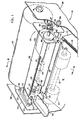
- the printer 10, illustrated in FIG. 1, includes a paper supply station in the form of a storage tray 12.
- the tray 12 includes a platform 14 (FIG. 4) which is biased upwardly by a spring 15 forcing the top sheet 16 of a paper stack 18 against a stripping roller 20 supported on an axle 21 rotatably driven in the direction of the arrow 23.
- the outer surface of the roller 20 is coated with an easily deformable material providing high frictional coupling with the sheet of paper 16.
- the top of the paper stack 18 is pushed at its forward edge against a pair of stripping fingers 22.
- the fingers 22 provide sufficient resistance to the movement of the top sheet of paper 16 so that only a single sheet of paper will be moved from the stack at a time.
- the paper sheet 16 is deflected by a pair of guide plates 24, 25 to a position with the leading edge thereof forced against the nip of a segmented pressure roller 26 having an axle 27 and a transfer roller 28" having an axle 29 forming component parts of a drive mechanism 30.
- the stripping roller 20 continues to advance the paper sheet 16 until a bow is formed.
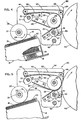
- the curl of the sheet 16 supplies the force necessary to maintain the sheet 16 against the nip of the rollers 26, 28 as illustrated in FIG. 5.
- the drive mechanism 30 includes a pair of spacially positioned end plates 32, 34 supported for rotation about a pivot rod 36 fixed to the frame of the printer 38.
- the pivot rod 36 is parallel to the axle 41 of rotation of an image transfer drum 40.
- the ends of the pressure roller shaft 27 are positioned through two elongated holes 43 in the end plates 32, 34.
- mounted to the facing surfaces of the end plates 32, 34 are three spacially positioned guide rollers 42, 44, 46 about which a belt 50 is placed.
- the guide rollers 42, 44, 46 define an "L" shaped belt path with the rollers 26, 28 located within the acute angle defined by the "L" shaped belt path.
- the belt 50 passes over a small segment 51 of the pressure roller 26 and around the transfer roller 28 so that as the belt 50 moves, the rollers 26, 28 rotate in opposite directions.
- the relatively small diameter of the roller segment 51 as compared to diameter of the segments 26 assumes that the rollers 26 and 28 will remain in contact without interference from the belt 50.
- the sheet of paper 16 fed from the supply stack 18 will advance between the transfer roller 28 and the belt 50. Under guidance from the belt 50, the paper will move along a discharge shelf 52 to a-receiving station in .the form of a shelf 54.
- each end of the pressure roller shaft 27 passes through an elongated hole 44 in the end plates 32, 34. Also, each end of the shaft 27 is cut with a groove which receives one end of a coil spring 56. The opposite ends of the coil springs 56 are secured to support studs 58 mounted upon the outwardly disposed surfaces of the drive plates 32, 34. The springs 56 urge the roller 26 toward the transfer roller 28 thereby assuring contact between the .two rollers. Additionally, located at the outwardly disposed surface of the end plates 32, 34 are coil springs 60 attached between respective stud pairs 62, 64. The stud 62 is fixed to the end plate and the stud 63 to the frame 38 of the printer 10 (FIG. 3).
- the coil springs 60 bias the paper mechanism 30 in a clockwise direction around the pivot rod 36 thus urging the transfer roller 28 toward the surface of the transfer drum 40.
- the drive mechanism 30 is positioned about the pivot rod I 36 against the bias of the spring 60'by a pair of rotary cams 66, 68 mounted upon the ends of a cam shaft 70 supported by the frame 38 and passing through enlarged holes 71 in the end plates 32, 34.
- the cams 66, 68 respectively engage cam followers in the form of a roller bearing 72, 74 mounted on the outwardly disposed surfaces of the side plates 32, 34.
- the paper drive mechanism 30 rotates about the support rod 36 against the bias of the coil springs 60.
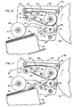
- the cams 66, 68 rotate the paper feed mechanism 30 about the support rod 36 between a paper loading position (FIG. 4) and a print position (FIG. 7).
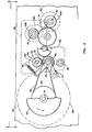
- a motor (not shown) is coupled to a drive gear 80 mounted upon n transfer drum shaft 81 and a drive pulley 82 is also mounted upon the drum shaft 81.
- a support shaft 83 carries a driven pulley 86 as well as two gears 90, 92.
- the two pulleys 82, 86 are coupled by a belt 89.
- a belt tensioning assembly 94 maintains the belt 89 tension as the drive mechanism rotates about the support rod 36 between the drive and print pori- tions.
- the driven gear 92 is coupled to a transfer roller gear 100 through an overrunning electrically operated clutch 101.
- the shaft of the transfer roller is positioned through oversized holes 103 in the end plates 32, 34 to allow movement of gear 100 about the driven gear 92 as the paper drive mechanism 30 rotates on the support rod 36.
- the gear 90 is coupled through a reducing idler gear assembly 102 mounted to the frame 38 of the printer 10, and the output of the idler gear assembly 102 engages a stripping roller gear 104 and a cam gear 106.
- the stripping roller gear 104 is coupled through a selectively operable overrunning electrical clutch 108 to the stripping roller axle 21, and the cam gear 106 is coupled through an electrically operable clutch 109 to the cam shaft 70.
- FIGS. 4, 5, 6, and 7. The operational sequence of the paper feed mechanism 30 is illustrated in FIGS. 4, 5, 6, and 7.
- the stripping roller clutch 108 is actuated and the roller 20 drives the sheet of paper 16 forward causing it to buckle under the restraining influence of the stripping fingers 22.
- the paper snaps away from the restraining fingers 22, is deflected by the plates 24, 25 into the position illustrated in FIG. 5.
- the forward edge of the paper is now forced against the nip of the rollers 26, 28. In this position, the rise of the cams 66 and 68 are adjacent their respective followers 72, 74; n nd the transfer roller 28 is withdrawn from the transfer drum 40.
- Ink is discharged onto the rotating transfer drum 40 in accordance with the image to be printed as described in the aforementioned copending patent application.
- the transfer roller clutch 108 is energized, and the transfer roller 28 rotates.
- the stripping roller 20 and transfer roller 28 are mounted on their respective axles 21, 29 by overrunning clutches 101, 108.
- the overrunning clutch 108 the stripping roller does not drive the paper 16 after the transfer roller 28 engages the paper since the drive speed of the transfer roller 28 is greater than thnt of the stripping roller 20.
- the cam clutch 109 is energized; and the cams 66, 68 rotate until the falls are adjacent to their respective followers 72, 74 forcing the transfer roller 28 against the rotating transfer drum 40 by bias springs 60 as illustrated in FIG. 6.
- the drum drives the trans- fer roller at a greater rotational speed than the gear 92 (FIG. 3) and the overrunning clutch 101 releases allowing the roller 28 to be freely driven by the drum 40.
- the transfer roller 28 advances the belt 50 causing the paper 16 to advance between the belt 50 and the transfer roller 28 and out along the discharge shelf 52.
- the start of the image deposited on the transfer drum 40 is indicated by the arrow designated P.S. (Print Start).
- Energization of the cam clutch 108 is in synchronization with the rotation of the transfer drum NO that the paper will contact the transfer drum at the desired location for proper orientation of the printing on the paper 16. After the image is transferred to the paper 16, the paper 16 is discharged along the discharge shelf 52 storage shell 54.
Landscapes
- Delivering By Means Of Belts And Rollers (AREA)
- Separation, Sorting, Adjustment, Or Bending Of Sheets To Be Conveyed (AREA)
Applications Claiming Priority (2)
| Application Number | Priority Date | Filing Date | Title |
|---|---|---|---|
| US616028 | 1984-06-01 | ||
| US06/616,028 US4600929A (en) | 1984-06-01 | 1984-06-01 | Apparatus for handling paper in a printer |
Publications (2)
| Publication Number | Publication Date |
|---|---|
| EP0163263A2 true EP0163263A2 (fr) | 1985-12-04 |
| EP0163263A3 EP0163263A3 (fr) | 1988-05-11 |
Family
ID=24467765
Family Applications (1)
| Application Number | Title | Priority Date | Filing Date |
|---|---|---|---|
| EP85106349A Withdrawn EP0163263A3 (fr) | 1984-06-01 | 1985-05-23 | Dispositif pour la manipulation du papier dans une imprimante |
Country Status (3)
| Country | Link |
|---|---|
| US (1) | US4600929A (fr) |
| EP (1) | EP0163263A3 (fr) |
| CA (1) | CA1242223A (fr) |
Cited By (2)
| Publication number | Priority date | Publication date | Assignee | Title |
|---|---|---|---|---|
| US5033891A (en) * | 1988-08-17 | 1991-07-23 | Daiwa Seiko, Inc. | Printing machine |
| EP0464785A3 (en) * | 1990-07-04 | 1992-03-04 | Canon Kabushiki Kaisha | Sheet feeding apparatus |
Families Citing this family (13)
| Publication number | Priority date | Publication date | Assignee | Title |
|---|---|---|---|---|
| JPS6388861U (fr) * | 1986-11-27 | 1988-06-09 | ||
| US4761664A (en) * | 1987-03-02 | 1988-08-02 | Eastman Kodak Company | Print media handling system for compact printer with traversing, multiple print head carriage |
| US4918463A (en) * | 1987-03-02 | 1990-04-17 | Eastman Kodak Company | Compact printer having an integral cut-sheet feeder |
| US4763138A (en) * | 1987-03-02 | 1988-08-09 | Eastman Kodak Company | Compact printer having an integral cut-sheet feeder |
| JPH02238469A (ja) * | 1989-03-10 | 1990-09-20 | Canon Inc | 画像形成装置 |
| JPH04313528A (ja) * | 1990-07-24 | 1992-11-05 | Canon Inc | 自動給紙装置 |
| EP0508572B1 (fr) * | 1991-02-22 | 1995-08-16 | Kabushiki Kaisha Toshiba | Appareil d'alimentation de matériaux en feuille |
| JPH083397Y2 (ja) * | 1991-05-24 | 1996-01-31 | 株式会社精工舎 | 給紙カセット |
| JP3098369B2 (ja) * | 1993-12-15 | 2000-10-16 | キヤノン株式会社 | シート給送装置及び記録装置 |
| US6817611B2 (en) | 2002-05-22 | 2004-11-16 | Agfa Corporation | Nip mechanism and method of operation thereof |
| US6695503B1 (en) | 2002-10-02 | 2004-02-24 | Lexmark International, Inc. | Print media feed system for an imaging apparatus |
| US7780161B2 (en) * | 2005-12-05 | 2010-08-24 | Silverbrook Research Pty Ltd | Method of picking media in printer |
| JP4516542B2 (ja) * | 2006-03-30 | 2010-08-04 | 株式会社東芝 | 画像形成装置および用紙搬送装置 |
Family Cites Families (8)
| Publication number | Priority date | Publication date | Assignee | Title |
|---|---|---|---|---|
| US3770345A (en) * | 1969-03-21 | 1973-11-06 | Canon Kk | Electrophotographic copying apparatus |
| US3652083A (en) * | 1969-10-31 | 1972-03-28 | John Benton Inc | Paper feed mechanism |
| US3642271A (en) * | 1970-05-27 | 1972-02-15 | Bridge Data Products Inc | Card feeder |
| GB1598121A (en) * | 1977-03-18 | 1981-09-16 | Ricoh Kk | Sheet processing apparatus |
| NL185691C (nl) * | 1977-08-29 | 1990-06-18 | Oce Van Der Grinten Nv | Kopieerapparaat. |
| US4302093A (en) * | 1979-10-17 | 1981-11-24 | Savin Corporation | Combined transfer and registration system for electrophotographic copier |
| US4354759A (en) * | 1981-05-01 | 1982-10-19 | Pitney Bowes Inc. | Copy paper feed mechanism |
| US4475732A (en) * | 1982-09-21 | 1984-10-09 | Xerox Corporation | Sheet feeding and separating apparatus with stack force relief/enhancement |
-
1984
- 1984-06-01 US US06/616,028 patent/US4600929A/en not_active Expired - Lifetime
-
1985
- 1985-03-29 CA CA000477982A patent/CA1242223A/fr not_active Expired
- 1985-05-23 EP EP85106349A patent/EP0163263A3/fr not_active Withdrawn
Cited By (3)
| Publication number | Priority date | Publication date | Assignee | Title |
|---|---|---|---|---|
| US5033891A (en) * | 1988-08-17 | 1991-07-23 | Daiwa Seiko, Inc. | Printing machine |
| EP0464785A3 (en) * | 1990-07-04 | 1992-03-04 | Canon Kabushiki Kaisha | Sheet feeding apparatus |
| US5201873A (en) * | 1990-07-04 | 1993-04-13 | Canon Kabushiki Kaisha | Sheet feeding apparatus having the ability to retract the sheet supply |
Also Published As
| Publication number | Publication date |
|---|---|
| US4600929A (en) | 1986-07-15 |
| EP0163263A3 (fr) | 1988-05-11 |
| CA1242223A (fr) | 1988-09-20 |
Similar Documents
| Publication | Publication Date | Title |
|---|---|---|
| US4600929A (en) | Apparatus for handling paper in a printer | |
| EP0106683B1 (fr) | Imprimante thermique par transfert d'encre | |
| US5455604A (en) | Ink jet printer architecture and method | |
| US4728963A (en) | Single sheet ink-jet printer with passive drying system | |
| JPH06345284A (ja) | ベルト搬送装置及びこれを用いた中間転写型インクジェット記録装置 | |
| US4591281A (en) | Sheet-feed mechanism for rotary print head | |
| US4213551A (en) | Recording carrier transport assembly for use with side margin punched recording carrier webs | |
| KR930000181B1 (ko) | 인자기 | |
| US5672018A (en) | Curl straightening device for straightening curl of print paper and tape cassette provided with the same | |
| US6341908B1 (en) | Method and apparatus for controlling print media shape during media transport | |
| EP0163160B1 (fr) | Tracteur de papier | |
| EP0518674B1 (fr) | Ensemble avec imprimante à jet d'encre et procédé correspondant | |
| EP0301076B1 (fr) | Appareil d'ejection de carte | |
| US4305655A (en) | Duplex printer and method of printing | |
| EP0036193A1 (fr) | Dispositif d'entraînement d'une bande de papier pour machines à imprimer des étiquettes ou machines analogues | |
| KR100708167B1 (ko) | Tph를 채용하는 화상형성장치 | |
| US4761664A (en) | Print media handling system for compact printer with traversing, multiple print head carriage | |
| US4813800A (en) | Paper feed apparatus for printer | |
| JP2964868B2 (ja) | 熱転写カードプリンタ | |
| US6851879B2 (en) | Image-recording device | |
| JPH04208479A (ja) | テープ印刷装置のテープ送り機構 | |
| KR200143410Y1 (ko) | 잉크-젯 프린터의 급지장치 | |
| JP2583324B2 (ja) | プリンタ装置 | |
| JPS5998881A (ja) | 熱転写式カラ−プリンタ | |
| JPH10316248A (ja) | 用紙送り機構および画像形成装置 |
Legal Events
| Date | Code | Title | Description |
|---|---|---|---|
| PUAI | Public reference made under article 153(3) epc to a published international application that has entered the european phase |
Free format text: ORIGINAL CODE: 0009012 |
|
| AK | Designated contracting states |
Designated state(s): DE FR GB IT |
|
| PUAL | Search report despatched |
Free format text: ORIGINAL CODE: 0009013 |
|
| AK | Designated contracting states |
Kind code of ref document: A3 Designated state(s): DE FR GB IT |
|
| 17P | Request for examination filed |
Effective date: 19881104 |
|
| 17Q | First examination report despatched |
Effective date: 19900903 |
|
| STAA | Information on the status of an ep patent application or granted ep patent |
Free format text: STATUS: THE APPLICATION HAS BEEN WITHDRAWN |
|
| 18W | Application withdrawn |
Withdrawal date: 19910207 |
|
| RIN1 | Information on inventor provided before grant (corrected) |
Inventor name: CARDONA, RAMON M. Inventor name: WIATER, KENNETH W. |