EP0163300A2 - Verfahren und Vorrichtung zur Bildübertragung - Google Patents
Verfahren und Vorrichtung zur Bildübertragung Download PDFInfo
- Publication number
- EP0163300A2 EP0163300A2 EP85106618A EP85106618A EP0163300A2 EP 0163300 A2 EP0163300 A2 EP 0163300A2 EP 85106618 A EP85106618 A EP 85106618A EP 85106618 A EP85106618 A EP 85106618A EP 0163300 A2 EP0163300 A2 EP 0163300A2
- Authority
- EP
- European Patent Office
- Prior art keywords
- image
- sheets
- sheet
- rollers
- superposed
- Prior art date
- Legal status (The legal status is an assumption and is not a legal conclusion. Google has not performed a legal analysis and makes no representation as to the accuracy of the status listed.)
- Granted
Links
- 238000012546 transfer Methods 0.000 title claims abstract description 70
- 238000000034 method Methods 0.000 title claims abstract description 33
- 238000001816 cooling Methods 0.000 claims abstract description 32
- 238000010438 heat treatment Methods 0.000 claims description 49
- 238000003780 insertion Methods 0.000 claims description 13
- 230000037431 insertion Effects 0.000 claims description 13
- 229910052782 aluminium Inorganic materials 0.000 claims description 8
- XAGFODPZIPBFFR-UHFFFAOYSA-N aluminium Chemical compound [Al] XAGFODPZIPBFFR-UHFFFAOYSA-N 0.000 claims description 8
- 239000004033 plastic Substances 0.000 claims description 5
- 229920003023 plastic Polymers 0.000 claims description 5
- 239000010410 layer Substances 0.000 description 9
- 239000000463 material Substances 0.000 description 9
- 239000003086 colorant Substances 0.000 description 8
- 238000001514 detection method Methods 0.000 description 4
- 238000010586 diagram Methods 0.000 description 4
- 229910052751 metal Inorganic materials 0.000 description 4
- 239000002184 metal Substances 0.000 description 4
- 239000013256 coordination polymer Substances 0.000 description 3
- 238000011161 development Methods 0.000 description 3
- 238000006073 displacement reaction Methods 0.000 description 3
- 229920000139 polyethylene terephthalate Polymers 0.000 description 3
- 239000005020 polyethylene terephthalate Substances 0.000 description 3
- 230000000007 visual effect Effects 0.000 description 3
- 239000002826 coolant Substances 0.000 description 2
- 230000001419 dependent effect Effects 0.000 description 2
- 239000000428 dust Substances 0.000 description 2
- 229910052736 halogen Inorganic materials 0.000 description 2
- 150000002367 halogens Chemical class 0.000 description 2
- 229910001120 nichrome Inorganic materials 0.000 description 2
- 230000003014 reinforcing effect Effects 0.000 description 2
- 238000000926 separation method Methods 0.000 description 2
- 239000000853 adhesive Substances 0.000 description 1
- 230000001070 adhesive effect Effects 0.000 description 1
- 239000012790 adhesive layer Substances 0.000 description 1
- 238000007664 blowing Methods 0.000 description 1
- 230000000295 complement effect Effects 0.000 description 1
- 239000002131 composite material Substances 0.000 description 1
- 238000012937 correction Methods 0.000 description 1
- 230000003247 decreasing effect Effects 0.000 description 1
- 239000000975 dye Substances 0.000 description 1
- 230000000694 effects Effects 0.000 description 1
- 239000011491 glass wool Substances 0.000 description 1
- 238000005286 illumination Methods 0.000 description 1
- 238000012986 modification Methods 0.000 description 1
- 230000004048 modification Effects 0.000 description 1
- 239000003973 paint Substances 0.000 description 1
- 230000002093 peripheral effect Effects 0.000 description 1
- 239000000049 pigment Substances 0.000 description 1
- 229920001296 polysiloxane Polymers 0.000 description 1
- 230000002265 prevention Effects 0.000 description 1
- 239000011347 resin Substances 0.000 description 1
- 229920005989 resin Polymers 0.000 description 1
- GGCZERPQGJTIQP-UHFFFAOYSA-N sodium;9,10-dioxoanthracene-2-sulfonic acid Chemical compound [Na+].C1=CC=C2C(=O)C3=CC(S(=O)(=O)O)=CC=C3C(=O)C2=C1 GGCZERPQGJTIQP-UHFFFAOYSA-N 0.000 description 1
- 239000007779 soft material Substances 0.000 description 1
- 239000010935 stainless steel Substances 0.000 description 1
- 229910001220 stainless steel Inorganic materials 0.000 description 1
- 239000002344 surface layer Substances 0.000 description 1
- 238000012360 testing method Methods 0.000 description 1
- 239000002470 thermal conductor Substances 0.000 description 1
Images

Classifications
-
- G—PHYSICS
- G03—PHOTOGRAPHY; CINEMATOGRAPHY; ANALOGOUS TECHNIQUES USING WAVES OTHER THAN OPTICAL WAVES; ELECTROGRAPHY; HOLOGRAPHY
- G03D—APPARATUS FOR PROCESSING EXPOSED PHOTOGRAPHIC MATERIALS; ACCESSORIES THEREFOR
- G03D9/00—Diffusion development apparatus
- G03D9/006—Diffusion development apparatus using heat
-
- G—PHYSICS
- G03—PHOTOGRAPHY; CINEMATOGRAPHY; ANALOGOUS TECHNIQUES USING WAVES OTHER THAN OPTICAL WAVES; ELECTROGRAPHY; HOLOGRAPHY
- G03F—PHOTOMECHANICAL PRODUCTION OF TEXTURED OR PATTERNED SURFACES, e.g. FOR PRINTING, FOR PROCESSING OF SEMICONDUCTOR DEVICES; MATERIALS THEREFOR; ORIGINALS THEREFOR; APPARATUS SPECIALLY ADAPTED THEREFOR
- G03F3/00—Colour separation; Correction of tonal value
- G03F3/10—Checking the colour or tonal value of separation negatives or positives
- G03F3/102—Lamination or delamination method or apparatus for colour proofing systems
Definitions
- the present invention relates to an image transfer apparatus and a method, and more particularly to a method for preparing a color proof by way of image transfer in a reproduction process.
- a printing plate constructed of a reproducing material for example, a PS (presensitized) plate
- a PS presensitized
- the process of making the single positive requires checking of the patching - up and other steps. These checking steps are required for a better printing finish. Also, in the process of making the proof, the orderer of the prints has to be confirmed.
- the color proof is made of a photosensitive material used for a silver-salt photographic system or an electrophotographic system, or a photosensitive material of photopolymer. Color images have been formed by using pigments or dyes.
- the color proof can be prepared by either a negative-positive system or a positive-positive system.
- a photosensitive material composed of a support and a photosensitive layer disposed thereon is pressed against a transfer sheet of paper with heat to transfer the photosensitive layer to the transfer sheet, and then an image of a first color is formed on the transfer sheet by exposure and development.
- a second photosensitive layer is transferred to the transfer sheet on the first-color image, and an image of a second color is thereafter formed thereon by exposure and development.
- the above process is repeated by exposure and development.
- the above process is repeated four times for yellow, magenta, cyan, and black to produce a multicolor image.
- the photosensitive layer can be transferred to the transfer sheet in various ways, such as by pressing the layer against the transfer sheet with or without heat.
- a pair of rollers are employed as heated rollers, and the photosensitive material with the photosensitive layer and the transfer sheet are passed in superposed relation between the heated rollers for transferring the photosensitive layer to the transfer sheet.
- a photosensitive material is exposed to an image, and a developed image is transferred to an image-receiving sheet to produce a color proof.
- a multicolor image can be formed by preparing color images of yellow, magenta, cyan, and black, and then transferring these color images successively to one image-receiving sheet. With this method, since the formed images are successively transferred color by color, a higher accuracy for image transfer is required than would be the case in which images are formed by exposing photosensitive layers transferred to a transfer sheet. More specifically, since the ability for the images to be transferred to the image-receiving sheet is largely dependent on the transfer temperature, the temperature at which the images are to be transferred should be strictly controlled.
- the photosensitive material or image sheet and the image-receiving sheet are formed of a soft material.
- the t superposed sheets tend to be warped, positionally displaced from each other, or wrinkled, resulting in a reduction in the sharpness of the transferred image.
- misregistration of colors is a serious problem.
- the heater employed has to have a large thermal capacity, and accordingly the entire device is large in size and has a large electric power consumption.
- the heated rollers are subjected to a localized temperature reduction, thereby causing a color shift in the transferred image.
- the heated rollers generally make several revolutions before the sheets pass through the transfer device. Therefore, the heated rollers have portions subjected to different surface temperatures as such portions contact the sheets in the first and following revolutions. As a result, the transfer temperature is lowered with time as the rollers rotate, thus causing transfer irregularities.
- images are transferred normally from four image sheets to a single image-receiving sheet, the colors are liable to be shifted from one another.
- an image transfer device for transferring an image from an image sheet image-receiving sheet while the sheets are superposed, comprising preheating means for preheating the superposed sheets; heated rollers for simultaneously feeding, heating, and pressing the superposed sheets preheated by the preheater; and rollers for feeding the superposed sheets between which the image has been transferred by the heated rollers.
- the feeding rollers may be cooling rollers for cooling the superposed sheets.
- the image transfer device may further comprise additional cooling means for cooling the superposed sheets.
- an image transfer device for transferring an image from an image sheet to an image-receiving sheet while the sheets are superposed, comprising preheating means for preheating the superposed sheets; heated rollers for simultaneously feeding, heating, and pressing the superposed sheets preheated by the preheater; cooling rollers for feeding and cooling the superposed sheets between which the image has been transferred by the heat rollers; and cooling means for additionally cooling the superposed sheets cooled by the cooling rollers.
- a transfer method for transferring an image by superposing an image sheet with the image "formed thereon upon an image-receiving sheet and pressing or pressing and heating the two sheets, the transfer method comprising the steps of placing a support plate of good thermal conductivity and rigidity against the sheets, superposing a cover sheet remotely from the support plate, and thereafter transferring the image.
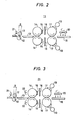
- FIG. 2 there is shown therein schematic side elevational view of an image transfer device according to a preferred embodiment of the present invention.
- an image sheet on which an image is formed and an image-receiving sheet are superposed and inserted between and past a pair of insertion rollers 12.
- a support plate for reinforcing and guiding the image sheet and the image-receiving sheet and a cover sheet for protecting the sheets may be superposed upon the sheets.
- the reinforcing and guiding support plate should preferably be made of a material having good thermal conductivity, such as aluminum.
- a transfer device 11 has either a non-contact or contact-type sensor 21 for detecting the insertion of the superposed sheets to operate the transfer device 11, the pair of insertion rollers 12, a plate heater 13 for preheating the superposed sheets as fed from the insertion rollers 12, and a pair of heated rollers 14 for sandwiching and feeding the superposed sheets as heated by the plate heater 13 and heating the superposed sheets up to about 150°C under pressure.
- the transfer device 11 also includes a pair of rollers 17 for -sandwiching and feeding the superposed sheets between which the image has been transferred by the heated rollers 14; the rollers 17 may be rollers for cooling the superposed sheets to a predetermined temperature.
- the image transfer device may further be provided with a cooling section composed of a cooling plate 18 and a cooling fan 20 for additionally cooling the superposed sheets, temperature sensors 15 for controlling the temperature of the heated rollers 14, slitted pipes 19 for blowing cool air against the cooling rollers 17, and thermally insulating members 16 for preventing the heat of the heated rollers 14 from being transferred to the rollers 17.
- a cooling section composed of a cooling plate 18 and a cooling fan 20 for additionally cooling the superposed sheets
- temperature sensors 15 for controlling the temperature of the heated rollers 14
- slitted pipes 19 for blowing cool air against the cooling rollers 17
- thermally insulating members 16 for preventing the heat of the heated rollers 14 from being transferred to the rollers 17.
- the upper insertion roller 12 is angularly displaced from the lower insertion roller 12 toward the plate heater 13 by an angle of for feeding the superimposed sheets while contacting the plate heater 13 so that the superimposed sheets can be well heated.
- the plate heater 3 serves to minimize any temperature reduction of the heated rollers 14 as they process the superimposed sheets, and also to preheat the sheets to thereby avoid abrupt heating thereof.
- the plate heater 13 ⁇ is heated to a temperature controlled by the temperature sensors 15.
- the heated rollers 14 each, accommodate a Nichrome wire and a heat-radiating lamp such as a halogen lamp, and are rotatable for- heating and pressing the superimposed sheets to effect reliable transfer of the image between the sheets.
- the heated rollers 14 have surface layers which should preferably be formed of heat-resistant rubber or metal.
- the temperature of the heated rollers 14 is controlled by the temperature sensors 15 to a level suitable for image transfer operations, the heated rollers 14 may additionally be heated on their surfaces with heat radiated by an auxiliary heating device such as a heat-radiating lamp to prevent a temperature reduction on the roller surfaces which would otherwise occur each time a superimposed sheet passed the heat rollers 14.
- the feeding rollers 17 which feed the superposed sheets may be effective to make the superposed sheets easier to handle by cooling the sheets. More specifically, in the ordinary process of preparing a color proof, images of four colors are transferred, and hence four transfer cycles have to be repeated. The feeding rollers 17 are employed to increase the efficiency of such repeated image transfer operations.
- Each of the feeding rollers 17 is constructed of heat-resistant rubber or metal, and may have its outer surface cooled by cool air blown from one of the slitted pipes 19.
- the feeding rollers 17 may be cooled by a cooling medium or cool air passed therethrough.
- the cooling plate 18 is made of a metal with good thermal conductivity, such as aluminum, and may be cooled by a cooling medium passing therethrough.
- the cooling fan 20 cools the superimposed sheets from above and also cools the cooling plate 18.
- a contact-type sensor such as a photoelectric sensor for detecting when the superposed sheets are discharged onto the cooling plate 18.
- the heated rollers 14 and the feeding rollers 17 are provided in single pairs, they may be provided in plural pairs.
- the transfer device 11 has been described as being started by the sensor 21, the device may be started by a manual switch.
- the thermally insulating members 16 which prevent thermal transfer between the plate heater 13 or the heated rollers 14 and the feeding rollers 17 or the cooling plate 18 may be in the form of plates constructed of stainless steel, plastics, foamed plastic, glass wool, or a composite material of these.
- Fig. 3 shows another embodiment in which auxiliary heating units 22 are added to the arrangement of Fig. 2 for preventing the surface temperature of the heated rollers 14 from being locally lowered due to insertion of the sheets. Operation of the auxiliary heating units 22 is started by the temperature sensors 15 upon detection of a certain temperature of the heated rollers 14. Alternatively, the auxiliary heating units 22 may be started, after a predetermined time established by a timer TM 2 (see Fig. 6) following the detection of the sheets by the sensor 21.
- a timer TM 2 see Fig. 6
- Each of the auxiliary heating devices 22 may include a reflecting plate for effectively reflecting the radiated heat.
- the heater may be constructed with a Nichrome wire or a heat-radiating lamp such as a halogen lamp. Since the auxiliary heating units 22 prevent the surface temperature of the heated rollers 14 from being locally lowered due to insertion of the sheets, they should preferably start operation when portions of the heated rollers 14 where the surface temperature has been lowered due to insertion of the sheets reach a position near the auxiliary heating units 22 (when the heated rollers 14 have made about 3/4 revolution after the leading ends of the sheets reached the heated rollers 14 in the embodiment of Fig. 3).
- the auxiliary heating units 22 also should preferably stop operating when the trailing ends of the sheets have left the heated rollers 14 and portions of the heated rollers 14 which contact the trailing ends of the sheets have reached the auxiliary heating units 22 (when the heated rollers 14 have made about 3/4 revolution after the trailing ends of the sheets have left the heated rollers 14 in Fig. 3).
- Such operation may be effected by a combination of the sensor 21 which detects the sheets and a timer, or by a separate sensor. For example, when the trailing ends of the sheets leave the sensor 21, a timer TM 3 (Fig. 6) starts and the auxiliary heating units 22 stop after a predetermined time so that the surface temperature of the heated rollers 14 is kept at a constant temperature.
- the temperature sensors 15 should preferably be disposed in positions out of contact with the sheets (at axial ends of the heated rollers 14) since if the temperature sensors were disposed centrally, widthwise of the heated rollers 14, they would be affected by variations in -temperature due to insertion of the sheets, resulting in difficulty in controlling the temperature.
- auxiliary heating units 22 in the embodiment of Fig. 3 are the same as those shown in Fig. 2.
- the image transfer device 11 of the invention can automatically perform a succession of image transfer steps from the insertion of superimposed sheets to the cooling thereof for thereby increasing the rate and efficiency of image transfer operations.
- the image transfer device 11 is arranged such that the superposed sheets are fed to the heated rollers 14 after the sheets have been preheated by the plate heater 13, or the plate heater 13 and the auxiliary heating units 22. With this arrangement, any local temperature reduction of the heated rollers 14 as the sheets are inserted therebetween is suppressed, the temperature thereof stabilized, and the sheets thus prevented from being abruptly heated to guard against transfer irregularities.
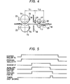
- Fig. 4 is a schematic view showing another embodiment of the present invention. According to this embodiment, no preliminary heating unit is provided in the apparatus. When a guide plate is inserted in the apparatus, heating and transferring are carried out by heated rollers 14, and thereafter, the auxiliary heating unit 22 and cooling fan 20 are operated simultaneously upon detection of the guide plate by the sensor 21.
- the sensor 21 is provided at a distance L l from the nip between the heated rollers 14 equal to three-quarters of the circumference of one of the heated rollers 14.
- the auxiliary heating unit 22 may be controlled by the output of the sensor 21, in which case it is unnecessary to provide a timer. As a result, a simple and economical structure is provided, and no mechanical modification is required, even if the travelling velocity is changed.
- the length L l is equal to three-quarters of the circumference of one of the heated rollers 14.
- the length L l may be set to correspond to the distance between the auxiliary heating units 22 and confronting portion of the respective heated rollers 14.
- the operation of the cooling fan 20 is terminated after a predetermined time, established by a timer (not shown), corresponding to movement of a guide plate through a distance L 2 after the sensor 21 has detected the guide plate.
- the fan 20 can be continuously operated.
- Fig. 5 is a timing diagram indicating a typical sequence of operations of the heated rollers 14, feeding rollers 17, sensor 21, auxiliary heating unit 22, cooling- fan 20, and timer.
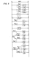
- Fig. 6 is an electrical circuit diagram of a control circuit used to control the operations of these units. In Fig.
- Hl indicates the heating element of the upper heated roller; H2, the heating element of the lower heated roller; H3, the heating element of the upper auxiliary heater; H4, the heating element of the lower auxiliary heater; TH 1 and TH 2 , temperature control units for the upper and lower heated rollers, respectively; TH l -l and TH 2 -1, contacts of the temperature control units TH 1 and TH 2 , respectively; K 1 , K 2 , K 5 , K 6 , K 7 and Kg, relays; K 1 -1, K 2 -1, K 5 -1, K 6 -1, K7 -1 and K 9 -1, contacts of the relays K 1 , K 2 , K 5 , K 6 , K 7 and Kg, respectively; K 8 , another relay; K 8 -1 to K 8 -3, contacts of the relay K 8 ; CP 1 , the sensor 21; CP 1 -1, a switch operated by the output of the sensor CP 1 ; TM 2 , the timer for determining the ON time
- Fig. 1A is a plan view of a positioning plate employed in a method of the present invention
- Fig. 1B is a side elevational view showing an intermediate step of the method of the present invention
- Fig. 1C is a side elevational view illustrative of a condition after the method of the invention has been completed.
- image sheets on which images are formed after color separation and an image-receiving- sheet are first perforated with positioning holes. Then, the image sheets are exposed and developed.
- the positioning holes are formed in complementary relation to the shapes, for example, circular and oval, of two pins 2 and 3 on a positioning plate 1 shown in Fig. lA.
- the differently shaped pins 2 and 3 and the complementarily shaped holes are interfitted to register the images.
- the image-receiving sheet denoted at 5 in Fig. lC
- a support plate 4 see Fig. 1B
- the image sheet denoted at 6 in Fig. lC, carrying a first color image to be transferred first, is then placed on the image-receiving sheet 5 and positioned by the pins 2 and 3.
- a cover sheet 7 is put over the image sheet 6 and mounted in wrapping relation on a front lower surface of the support plate 4, followed by removal of the positioning plate 1.
- the color sheet may be superposed on the support plate 4 at the front edge thereof.
- the support plate 4 is in the form of a thin plate with good thermal conductivity, made, for instance, of aluminum.
- the support plate 4 has a thickness of about 0.5 mm, taking into account the desired thermal conductivity and rigidness.
- the support plate 4 has holes through which the pins 2 and 3 can be inserted.
- the surface of the support plate 4 on which the image-receiving sheet 5 is to be placed is provided with a white layer of anodized aluminum for allowing visible fine positional adjustment.
- the assembly of the support plate 4, the image-receiving sheet 5, the image sheet 6, and the cover sheet 7 is sandwiched between a pair of upper and lower heated rollers and fed in the direction of the arrow (Fig. 1C) while being pressed and heated. During such a process, or in any other handling process, the support plate 4 serves to make the assembly rigid.
- the cover sheet 7 has a thickness of about 100 microns, determined taking into account the desired thermal conductivity and ease of manipulation, and is made of plastics such as polyethyleneterephthalate (PET).
- PET polyethyleneterephthalate
- the surface of the cover sheet 7 may be coated with silicone or a fluorine-contained resin to prevent the adhesion of the cover sheet 7 to the image sheet 6.
- the cover sheet 7 is effective in pressing the image sheet 6 and the image-receiving sheet 5 down against the support plate 4 to guard against positional displacement of-the sheets 5 and 6.
- the cover sheet 7 also serves to prevent dust and dirt on the pressing and heating members or heated rollers from being deposited on the assembly and also to prevent the adhesive of an adhesive layer on the image-receiving sheet 5 from being deposited on the pressing and heating members. Since the support plate 4 is rigid, the assembly can be carried around easily, and the sheets can be protected against positional displacement during movement.
- the image-receiving sheet 5 with a previous image transferred thereon and a next image sheet 6 are positioned relatively to each other in the manner described above, and adjusted slightly for image registration under visual supervision. Thereafter, the above image transfer cycle is repeated.
- the fine adjustment under visual supervision may be assisted by light illumination from a higher light source.
- the support plate 4 and the cover sheet 7 have been described as being formed of aluminum and polyethyleneterephthalate, respectively, the present invention is not limited to such specific examples.
- the support plate 4 may be formed of any practical material, provided it has good thermal conductivity and rigidity.
- the cover sheet 7 is not restricted to plastics, but may be in the form of a thin metal sheet, provided it is a good thermal conductor and can be handled with ease.
- the surface of the support plate 4 has been described as being formed of anodized aluminum, the present invention is not limited to such specific example.
- the surface of the support plate 4 may be coated with white paint so as to enable fine positional adjustment for image registration.
- the support plate 4 is placed beneath the image-receiving sheet 5 and the image sheet 6 is covered with the cover sheet 7.
- the overall assembly is therefore rendered rigid and protected from dust deposits. The assembly can easily be handled so that the transfer process can be effected efficiently.
- the assembly With the assembly being of an increased degree of rigidity, the assembly is prevented from deformation such as warpage when pressed by the heated rollers. Accordingly, the image sheet 6 and the image-receiving sheet 5 are prevented from being positionally displaced and the sharpness of the image is increased.
- the surface of the support plate 4 has a white anodized layerof aluminum, fine positional adjustment for image registration can easily be effected under visual supervision.
- the rigidity of the support plate 4 permits the assembly to be carried around easily and is effective in the prevention of positional displacement of the sheets.
- the method of the invention is applicable to the re-transfer of a proof from the image-receiving sheet 5 to a print sheet and the matting of a test print on a print sheet.
Landscapes
- Physics & Mathematics (AREA)
- General Physics & Mathematics (AREA)
- Thermal Transfer Or Thermal Recording In General (AREA)
Applications Claiming Priority (4)
| Application Number | Priority Date | Filing Date | Title |
|---|---|---|---|
| JP59112020A JPS60255497A (ja) | 1984-05-31 | 1984-05-31 | 画像転写方法 |
| JP112020/84 | 1984-05-31 | ||
| JP11202184A JPS60255498A (ja) | 1984-05-31 | 1984-05-31 | 画像転写装置 |
| JP112021/84 | 1984-05-31 |
Publications (3)
| Publication Number | Publication Date |
|---|---|
| EP0163300A2 true EP0163300A2 (de) | 1985-12-04 |
| EP0163300A3 EP0163300A3 (en) | 1987-08-26 |
| EP0163300B1 EP0163300B1 (de) | 1992-08-19 |
Family
ID=26451281
Family Applications (1)
| Application Number | Title | Priority Date | Filing Date |
|---|---|---|---|
| EP85106618A Expired EP0163300B1 (de) | 1984-05-31 | 1985-05-29 | Verfahren und Vorrichtung zur Bildübertragung |
Country Status (4)
| Country | Link |
|---|---|
| US (1) | US4659927A (de) |
| EP (1) | EP0163300B1 (de) |
| CA (1) | CA1247932A (de) |
| DE (1) | DE3586510T2 (de) |
Cited By (6)
| Publication number | Priority date | Publication date | Assignee | Title |
|---|---|---|---|---|
| EP0227041A3 (en) * | 1985-12-20 | 1988-10-19 | Fuji Photo Film Co., Ltd. | Image recording apparatus |
| EP0474815A4 (en) * | 1990-03-12 | 1993-03-17 | Western Litho Plate & Supply Co. | Apparatus for making color proof laminations |
| EP0640473A1 (de) * | 1993-08-23 | 1995-03-01 | E.I. Du Pont De Nemours And Company | Farbprüffolienherstellungsvorrichtung mit Temperaturkontrolle |
| EP0816073A1 (de) * | 1996-07-05 | 1998-01-07 | Fuji Photo Film Co., Ltd. | Wärmeübertragungsvorrichtung für Bogenzusammenstellung |
| EP0789277A3 (de) * | 1996-02-08 | 1998-01-21 | EASTMAN KODAK COMPANY (a New Jersey corporation) | Verfahren zur Herstellung eines Druckvorbereitungs-Farbprüferbildes und intermediären Empfangselements und Trägerplatte dafür |
| EP0859281A1 (de) * | 1997-02-14 | 1998-08-19 | Eastman Kodak Company | Trägerplatte-Element zur Verwendung in einem Druckvorbereitungs-Farbprüferbild |
Families Citing this family (20)
| Publication number | Priority date | Publication date | Assignee | Title |
|---|---|---|---|---|
| US4799085A (en) * | 1986-04-03 | 1989-01-17 | Fuji Photo Film Co., Ltd. | Image recording apparatus and method |
| US4783683A (en) * | 1986-04-03 | 1988-11-08 | Fuji Photo Film Co., Ltd. | Image recording apparatus |
| US4737822A (en) * | 1986-04-22 | 1988-04-12 | Fuji Photo Film Co., Ltd. | Image recording apparatus and method |
| FR2602719A1 (fr) * | 1986-07-28 | 1988-02-19 | Ecamo Sa | Dispositif microondes destine a la fusion de poudre thermogravure pour impression en relief |
| US4962314A (en) * | 1988-07-26 | 1990-10-09 | Fuji Photo Film Co., Ltd. | Image transfer apparatus |
| US4992833A (en) * | 1989-08-10 | 1991-02-12 | Eastman Kodak Company | Fixing method and apparatus having a transfer-fixing chilling drum |
| US5168286A (en) * | 1989-08-18 | 1992-12-01 | Mita Industrial Co., Ltd. | Electrophotographic image forming apparatus and a thermal printer for such apparatus for adding supplemental data |
| JP2795962B2 (ja) * | 1990-04-19 | 1998-09-10 | 富士写真フイルム株式会社 | 画像転写装置および画像転写方法 |
| US5236542A (en) * | 1990-11-15 | 1993-08-17 | E. I. Du Pont De Nemours And Company | Off-press laminating apparatus |
| US5075722A (en) * | 1990-11-15 | 1991-12-24 | E. I. Du Pont De Nemours And Company | Off-press laminating method |
| JP3073071B2 (ja) | 1990-11-15 | 2000-08-07 | イー・アイ・デュポン・ドウ・ヌムール・アンド・カンパニー | オフプレス積層装置および方法 |
| US5563234A (en) * | 1993-08-23 | 1996-10-08 | E. I. Du Pont De Nemours And Company | Carrier plate for a lamination process |
| US5641374A (en) * | 1995-03-16 | 1997-06-24 | Minnesota Mining And Manufacturing Company | Apparatus and method for preventing defects during the lamination of materials |
| KR200173488Y1 (ko) * | 1999-09-04 | 2000-03-15 | 주식회사지엠피 | 라미네이터용 히팅로울러의 세라믹히타 |
| US6252653B1 (en) | 1999-10-12 | 2001-06-26 | Burgess Industries Inc. | Rotary thermal desensitizer of developer for photosensitive copy sheet material |
| EP1116600A3 (de) * | 2000-01-11 | 2002-03-06 | Hewlett-Packard Company, A Delaware Corporation | Vorrichtung und Verfahren zum Binden von Blättern |
| US6702915B2 (en) * | 2001-10-26 | 2004-03-09 | Eastman Kodak Company | Lamination envelope |
| US9676179B2 (en) * | 2005-04-20 | 2017-06-13 | Zih Corp. | Apparatus for reducing flash for thermal transfer printers |
| MX2007013199A (es) * | 2005-04-20 | 2008-11-04 | Zih Corp | Procedimiento y sistema para transferencia de imagen de dos lados de un solo paso. |
| WO2010080940A2 (en) * | 2009-01-10 | 2010-07-15 | Zih Corp. | Apparatus for reducing flash for thermal transfer printers |
Family Cites Families (13)
| Publication number | Priority date | Publication date | Assignee | Title |
|---|---|---|---|---|
| US3129328A (en) * | 1960-05-04 | 1964-04-14 | Minnesota Mining & Mfg | Thermographic copy machine comprising means to tension the sheet composite in the irradiation zone |
| NL275378A (de) * | 1961-03-06 | |||
| US3214583A (en) * | 1962-01-22 | 1965-10-26 | Minnesota Mining & Mfg | Adapter |
| DE1171269B (de) * | 1962-09-25 | 1964-05-27 | Zindler Lumoprint Kg | Verfahren zum Herstellen eines UEbertragungs-bildes und Vorrichtung zur Durchfuehrung dieses Verfahrens |
| DE1522921B2 (de) * | 1966-06-29 | 1975-10-02 | Gerhard 1000 Berlin Ritzerfeld | Thermokopiergerät |
| DE1671534A1 (de) * | 1967-03-29 | 1972-02-03 | Ostwald Heinz G | Verfahren zum Waermekopieren und Heissversiegeln |
| US3813516A (en) * | 1969-12-29 | 1974-05-28 | Ibm | Apparatus for temperature control for a heated rotating cylinder |
| BE789229A (fr) * | 1971-12-13 | 1973-01-15 | Ritzerfeld Gerhard | Procede et dispositif d'etablissement thermographique de formesa image inversee |
| DE2606707A1 (de) * | 1976-02-17 | 1977-08-18 | Gerhard Ritzerfeld | Thermokopiergeraet |
| US4071735A (en) * | 1976-11-01 | 1978-01-31 | Xerox Corporation | Externally heated low-power roll fuser |
| DE3170134D1 (en) * | 1980-09-02 | 1985-05-30 | Fuji Photo Film Co Ltd | Method for immunochemical measurement |
| US4506442A (en) * | 1982-09-29 | 1985-03-26 | Lenkeit Industries, Inc. | Method and apparatus for stacking a plurality of laminate layers to form a composite board |
| US4512650A (en) * | 1983-11-04 | 1985-04-23 | Eastman Kodak Company | Fuser apparatus having a uniform heat distribution |
-
1985
- 1985-05-29 DE DE8585106618T patent/DE3586510T2/de not_active Expired - Lifetime
- 1985-05-29 EP EP85106618A patent/EP0163300B1/de not_active Expired
- 1985-05-31 CA CA000482916A patent/CA1247932A/en not_active Expired
- 1985-05-31 US US06/739,596 patent/US4659927A/en not_active Expired - Lifetime
Cited By (9)
| Publication number | Priority date | Publication date | Assignee | Title |
|---|---|---|---|---|
| EP0227041A3 (en) * | 1985-12-20 | 1988-10-19 | Fuji Photo Film Co., Ltd. | Image recording apparatus |
| EP0474815A4 (en) * | 1990-03-12 | 1993-03-17 | Western Litho Plate & Supply Co. | Apparatus for making color proof laminations |
| EP0640473A1 (de) * | 1993-08-23 | 1995-03-01 | E.I. Du Pont De Nemours And Company | Farbprüffolienherstellungsvorrichtung mit Temperaturkontrolle |
| US5476568A (en) * | 1993-08-23 | 1995-12-19 | E. I. Du Pont De Nemours And Company | Pre-proof temperature controlling assembly |
| US5487801A (en) * | 1993-08-23 | 1996-01-30 | E. I. Du Pont De Nemours And Company | Pre-proof temperature controlling assembly |
| EP0789277A3 (de) * | 1996-02-08 | 1998-01-21 | EASTMAN KODAK COMPANY (a New Jersey corporation) | Verfahren zur Herstellung eines Druckvorbereitungs-Farbprüferbildes und intermediären Empfangselements und Trägerplatte dafür |
| EP0816073A1 (de) * | 1996-07-05 | 1998-01-07 | Fuji Photo Film Co., Ltd. | Wärmeübertragungsvorrichtung für Bogenzusammenstellung |
| US5895156A (en) * | 1996-07-05 | 1999-04-20 | Fuji Photo Film Co., Ltd. | Heat transfer device for sheet assembly |
| EP0859281A1 (de) * | 1997-02-14 | 1998-08-19 | Eastman Kodak Company | Trägerplatte-Element zur Verwendung in einem Druckvorbereitungs-Farbprüferbild |
Also Published As
| Publication number | Publication date |
|---|---|
| EP0163300A3 (en) | 1987-08-26 |
| CA1247932A (en) | 1989-01-03 |
| US4659927A (en) | 1987-04-21 |
| DE3586510T2 (de) | 1993-01-28 |
| EP0163300B1 (de) | 1992-08-19 |
| DE3586510D1 (de) | 1992-09-24 |
Similar Documents
| Publication | Publication Date | Title |
|---|---|---|
| US4659927A (en) | Image transfer apparatus and method | |
| US5055884A (en) | Electrostatographic equipment with multiplex fuser | |
| US5053828A (en) | Electrostatographic equipment having a multiple function fusing and image transfer roller | |
| JPH04225375A (ja) | 電気的記録のプリンタ用のイメージ転写方法 | |
| EP0607649B1 (de) | Bildübertragungsgerät | |
| US6144395A (en) | Printer with preheating of sheet | |
| JP4254184B2 (ja) | 光沢処理装置および画像形成装置 | |
| JPH0318705B2 (de) | ||
| JPH0560106B2 (de) | ||
| JPH09171311A (ja) | 画像形成装置 | |
| JPH0679186B2 (ja) | 定着装置 | |
| JPH09190112A (ja) | 定着装置及び画像形成装置 | |
| US5730833A (en) | Image transfer apparatus | |
| JPH04345187A (ja) | 定着装置 | |
| JPH1016187A (ja) | シート体加熱転写装置 | |
| US12124202B2 (en) | Image forming apparatus | |
| JP2836308B2 (ja) | トレー付き画像転写装置 | |
| JP2970279B2 (ja) | トレイ付き画像転写装置 | |
| JPH0232374A (ja) | 画像形成装置 | |
| JPS63177183A (ja) | 転写装置 | |
| JPH04223465A (ja) | 画像転写方法 | |
| JPS59186852U (ja) | カラ−複写装置 | |
| JP2000122307A (ja) | 画像転写装置 | |
| JPH0772694A (ja) | カラー電子写真記録装置 | |
| JPH01129276A (ja) | 画像形成装置 |
Legal Events
| Date | Code | Title | Description |
|---|---|---|---|
| PUAI | Public reference made under article 153(3) epc to a published international application that has entered the european phase |
Free format text: ORIGINAL CODE: 0009012 |
|
| AK | Designated contracting states |
Designated state(s): DE FR GB |
|
| PUAL | Search report despatched |
Free format text: ORIGINAL CODE: 0009013 |
|
| AK | Designated contracting states |
Kind code of ref document: A3 Designated state(s): DE FR GB |
|
| 17P | Request for examination filed |
Effective date: 19880217 |
|
| 17Q | First examination report despatched |
Effective date: 19900615 |
|
| GRAA | (expected) grant |
Free format text: ORIGINAL CODE: 0009210 |
|
| AK | Designated contracting states |
Kind code of ref document: B1 Designated state(s): DE FR GB |
|
| REF | Corresponds to: |
Ref document number: 3586510 Country of ref document: DE Date of ref document: 19920924 |
|
| ET | Fr: translation filed | ||
| PLBE | No opposition filed within time limit |
Free format text: ORIGINAL CODE: 0009261 |
|
| STAA | Information on the status of an ep patent application or granted ep patent |
Free format text: STATUS: NO OPPOSITION FILED WITHIN TIME LIMIT |
|
| 26N | No opposition filed | ||
| REG | Reference to a national code |
Ref country code: GB Ref legal event code: IF02 |
|
| PGFP | Annual fee paid to national office [announced via postgrant information from national office to epo] |
Ref country code: FR Payment date: 20040510 Year of fee payment: 20 |
|
| PGFP | Annual fee paid to national office [announced via postgrant information from national office to epo] |
Ref country code: GB Payment date: 20040526 Year of fee payment: 20 |
|
| PGFP | Annual fee paid to national office [announced via postgrant information from national office to epo] |
Ref country code: DE Payment date: 20040610 Year of fee payment: 20 |
|
| PG25 | Lapsed in a contracting state [announced via postgrant information from national office to epo] |
Ref country code: GB Free format text: LAPSE BECAUSE OF EXPIRATION OF PROTECTION Effective date: 20050528 |
|
| REG | Reference to a national code |
Ref country code: GB Ref legal event code: PE20 |
|
| REG | Reference to a national code |
Ref country code: GB Ref legal event code: 732E |