EP0163595A2 - Dispositif de contrôle pour couper des bandes - Google Patents
Dispositif de contrôle pour couper des bandes Download PDFInfo
- Publication number
- EP0163595A2 EP0163595A2 EP85730064A EP85730064A EP0163595A2 EP 0163595 A2 EP0163595 A2 EP 0163595A2 EP 85730064 A EP85730064 A EP 85730064A EP 85730064 A EP85730064 A EP 85730064A EP 0163595 A2 EP0163595 A2 EP 0163595A2
- Authority
- EP
- European Patent Office
- Prior art keywords
- sheet
- shear
- length
- rotary cutter
- output
- Prior art date
- Legal status (The legal status is an assumption and is not a legal conclusion. Google has not performed a legal analysis and makes no representation as to the accuracy of the status listed.)
- Granted
Links
- 238000005520 cutting process Methods 0.000 title claims abstract description 25
- 230000002093 peripheral effect Effects 0.000 claims description 2
- 238000004519 manufacturing process Methods 0.000 description 3
- 238000010586 diagram Methods 0.000 description 2
- 230000003292 diminished effect Effects 0.000 description 1
- 230000000694 effects Effects 0.000 description 1
- 238000000034 method Methods 0.000 description 1
Images


Classifications
-
- B—PERFORMING OPERATIONS; TRANSPORTING
- B23—MACHINE TOOLS; METAL-WORKING NOT OTHERWISE PROVIDED FOR
- B23D—PLANING; SLOTTING; SHEARING; BROACHING; SAWING; FILING; SCRAPING; LIKE OPERATIONS FOR WORKING METAL BY REMOVING MATERIAL, NOT OTHERWISE PROVIDED FOR
- B23D36/00—Control arrangements specially adapted for machines for shearing or similar cutting, or for sawing, stock which the latter is travelling otherwise than in the direction of the cut
- B23D36/0091—Control arrangements specially adapted for machines for shearing or similar cutting, or for sawing, stock which the latter is travelling otherwise than in the direction of the cut for machines with more than one cutting, shearing, or sawing devices
-
- Y—GENERAL TAGGING OF NEW TECHNOLOGICAL DEVELOPMENTS; GENERAL TAGGING OF CROSS-SECTIONAL TECHNOLOGIES SPANNING OVER SEVERAL SECTIONS OF THE IPC; TECHNICAL SUBJECTS COVERED BY FORMER USPC CROSS-REFERENCE ART COLLECTIONS [XRACs] AND DIGESTS
- Y10—TECHNICAL SUBJECTS COVERED BY FORMER USPC
- Y10T—TECHNICAL SUBJECTS COVERED BY FORMER US CLASSIFICATION
- Y10T83/00—Cutting
- Y10T83/141—With means to monitor and control operation [e.g., self-regulating means]
- Y10T83/148—Including means to correct the sensed operation
-
- Y—GENERAL TAGGING OF NEW TECHNOLOGICAL DEVELOPMENTS; GENERAL TAGGING OF CROSS-SECTIONAL TECHNOLOGIES SPANNING OVER SEVERAL SECTIONS OF THE IPC; TECHNICAL SUBJECTS COVERED BY FORMER USPC CROSS-REFERENCE ART COLLECTIONS [XRACs] AND DIGESTS
- Y10—TECHNICAL SUBJECTS COVERED BY FORMER USPC
- Y10T—TECHNICAL SUBJECTS COVERED BY FORMER US CLASSIFICATION
- Y10T83/00—Cutting
- Y10T83/465—Cutting motion of tool has component in direction of moving work
- Y10T83/4653—With means to initiate intermittent tool action
- Y10T83/4656—Tool moved in response to work-sensing means
- Y10T83/4659—With means to vary "length" of product
- Y10T83/4662—To vary an end-product "length" [e.g., "crop cut"]
-
- Y—GENERAL TAGGING OF NEW TECHNOLOGICAL DEVELOPMENTS; GENERAL TAGGING OF CROSS-SECTIONAL TECHNOLOGIES SPANNING OVER SEVERAL SECTIONS OF THE IPC; TECHNICAL SUBJECTS COVERED BY FORMER USPC CROSS-REFERENCE ART COLLECTIONS [XRACs] AND DIGESTS
- Y10—TECHNICAL SUBJECTS COVERED BY FORMER USPC
- Y10T—TECHNICAL SUBJECTS COVERED BY FORMER US CLASSIFICATION
- Y10T83/00—Cutting
- Y10T83/465—Cutting motion of tool has component in direction of moving work
- Y10T83/4705—Plural separately mounted flying cutters
-
- Y—GENERAL TAGGING OF NEW TECHNOLOGICAL DEVELOPMENTS; GENERAL TAGGING OF CROSS-SECTIONAL TECHNOLOGIES SPANNING OVER SEVERAL SECTIONS OF THE IPC; TECHNICAL SUBJECTS COVERED BY FORMER USPC CROSS-REFERENCE ART COLLECTIONS [XRACs] AND DIGESTS
- Y10—TECHNICAL SUBJECTS COVERED BY FORMER USPC
- Y10T—TECHNICAL SUBJECTS COVERED BY FORMER US CLASSIFICATION
- Y10T83/00—Cutting
- Y10T83/525—Operation controlled by detector means responsive to work
- Y10T83/527—With means to control work-responsive signal system
- Y10T83/53—To change length of product
-
- Y—GENERAL TAGGING OF NEW TECHNOLOGICAL DEVELOPMENTS; GENERAL TAGGING OF CROSS-SECTIONAL TECHNOLOGIES SPANNING OVER SEVERAL SECTIONS OF THE IPC; TECHNICAL SUBJECTS COVERED BY FORMER USPC CROSS-REFERENCE ART COLLECTIONS [XRACs] AND DIGESTS
- Y10—TECHNICAL SUBJECTS COVERED BY FORMER USPC
- Y10T—TECHNICAL SUBJECTS COVERED BY FORMER US CLASSIFICATION
- Y10T83/00—Cutting
- Y10T83/525—Operation controlled by detector means responsive to work
- Y10T83/531—With plural work-sensing means
-
- Y—GENERAL TAGGING OF NEW TECHNOLOGICAL DEVELOPMENTS; GENERAL TAGGING OF CROSS-SECTIONAL TECHNOLOGIES SPANNING OVER SEVERAL SECTIONS OF THE IPC; TECHNICAL SUBJECTS COVERED BY FORMER USPC CROSS-REFERENCE ART COLLECTIONS [XRACs] AND DIGESTS
- Y10—TECHNICAL SUBJECTS COVERED BY FORMER USPC
- Y10T—TECHNICAL SUBJECTS COVERED BY FORMER US CLASSIFICATION
- Y10T83/00—Cutting
- Y10T83/525—Operation controlled by detector means responsive to work
- Y10T83/54—Actuation of tool controlled by work-driven means to measure work length
-
- Y—GENERAL TAGGING OF NEW TECHNOLOGICAL DEVELOPMENTS; GENERAL TAGGING OF CROSS-SECTIONAL TECHNOLOGIES SPANNING OVER SEVERAL SECTIONS OF THE IPC; TECHNICAL SUBJECTS COVERED BY FORMER USPC CROSS-REFERENCE ART COLLECTIONS [XRACs] AND DIGESTS
- Y10—TECHNICAL SUBJECTS COVERED BY FORMER USPC
- Y10T—TECHNICAL SUBJECTS COVERED BY FORMER US CLASSIFICATION
- Y10T83/00—Cutting
- Y10T83/525—Operation controlled by detector means responsive to work
- Y10T83/541—Actuation of tool controlled in response to work-sensing means
Definitions
- the present invention relates to a controller for cutting sheet material so that inferior or incomplete sheet material is eliminated, and which is applicable to a rotary shear control unit for use in a machine for manufacturing corrugated cardboard.
- FIGS. 1 and 2 there is shown a prior art shear a for removing inferior sheet material, and a slitter unit b and a rotary cutter c are disposed subsequently to the shear. As shown in FIG. 2, such a shear is used to separate or remove an inferior portion d of the sheet material or change an order of units of the next stage.
- the present invention has been proposed to remove the prior art drawbacks and is to provide a controller for cutting sheet material in which a useless short piece of sheet produced at the starting of a shear in the prior art is not produced.
- the controller for cutting sheet material comprises means for detecting cutting conditions of a rotary cutter, means for calculating a length of sheet passing until the sheet is first cut after a shear is started, and means for controlling a 0start timing of the shear so that a sheet trailing edge concides with a sheet cut portion cut by the rotary cutter.
- the start timing is controlled on the basis of a time f(v) required until the velocity of the shear reaches a given sheet velocity v, a distance D between the shear and the rotary cutter, a length L of sheet to be cut, and the number n of sheet to be cut, as follows:
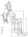
- numeral 1 denotes sheet material which is sequentially fed and cut in a proper length
- numeral 2 a rotary cutter and 3 a shear
- Numeral 4 denotes a pulse generator for detecting an amount of movement of the sheet material land which is mounted in a measuring roller pressed on a surface of the sheet material 1 with a proper pressure so that pulses proportional to the amount of movement of the sheet material are produced.
- Numeral 5 denotes a voltage generator for detecting a velocity of movement of the sheet material 1 and which is mounted in a measuring roller similar to that of the pulse generator 4 so that a voltage proportional to the velocity of movement of the sheet material is produced.
- Numeral 6 denotes a sensor such as a proximity switch for detecting the completion of cutting the sheet material by the rotary cutter 2.
- Numeral 7 denotes a switch for presetting a length of sheet to be cut by the rotary cutter, numeral 8 a switch for presetting a length of sheet between the shear and the rotary cutter, and numeral 9 an operational switch for starting the shear.
- Numeral 10 denotes a reverse rotation decision circuit for generating a normal rotation pulse and a reverse rotation pulse in accordance with an input signal of the pulse generator 4.
- Numeral 11 denotes a counter or an up-and-down counter having a preset input terminal 25, a normal rotation pulse input terminal 26 and a reverse rotation pulse input terminal 27.
- Numeral 12 denotes an arithmetic operation unit for calculating a length of sheet passing until the sheet is first cut after the shear is started and which calculating the length on the basis of the movement velocity of the sheet supplied from a input terminal 28 in accordance with a predetermined functional equation and produces the result from an output terminal 29.
- Numeral 13 denotes an arithmetic operation unit for calculating a delay time of starting the shear in the form of a movement quantity of sheet required to cause a trailing edge of sheet to coincide with a cut portion of sheet by the rotary cutter, which reads in values inputted from terminals 30, 31 and 32 and supplies its calculated measured result to the counter 11.
- Numeral 14 denotes a drive circuit for the shear
- numerals 21 - 24 denote gates.
- the shear is driven by a single motor but it may be driven by a motor in a production line of the sheet material through a line shaft and a clutch.
- the voltage generator 5 produces a velocity signal of the sheet material 1 to supply it to the arithmetic operation unit 12 in which a predetermined . functional equation is given.
- the operation unit 12 performs the calculation on the basis of the inputted signal and always produces the calculated result f(v) from the terminal 29.
- FIG. 5 shows a variation in time of the sheet velocity and the cutting edge velocity of the shear when the cutting edge velocity of the shear 3 which has been first at a standstill reaches a velocity v.
- the time t required until the cutting edge velocity of the shear reaches the velocity v is given by the following equation (2): where t 0 is a signal delay time of a switch or the like, GD 2 is a flywheel effect of the shear and the motor, TM is a torque produced by the motor, TL is a load torque to the shear, and N is a rotational speed of the motor depending upon the shear velocity.
- t 0 is a signal delay time of a switch or the like
- GD 2 is a flywheel effect of the shear and the motor
- TM is a torque produced by the motor
- TL is a load torque to the shear
- N is a rotational speed of the motor depending upon the shear velocity.
- the length of sheet f(v) feeding until the sheet is cut by the shear after producing a start command for the shear is an area defined by points A, C, F and D and is expressed by the following equation (5):
- the equation (1) is obtained by substituting the equations (2) to (4) for the equation (5).
- the gates 21 to 23 are opened to supply the sheet cut length signal L from the switch 7, the sheet length signal D from the switch 8 between the shear 3 and the rotary cutter 2 and the output signal from the operation unit 12, that is, the sheet length f(v) to the operation unit 13.
- the value x thus obtained expresses the delay time in the form of the sheet length until the shear is started after the sheet material has been cut by the rotary cutter in order to cause the trailing edge of sheet to coincide with the cut portion of sheet cut by the rotary cutter.
- the sheet length data x is preset in the counter 11 and is decremented by the sheet movement pulses from the pulse generator 4.
- the counter produces an output signal.
- the output signal of the counter 11 drives the drive circuit 14 of the shear through the gate 24 to start the rotation of the shear. Consequently, the position cut by the shear coincides with the position cut by the rotary cutter.
- the controller comprising the simple logic circuit and the arithmetic operation circuit is provided in the preceding stage of the shear drive unit so that the start timing of the shear is controlled to thereby cause the trailing edge of sheet to coincide with the cut portion of sheet by the rotary cutter and therefore the making of useless short pieces of sheet material can be prevented. Further, not only the loss of sheet material but also the removal operation of useless short pieces which has been required in the sheet material production process and in the process changing operation can be diminished, and hence the productivity can be improved.
Landscapes
- Engineering & Computer Science (AREA)
- Mechanical Engineering (AREA)
- Control Of Cutting Processes (AREA)
- Machines For Manufacturing Corrugated Board In Mechanical Paper-Making Processes (AREA)
Applications Claiming Priority (2)
| Application Number | Priority Date | Filing Date | Title |
|---|---|---|---|
| JP59089024A JPS60242999A (ja) | 1984-05-02 | 1984-05-02 | 板状シ−トの不良除去切断制御装置 |
| JP89024/84 | 1984-05-02 |
Publications (3)
| Publication Number | Publication Date |
|---|---|
| EP0163595A2 true EP0163595A2 (fr) | 1985-12-04 |
| EP0163595A3 EP0163595A3 (en) | 1988-07-06 |
| EP0163595B1 EP0163595B1 (fr) | 1990-07-25 |
Family
ID=13959341
Family Applications (1)
| Application Number | Title | Priority Date | Filing Date |
|---|---|---|---|
| EP19850730064 Expired - Lifetime EP0163595B1 (fr) | 1984-05-02 | 1985-04-30 | Dispositif de contrôle pour couper des bandes |
Country Status (4)
| Country | Link |
|---|---|
| US (1) | US4594923A (fr) |
| EP (1) | EP0163595B1 (fr) |
| JP (1) | JPS60242999A (fr) |
| DE (1) | DE3578827D1 (fr) |
Cited By (1)
| Publication number | Priority date | Publication date | Assignee | Title |
|---|---|---|---|---|
| US6684749B2 (en) | 2000-05-31 | 2004-02-03 | Fosber S.P.A. | Device and method for a job change in a system for the lengthwise cutting of a weblike material |
Families Citing this family (10)
| Publication number | Priority date | Publication date | Assignee | Title |
|---|---|---|---|---|
| DE3445290A1 (de) * | 1984-12-12 | 1986-06-19 | Elastogran Maschinenbau GmbH, 2844 Lemförde | Verfahren und vorrichtung zum herstellen von hartschaumplatten, insbesondere aus polyurethan |
| US4716799A (en) * | 1986-08-12 | 1988-01-05 | Syntech International, Inc. | Ticket dispensing machine and method |
| US5172618A (en) * | 1988-05-20 | 1992-12-22 | Amada Company, Limited | Cutting machine and method for positioning end of workpiece to be cut in cutting machine |
| US4913018A (en) * | 1988-05-26 | 1990-04-03 | The Uniroyal Goodrich Tire Company | Apparatus to cut and align material in a tire building machine |
| US5777879A (en) * | 1995-09-05 | 1998-07-07 | Minnesota Mining And Manufacturing Company | Process-to-mark control system |
| US5887502A (en) * | 1995-09-26 | 1999-03-30 | Max Co., Ltd. | Rotary punching device |
| JP2999425B2 (ja) * | 1996-11-06 | 2000-01-17 | 明産株式会社 | ロータリーカッターのための接圧制御装置 |
| DE10053247A1 (de) * | 2000-10-26 | 2002-05-29 | Rexroth Indramat Gmbh | Verfahren und Vorrichtung zum Umschalten des Eingriffsabstandes eines Werkzeuges in eine vorbeilaufende Materialbahn |
| JP2005335056A (ja) * | 2004-04-26 | 2005-12-08 | K D K Kk | ラミネータの用紙切断装置 |
| ITMI20050809A1 (it) * | 2005-05-04 | 2006-11-05 | Cem Spa | Dispositivo e procedimento di taglio di moduli continui |
Family Cites Families (7)
| Publication number | Priority date | Publication date | Assignee | Title |
|---|---|---|---|---|
| US3499354A (en) * | 1968-02-29 | 1970-03-10 | Gen Electric | Temperature compensated control systems |
| US3774016A (en) * | 1971-10-04 | 1973-11-20 | Sun Chemical Corp | Control of process according to registration indicia on material being processed |
| US4020406A (en) * | 1974-06-07 | 1977-04-26 | Rengo Kabushiki Kaisha | Web cutting control system |
| US4090118A (en) * | 1976-03-25 | 1978-05-16 | Westinghouse Electric Corp. | Workpiece shear control |
| US4170155A (en) * | 1977-11-03 | 1979-10-09 | Nihon Electronic Industry Co., Ltd. | Rotary cutter for successively cutting moving material to lengths |
| US4387614A (en) * | 1981-05-20 | 1983-06-14 | Molins Machine Company | Automated web chop-out control for cut-to-mark cut-off machine |
| US4380943A (en) * | 1981-05-20 | 1983-04-26 | Molins Machine Company, Inc. | Automated cut-to-mark control for cut-off machine |
-
1984
- 1984-05-02 JP JP59089024A patent/JPS60242999A/ja active Granted
-
1985
- 1985-04-30 US US06/728,707 patent/US4594923A/en not_active Expired - Lifetime
- 1985-04-30 EP EP19850730064 patent/EP0163595B1/fr not_active Expired - Lifetime
- 1985-04-30 DE DE8585730064T patent/DE3578827D1/de not_active Expired - Lifetime
Cited By (1)
| Publication number | Priority date | Publication date | Assignee | Title |
|---|---|---|---|---|
| US6684749B2 (en) | 2000-05-31 | 2004-02-03 | Fosber S.P.A. | Device and method for a job change in a system for the lengthwise cutting of a weblike material |
Also Published As
| Publication number | Publication date |
|---|---|
| US4594923A (en) | 1986-06-17 |
| EP0163595A3 (en) | 1988-07-06 |
| JPH0366119B2 (fr) | 1991-10-16 |
| AU4188185A (en) | 1985-11-28 |
| AU584545B2 (en) | 1989-05-25 |
| JPS60242999A (ja) | 1985-12-02 |
| EP0163595B1 (fr) | 1990-07-25 |
| DE3578827D1 (de) | 1990-08-30 |
Similar Documents
| Publication | Publication Date | Title |
|---|---|---|
| EP0163595B1 (fr) | Dispositif de contrôle pour couper des bandes | |
| US3626457A (en) | Sentinel control for cutoff apparatus | |
| US4020406A (en) | Web cutting control system | |
| US4221144A (en) | Paper feed control for automatic photographic paper cutter | |
| CA1173938A (fr) | Outil de decoupage a l'emporte-piece | |
| JPH0620662B2 (ja) | ロ−タリカツタの制御方法 | |
| EP0462421B1 (fr) | Régulateur automatique du cycle opératoire d'une lame de pliage | |
| US4656857A (en) | Method for cutting uncoiled web | |
| JPS5511763A (en) | Control method and device of strip cutter | |
| CA1138962A (fr) | Appareil assurant le controle des operations de coupage en longueur et methode de fonctionnement | |
| JPH07178613A (ja) | フライングシャーの切断制御方法 | |
| JP3391051B2 (ja) | 切断機 | |
| JPH08215761A (ja) | 帯板材の曲げ加工方法及び曲げ加工装置 | |
| SU742123A1 (ru) | Способ задани скорости шлифовального круга и устройство дл его осуществлени | |
| JPH0320020Y2 (fr) | ||
| JP2969643B2 (ja) | 歯車加工装置 | |
| JP2715450B2 (ja) | カッタ・ソータシステムの切断長学習装置 | |
| JPH035334A (ja) | 硝子切断機の制御方法 | |
| SU1630890A1 (ru) | Устройство стабилизации рубки ленты шпона | |
| SU665289A1 (ru) | Система программного управлени подачей длинномерного материала | |
| SU1159799A1 (ru) | Устройство дл резки заготовок заданной длины | |
| JP2890352B2 (ja) | 自動定尺切断機のnc制御装置 | |
| JPS63163B2 (fr) | ||
| JPS63169288A (ja) | 板状シ−ト切断用の2台構成ロ−タリ−カツタの数値制御同調方法 | |
| SU980969A1 (ru) | Система управлени приводом летучих ножниц |
Legal Events
| Date | Code | Title | Description |
|---|---|---|---|
| PUAI | Public reference made under article 153(3) epc to a published international application that has entered the european phase |
Free format text: ORIGINAL CODE: 0009012 |
|
| AK | Designated contracting states |
Designated state(s): CH DE FR GB IT LI |
|
| 17P | Request for examination filed |
Effective date: 19851108 |
|
| PUAL | Search report despatched |
Free format text: ORIGINAL CODE: 0009013 |
|
| AK | Designated contracting states |
Kind code of ref document: A3 Designated state(s): CH DE FR GB IT LI |
|
| 17Q | First examination report despatched |
Effective date: 19890912 |
|
| GRAA | (expected) grant |
Free format text: ORIGINAL CODE: 0009210 |
|
| AK | Designated contracting states |
Kind code of ref document: B1 Designated state(s): CH DE FR GB IT LI |
|
| ET | Fr: translation filed | ||
| REF | Corresponds to: |
Ref document number: 3578827 Country of ref document: DE Date of ref document: 19900830 |
|
| ITF | It: translation for a ep patent filed | ||
| ITTA | It: last paid annual fee | ||
| PLBE | No opposition filed within time limit |
Free format text: ORIGINAL CODE: 0009261 |
|
| STAA | Information on the status of an ep patent application or granted ep patent |
Free format text: STATUS: NO OPPOSITION FILED WITHIN TIME LIMIT |
|
| 26N | No opposition filed | ||
| REG | Reference to a national code |
Ref country code: GB Ref legal event code: IF02 |
|
| PGFP | Annual fee paid to national office [announced via postgrant information from national office to epo] |
Ref country code: FR Payment date: 20030408 Year of fee payment: 19 |
|
| PGFP | Annual fee paid to national office [announced via postgrant information from national office to epo] |
Ref country code: GB Payment date: 20030430 Year of fee payment: 19 |
|
| PGFP | Annual fee paid to national office [announced via postgrant information from national office to epo] |
Ref country code: CH Payment date: 20030502 Year of fee payment: 19 |
|
| PG25 | Lapsed in a contracting state [announced via postgrant information from national office to epo] |
Ref country code: LI Free format text: LAPSE BECAUSE OF NON-PAYMENT OF DUE FEES Effective date: 20040430 Ref country code: GB Free format text: LAPSE BECAUSE OF NON-PAYMENT OF DUE FEES Effective date: 20040430 Ref country code: CH Free format text: LAPSE BECAUSE OF NON-PAYMENT OF DUE FEES Effective date: 20040430 |
|
| PGFP | Annual fee paid to national office [announced via postgrant information from national office to epo] |
Ref country code: DE Payment date: 20040513 Year of fee payment: 20 |
|
| REG | Reference to a national code |
Ref country code: CH Ref legal event code: PL |
|
| GBPC | Gb: european patent ceased through non-payment of renewal fee |
Effective date: 20040430 |
|
| PG25 | Lapsed in a contracting state [announced via postgrant information from national office to epo] |
Ref country code: FR Free format text: LAPSE BECAUSE OF NON-PAYMENT OF DUE FEES Effective date: 20041231 |
|
| REG | Reference to a national code |
Ref country code: FR Ref legal event code: ST |