EP0163798A2 - Formage du contour d'éléments coniques - Google Patents
Formage du contour d'éléments coniques Download PDFInfo
- Publication number
- EP0163798A2 EP0163798A2 EP84630092A EP84630092A EP0163798A2 EP 0163798 A2 EP0163798 A2 EP 0163798A2 EP 84630092 A EP84630092 A EP 84630092A EP 84630092 A EP84630092 A EP 84630092A EP 0163798 A2 EP0163798 A2 EP 0163798A2
- Authority
- EP
- European Patent Office
- Prior art keywords
- piece
- section
- contour
- weldment
- thickness
- Prior art date
- Legal status (The legal status is an assumption and is not a legal conclusion. Google has not performed a legal analysis and makes no representation as to the accuracy of the status listed.)
- Granted
Links
Images

Classifications
-
- B—PERFORMING OPERATIONS; TRANSPORTING
- B23—MACHINE TOOLS; METAL-WORKING NOT OTHERWISE PROVIDED FOR
- B23P—METAL-WORKING NOT OTHERWISE PROVIDED FOR; COMBINED OPERATIONS; UNIVERSAL MACHINE TOOLS
- B23P15/00—Making specific metal objects by operations not covered by a single other subclass or a group in this subclass
-
- B—PERFORMING OPERATIONS; TRANSPORTING
- B21—MECHANICAL METAL-WORKING WITHOUT ESSENTIALLY REMOVING MATERIAL; PUNCHING METAL
- B21B—ROLLING OF METAL
- B21B1/00—Metal-rolling methods or mills for making semi-finished products of solid or profiled cross-section; Sequence of operations in milling trains; Layout of rolling-mill plant, e.g. grouping of stands; Succession of passes or of sectional pass alternations
- B21B1/16—Metal-rolling methods or mills for making semi-finished products of solid or profiled cross-section; Sequence of operations in milling trains; Layout of rolling-mill plant, e.g. grouping of stands; Succession of passes or of sectional pass alternations for rolling wire rods, bars, merchant bars, rounds wire or material of like small cross-section
-
- B—PERFORMING OPERATIONS; TRANSPORTING
- B21—MECHANICAL METAL-WORKING WITHOUT ESSENTIALLY REMOVING MATERIAL; PUNCHING METAL
- B21D—WORKING OR PROCESSING OF SHEET METAL OR METAL TUBES, RODS OR PROFILES WITHOUT ESSENTIALLY REMOVING MATERIAL; PUNCHING METAL
- B21D51/00—Making hollow objects
- B21D51/02—Making hollow objects characterised by the structure of the objects
- B21D51/10—Making hollow objects characterised by the structure of the objects conically or cylindrically shaped objects
-
- Y—GENERAL TAGGING OF NEW TECHNOLOGICAL DEVELOPMENTS; GENERAL TAGGING OF CROSS-SECTIONAL TECHNOLOGIES SPANNING OVER SEVERAL SECTIONS OF THE IPC; TECHNICAL SUBJECTS COVERED BY FORMER USPC CROSS-REFERENCE ART COLLECTIONS [XRACs] AND DIGESTS
- Y10—TECHNICAL SUBJECTS COVERED BY FORMER USPC
- Y10T—TECHNICAL SUBJECTS COVERED BY FORMER US CLASSIFICATION
- Y10T428/00—Stock material or miscellaneous articles
- Y10T428/12—All metal or with adjacent metals
- Y10T428/12229—Intermediate article [e.g., blank, etc.]
- Y10T428/12271—Intermediate article [e.g., blank, etc.] having discrete fastener, marginal fastening, taper, or end structure
- Y10T428/12285—Single taper [e.g., ingot, etc.]
-
- Y—GENERAL TAGGING OF NEW TECHNOLOGICAL DEVELOPMENTS; GENERAL TAGGING OF CROSS-SECTIONAL TECHNOLOGIES SPANNING OVER SEVERAL SECTIONS OF THE IPC; TECHNICAL SUBJECTS COVERED BY FORMER USPC CROSS-REFERENCE ART COLLECTIONS [XRACs] AND DIGESTS
- Y10—TECHNICAL SUBJECTS COVERED BY FORMER USPC
- Y10T—TECHNICAL SUBJECTS COVERED BY FORMER US CLASSIFICATION
- Y10T428/00—Stock material or miscellaneous articles
- Y10T428/12—All metal or with adjacent metals
- Y10T428/12354—Nonplanar, uniform-thickness material having symmetrical channel shape or reverse fold [e.g., making acute angle, etc.]
Definitions
- the present invention relates to the field of metalworking, more particularly to the forming of complex cross section conical metal rings.
- the starting structure is a portion of billet or plate. More typically, the starting structure is a piece of forged or wrought material, a casting, or a weldment.
- ring rolling techniques are often used to make ring preforms. Most generally, this comprises forming a relatively crude first ring shape and then rolling the shape in the appropriate machine to change its diameter and cross section to nearly that which is desired.
- the starting material for the first ring shape is most commonly a forging or other form of wrought material such as a pierced plate.
- Also quite common is the practice of taking a piece of bar stock, rolling it into a ring of a first diameter and butt welding the ends of the bar where they meet. In the ring rolling to a second larger diameter the weld is inherently and desirably worked simultaneously with the original material.
- Patent No. 3,999,416 to Brooks is particularly concerned with the forming of contoured rings usable in gas turbine engines.
- the technique disclosed by Brooks comprises particular successive cold rolling operations between a multiplicity of contoured dies.
- An object of the invention is to provide an efficient way of making a truncated sheet metal cone; where the cross section of the article is contoured to relatively precise dimensions.
- a further object of the invention is to provide a method for forming nickel superalloys into shapes suited for the construction of liners for gas turbine combustors.
- the invention involves longitudinally form rolling a workpiece so that one portion of the cross section is reduced more than the opposing portion. This produces a skewed trapezoidal shape which when 3-roll formed into a ring will have the shape of a cone.
- two sections of straight stock are joined by a longitudinal weld, each section having a particular previously formed contour.
- a T-shaped cross section bar stock may be joined to a piece of flat plate.
- the weldment is longitudinally rolled by passing it through contour rolls which reduce one section more than the other section.
- the first section might be reduced 10% while the second stock section might be reduced by 30%.
- the contour of the cross section of the weldment which issues from the contour rolling mill will be substantially that contour which is desired in a rolled ring.
- the weld zone will be desirably reduced in cross section to aid in improving its properties.
- the workpiece issuing from the contour rolling mill will be longer at one longitudinal edge than it is on the opposing longitudinal edge.
- the workpiece is made circular, such as by passing it through a conventional 3-roll mill. By progressively closing the space between the rolls during repetitive passes, a ring will be formed and the ends will approximately abut.
- the shape of the now circular workpiece will approximate a truncated cone.
- the ends of the cone overlap and they are carefully trimmed and welded.
- the welded cone is then rerolled or otherwise sized to its final desired dimension, depending on the precision required.
- Any approximate shape of cone can be produced by varying the relative reductions in area at the opposing longitudinal pieces of the workpiece prior to its being made circular after contour rolling.
- the differential in percentage reduction will be approximately reflected in the differential in lengths of the corresponding sides.
- the cone angle will be determined accordingly.
- the invention requires relatively uncomplex contour rolls which are not subjected to the scuffing which characterizes some alternative methods.
- the method allows the use of low cost mill forms as starting materials and enables good circumferential weld properties to be achieved.
- the present invention is described in terms of the construction of a conical segment of a combustor liner for a gas turbine engine, such as is described in U.S. Patent No. 4,380,906 nf Dierberger, commonly owned herewith. However, it will be appreciated that the invention will be useful in the manufacture of conical sheet metal segments for other applications as well.
- Combustor liners are made of high temperature superalloys.
- the invention is illustrated in the manufacture of a liner segment made from the alloy Hastelloy X (by weight percent 22Cr, 18.5Fe, 1.5Co, 0.10C, 9Mo, 0.6W, balance Ni).
- Hastelloy X by weight percent 22Cr, 18.5Fe, 1.5Co, 0.10C, 9Mo, 0.6W, balance Ni.
- the invention will be useful with any material which may be roll formed and welded to itself, including certain non-metals.
- Combustor liners are annular shaped structures which can be comprised of a series of mating truncated conical segments. See U.S. Patents 4,077,205 and 3,978,662.
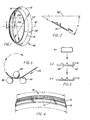
- the shape of a typical combustor liner 40 is shown in Figure 1.
- the conical angle may vary; as defined herein the conical angle is half the included angle of the cone, having a value of the angle P between the cross section of the liner 40 and centerline 42' shown in Figure 2.
- the conical angle of combustors ranges up to 35°. Based on the development to date, the invention herein will be at least useful for conical segments having angles up to 54°.
- the cross sectional area is substantially reduced and of course the length of the piece is accordingly increased substantially.
- the nature of contour rolling may be characterized by this result.
- the lateral dimension of the piece in step A3 is increased by about 20% over the width which the part had in step Al.
- a piece of flat strip shown at step Bl is contour rolled to a flanged channel section 11 as shown at B2.
- the section is axially slit or sawed as shown at B3 to form the section into two separate pieces 12 and 14.
- Piece 12 is used in the succeeding steps while piece 14 may be used to make another assembly.
- the piece 12 is butt welded to the piece 10, along a lengthwise weld joint 16, thereby forming the weldment workpiece 18.
- the thickness Tl of the piece for 12 was made thicker than the thickness T2 of the piece 10, both thicknesses being those measured in the vicinity of the weld joint.
- Filler is added to the weld to make the weld zone essentially of a thickness Tl, as needed to obtain good working of the weld.
- the workpiece 18 is then passed through contour rolls which are shaped to provide a cross sectional shape which is very nearly that desired in the final article (other than it might be modified somewhat in the preferred or optional steps mentioned below).
- this contour rolling step Cl the thickness Tl of piece 12 is substantially reduced to a new thickness T3, preferably slightly less than T2.
- the cross sectional area of the section 10 is reduced only by a relatively small amount, or not at all, while the cross section of the piece 12 is substantially reduced.
- the dimension T2 would be 1.4 mm while the dimension Tl would be 1.65-1.78 mm.
- the thickness T3 would be about 1.27 mm.
- the length Ll would be made relatively about 12% bigger than the length L2. The resultant cone angle will be nominally a reflection of the change in lengths and the width dimension of the workpiece.
- the part is passed through a 3-roll or 4-roll apparatus.
- This is a conventional ring-forming apparatus, as illustrated in Figure 5.
- the roll 20 is progressively moved closer to the fixed rolls 22, 24 during successive passes of the workpiece 26 through the apparatus.
- the 3-roll forming is continued until the opposing ends of the workpiece overlap somewhat.
- the workpiece is removed from the 3-roll machine and the opposing ends are trimmed to the desired circumferential length and then butt welded along an axial joint 28 as shown in Figure 1 to form the cone 40. Because the length Ll is made previously greater than the length L 2, the circular workpiece has the shape of a truncated cone.
- the smaller length of the first piece 10 has resulted in a portion of the cone 40 having an average diameter D10 which is smaller than the average diameter D12 of the portion formed from the piece 12. Accordingly, it can be appreciated that the conical angle will be determined by the relative reductions of the two abutting sections 10, 12 of the workpiece 18. Naturally, if a cone having the reverse taper of that just described was desired, the cross sectional area of the piece 10 would be reduced by a greater amount than the cross sectional area of the piece 12.
- the cone formed by the preceding steps can be stretched or shrunk after welding using a machine having an expandable mandrel or collapsible external die.
- a machine having an expandable mandrel or collapsible external die.
- Stretch forming will usually be employed to increase the diameter by 0.5-5 percent.
- Other shaping and forming operations as are known in the prior art may also be used to further alter the dimensions of the cone shape after the longitudinal ends are joined at the axial weld.
- the weld thickness is preferably made to comply with the thickness of the section which is being reduced, namely thickness Tl of piece 12 in the Figure. This insures that the weld may be properly worked.
- step C3 after the workpiece has been welded to form the structure shown in Figure 1, the liner is heat treated to recrystallize the weld and obtain the desired fatigue properties.
- the cross sectional area of the weld is reduced by at least 20 percent and the weld is heat treated at 1150-1175°C for one hour.
- a piece of flat bar stock shown at Dl can be formed by contour rolling to a first shape illustrated at D2.
- This shape has a first portion 30 and an abutting second portion 32.
- the portion 30 is reduced in cross sectional area while the portion 32 is not reduced as much. This makes a cone with a taper the reverse of that described above.
- the procedure shown in Figure 6 is generally less preferred for two reasons. First, there is undue movement of metal required to make the shape shown at D2. Second, two sets of contour rolls are required, a first set to make the shape shown at D2, and a second set to make the shape shown at D3. In contrast, using the procedure shown in Figure 3, the same set of contour rolls used in the sequence of step C2 may be used for the separate operations shown in the sequences A and B. In the preferred procedure described for the Figure 3 sequence it will be appreciated also that the maximum rolling force and the size of rolling mill required will be reduced from that required by the Figure 6 sequence.
Landscapes
- Engineering & Computer Science (AREA)
- Mechanical Engineering (AREA)
- Butt Welding And Welding Of Specific Article (AREA)
Priority Applications (3)
| Application Number | Priority Date | Filing Date | Title |
|---|---|---|---|
| US06/440,673 US4476194A (en) | 1982-11-10 | 1982-11-10 | Contour forming conical shapes |
| EP84630092A EP0163798B1 (fr) | 1982-11-10 | 1984-06-05 | Formage du contour d'éléments coniques |
| DE8484630092T DE3481590D1 (de) | 1984-06-05 | 1984-06-05 | Konturformen konischer gegenstaende. |
Applications Claiming Priority (2)
| Application Number | Priority Date | Filing Date | Title |
|---|---|---|---|
| US06/440,673 US4476194A (en) | 1982-11-10 | 1982-11-10 | Contour forming conical shapes |
| EP84630092A EP0163798B1 (fr) | 1982-11-10 | 1984-06-05 | Formage du contour d'éléments coniques |
Publications (3)
| Publication Number | Publication Date |
|---|---|
| EP0163798A2 true EP0163798A2 (fr) | 1985-12-11 |
| EP0163798A3 EP0163798A3 (en) | 1987-08-19 |
| EP0163798B1 EP0163798B1 (fr) | 1990-03-14 |
Family
ID=26095639
Family Applications (1)
| Application Number | Title | Priority Date | Filing Date |
|---|---|---|---|
| EP84630092A Expired - Lifetime EP0163798B1 (fr) | 1982-11-10 | 1984-06-05 | Formage du contour d'éléments coniques |
Country Status (2)
| Country | Link |
|---|---|
| US (1) | US4476194A (fr) |
| EP (1) | EP0163798B1 (fr) |
Families Citing this family (12)
| Publication number | Priority date | Publication date | Assignee | Title |
|---|---|---|---|---|
| US4984865A (en) * | 1989-11-17 | 1991-01-15 | Minnesota Mining And Manufacturing Company | Thermoplastic adhesive mounting apparatus and method for an optical fiber connector |
| EP0565406A1 (fr) * | 1992-04-06 | 1993-10-13 | Ishikawajima-Harima Heavy Industries Co., Ltd. | Procédé pour fabriquer un corps en forme d'anneau |
| DE4312122A1 (de) * | 1993-04-14 | 1994-10-20 | Graf & Co Ag | Verfahren zur Herstellung von Profildraht |
| SE508883C2 (sv) * | 1996-05-24 | 1998-11-16 | Ribea Engineering Ab | Valsningsförfarande och maskin för framställning av en konisk mantel av plåt, samt ämne härför |
| TW449509B (en) * | 1998-11-04 | 2001-08-11 | Kawasaki Steel Co | Bending rolls, and pipe formed thereby |
| US20070181267A1 (en) * | 2006-02-04 | 2007-08-09 | Wayne-Dalton Corporation | Sectional door panel |
| US6629415B2 (en) * | 2001-10-27 | 2003-10-07 | General Electric Co. | Methods and apparatus for modeling gas turbine engine combustor liners |
| JP2004202544A (ja) * | 2002-12-25 | 2004-07-22 | Daido Steel Co Ltd | 異形断面をもつ多角形環状体部品の製造方法 |
| US8739511B1 (en) * | 2009-05-05 | 2014-06-03 | Majed Toqan | Can-annular combustor with staged and tangential fuel-air nozzles for use on gas turbine engines |
| FR3025124B1 (fr) * | 2014-08-28 | 2016-09-30 | Snecma | Procede de fabrication de supports d'anneaux d'organe de turbomachine |
| DE112018008202A5 (de) * | 2018-12-14 | 2021-12-02 | Wickeder Westfalenstahl Gmbh | Verfahren zur Herstellung eines Verbundmaterials |
| US11767087B2 (en) * | 2021-06-30 | 2023-09-26 | FabX Industries, Inc. | Automated method for nose cone manufacturing |
Family Cites Families (14)
| Publication number | Priority date | Publication date | Assignee | Title |
|---|---|---|---|---|
| DE493191C (de) * | 1930-03-03 | Hermann Nimmerfall | Walzverfahren zur Herstellung von Kratzendraht | |
| GB736838A (en) * | 1952-09-20 | 1955-09-14 | Wurag Eisen Und Stahlwerke Ag | Improvements in or relating to conveyor worms consisting of a rolled helix and a shaft |
| US2674294A (en) * | 1953-02-19 | 1954-04-06 | Broderna Ekbergs Platslagerifa | Plate bending machine |
| US2815790A (en) * | 1955-06-03 | 1957-12-10 | Thomas L Mayrath | Apparatus for making helical conveyor blades by edgewise bending and squeezing rolls |
| CH409830A (it) * | 1962-11-19 | 1966-03-31 | Boldrini Spa | Macchina per curvare lamiere, in particolare per ottenere pezzi conici |
| DE1452743A1 (de) * | 1963-06-17 | 1969-10-30 | Lagher Gunnar H | Rundmaschine,besonders fuer duennere Bleche |
| CH494604A (de) * | 1968-08-10 | 1970-08-15 | Haeusler Christian | Rundmaschine zur Herstellung eines Konus aus einem kreisringsegmentförmigen Blech |
| US3737979A (en) * | 1971-08-05 | 1973-06-12 | Anaconda American Brass Co | Method of manufacturing longitudinally welded strips of different thicknesses and widths |
| US3978662A (en) * | 1975-04-28 | 1976-09-07 | General Electric Company | Cooling ring construction for combustion chambers |
| US3999416A (en) * | 1975-10-24 | 1976-12-28 | General Electric Company | Cold rolling a contour in metal rings |
| US4077205A (en) * | 1975-12-05 | 1978-03-07 | United Technologies Corporation | Louver construction for liner of gas turbine engine combustor |
| US4195509A (en) * | 1976-06-12 | 1980-04-01 | Hinrichs Gesellschaft Mit Beschrankter Haftung | Device for bending ring segment-shaped plate blanks into conically shaped parts |
| US4206865A (en) * | 1978-11-14 | 1980-06-10 | United Technologies Corporation | Formed louver for burner liner |
| US4380906A (en) * | 1981-01-22 | 1983-04-26 | United Technologies Corporation | Combustion liner cooling scheme |
-
1982
- 1982-11-10 US US06/440,673 patent/US4476194A/en not_active Expired - Lifetime
-
1984
- 1984-06-05 EP EP84630092A patent/EP0163798B1/fr not_active Expired - Lifetime
Also Published As
| Publication number | Publication date |
|---|---|
| US4476194A (en) | 1984-10-09 |
| EP0163798A3 (en) | 1987-08-19 |
| EP0163798B1 (fr) | 1990-03-14 |
Similar Documents
| Publication | Publication Date | Title |
|---|---|---|
| US4476194A (en) | Contour forming conical shapes | |
| US6931906B2 (en) | Method and apparatus for cold forging a trailer hitch receiving housing | |
| CN1253258C (zh) | 矩形截面铝合金环件轧制成形的方法 | |
| JPH11512028A (ja) | 端部の内側に肉厚部を有する圧延管を製作する方法及び装置 | |
| US4220277A (en) | Axle bodies | |
| JP3443528B2 (ja) | 段付及び鍔付環状部材の製造方法 | |
| US3999416A (en) | Cold rolling a contour in metal rings | |
| US2183502A (en) | Explosive shell and method of making the same | |
| RU2461436C1 (ru) | Способ изготовления тонкостенных корпусов переменного сечения | |
| CA1235954A (fr) | Faconnage d'articles en forme de cone | |
| RU2538792C1 (ru) | Способ ротационной вытяжки тонкостенных оболочек с утолщениями | |
| JP2000263105A (ja) | 鉄基分散強化型合金管の製造方法 | |
| RU2131787C1 (ru) | Способ изготовления тонкостенных осесимметричных сосудов | |
| JPH0373376B2 (fr) | ||
| US2843919A (en) | Cold rolling method of making hollow steel blades | |
| JPS63317212A (ja) | 加工性の優れた電縫鋼管の製造方法 | |
| RU2147259C1 (ru) | Способ производства проволоки | |
| Johnson et al. | Rolling of rings | |
| US4515000A (en) | Method for manufacturing consumable welding spacer | |
| SU1759511A1 (ru) | Инструмент дл накатки резьбы | |
| JPH08505325A (ja) | コネクチングロッドの製造方法 | |
| JP2009285665A (ja) | 高温拡管成形性に優れたアルミニウム合金製継目無押出管およびその製造方法 | |
| SU893280A1 (ru) | Способ производства труб | |
| US20100294014A1 (en) | Process and apparatus for producing a hollow body, and hollow body | |
| US3032858A (en) | Manufacture of missile casings |
Legal Events
| Date | Code | Title | Description |
|---|---|---|---|
| PUAI | Public reference made under article 153(3) epc to a published international application that has entered the european phase |
Free format text: ORIGINAL CODE: 0009012 |
|
| AK | Designated contracting states |
Designated state(s): DE FR GB IT SE |
|
| PUAL | Search report despatched |
Free format text: ORIGINAL CODE: 0009013 |
|
| AK | Designated contracting states |
Kind code of ref document: A3 Designated state(s): DE FR GB IT SE |
|
| 17P | Request for examination filed |
Effective date: 19871030 |
|
| 17Q | First examination report despatched |
Effective date: 19881223 |
|
| GRAA | (expected) grant |
Free format text: ORIGINAL CODE: 0009210 |
|
| AK | Designated contracting states |
Kind code of ref document: B1 Designated state(s): DE FR GB IT SE |
|
| ET | Fr: translation filed | ||
| REF | Corresponds to: |
Ref document number: 3481590 Country of ref document: DE Date of ref document: 19900419 |
|
| ITF | It: translation for a ep patent filed | ||
| PLBE | No opposition filed within time limit |
Free format text: ORIGINAL CODE: 0009261 |
|
| STAA | Information on the status of an ep patent application or granted ep patent |
Free format text: STATUS: NO OPPOSITION FILED WITHIN TIME LIMIT |
|
| 26N | No opposition filed | ||
| PGFP | Annual fee paid to national office [announced via postgrant information from national office to epo] |
Ref country code: SE Payment date: 19910521 Year of fee payment: 8 |
|
| ITTA | It: last paid annual fee | ||
| PG25 | Lapsed in a contracting state [announced via postgrant information from national office to epo] |
Ref country code: SE Effective date: 19920606 |
|
| EUG | Se: european patent has lapsed |
Ref document number: 84630092.9 Effective date: 19930109 |
|
| REG | Reference to a national code |
Ref country code: GB Ref legal event code: IF02 |
|
| PGFP | Annual fee paid to national office [announced via postgrant information from national office to epo] |
Ref country code: FR Payment date: 20030618 Year of fee payment: 20 |
|
| PGFP | Annual fee paid to national office [announced via postgrant information from national office to epo] |
Ref country code: GB Payment date: 20030714 Year of fee payment: 20 |
|
| PGFP | Annual fee paid to national office [announced via postgrant information from national office to epo] |
Ref country code: DE Payment date: 20030829 Year of fee payment: 20 |
|
| PG25 | Lapsed in a contracting state [announced via postgrant information from national office to epo] |
Ref country code: GB Free format text: LAPSE BECAUSE OF EXPIRATION OF PROTECTION Effective date: 20040604 |
|
| REG | Reference to a national code |
Ref country code: GB Ref legal event code: PE20 |