EP0163859A2 - Véhicule à ordures comportant une benne collectrice construite sous la forme d'un récipient interchangeable - Google Patents
Véhicule à ordures comportant une benne collectrice construite sous la forme d'un récipient interchangeable Download PDFInfo
- Publication number
- EP0163859A2 EP0163859A2 EP85104353A EP85104353A EP0163859A2 EP 0163859 A2 EP0163859 A2 EP 0163859A2 EP 85104353 A EP85104353 A EP 85104353A EP 85104353 A EP85104353 A EP 85104353A EP 0163859 A2 EP0163859 A2 EP 0163859A2
- Authority
- EP
- European Patent Office
- Prior art keywords
- collection vehicle
- cab
- garbage collection
- refuse
- container
- Prior art date
- Legal status (The legal status is an assumption and is not a legal conclusion. Google has not performed a legal analysis and makes no representation as to the accuracy of the status listed.)
- Granted
Links
Images




Classifications
-
- B—PERFORMING OPERATIONS; TRANSPORTING
- B65—CONVEYING; PACKING; STORING; HANDLING THIN OR FILAMENTARY MATERIAL
- B65F—GATHERING OR REMOVAL OF DOMESTIC OR LIKE REFUSE
- B65F1/00—Refuse receptacles; Accessories therefor
- B65F1/12—Refuse receptacles; Accessories therefor with devices facilitating emptying
- B65F1/122—Features allowing the receptacle to be lifted and subsequently tipped by associated means on a vehicle
-
- B—PERFORMING OPERATIONS; TRANSPORTING
- B65—CONVEYING; PACKING; STORING; HANDLING THIN OR FILAMENTARY MATERIAL
- B65F—GATHERING OR REMOVAL OF DOMESTIC OR LIKE REFUSE
- B65F3/00—Vehicles particularly adapted for collecting refuse
- B65F3/14—Vehicles particularly adapted for collecting refuse with devices for charging, distributing or compressing refuse in the interior of the tank of a refuse vehicle
- B65F3/143—Means facilitating the separation of the charging, distributing or compressing devices from the tank of refuse vehicles
-
- B—PERFORMING OPERATIONS; TRANSPORTING
- B65—CONVEYING; PACKING; STORING; HANDLING THIN OR FILAMENTARY MATERIAL
- B65F—GATHERING OR REMOVAL OF DOMESTIC OR LIKE REFUSE
- B65F3/00—Vehicles particularly adapted for collecting refuse
- B65F3/14—Vehicles particularly adapted for collecting refuse with devices for charging, distributing or compressing refuse in the interior of the tank of a refuse vehicle
- B65F3/20—Vehicles particularly adapted for collecting refuse with devices for charging, distributing or compressing refuse in the interior of the tank of a refuse vehicle with charging pistons, plates, or the like
- B65F3/201—Vehicles particularly adapted for collecting refuse with devices for charging, distributing or compressing refuse in the interior of the tank of a refuse vehicle with charging pistons, plates, or the like the charging pistons, plates or the like moving rectilinearly
-
- B—PERFORMING OPERATIONS; TRANSPORTING
- B65—CONVEYING; PACKING; STORING; HANDLING THIN OR FILAMENTARY MATERIAL
- B65F—GATHERING OR REMOVAL OF DOMESTIC OR LIKE REFUSE
- B65F3/00—Vehicles particularly adapted for collecting refuse
- B65F2003/006—Constructional features relating to the tank of the refuse vehicle
- B65F2003/008—Constructional features relating to the tank of the refuse vehicle interchangeable
-
- B—PERFORMING OPERATIONS; TRANSPORTING
- B65—CONVEYING; PACKING; STORING; HANDLING THIN OR FILAMENTARY MATERIAL
- B65F—GATHERING OR REMOVAL OF DOMESTIC OR LIKE REFUSE
- B65F3/00—Vehicles particularly adapted for collecting refuse
- B65F3/02—Vehicles particularly adapted for collecting refuse with means for discharging refuse receptacles thereinto
- B65F2003/0263—Constructional features relating to discharging means
- B65F2003/0273—Constructional features relating to discharging means capable of rotating around a vertical axis
-
- B—PERFORMING OPERATIONS; TRANSPORTING
- B65—CONVEYING; PACKING; STORING; HANDLING THIN OR FILAMENTARY MATERIAL
- B65F—GATHERING OR REMOVAL OF DOMESTIC OR LIKE REFUSE
- B65F3/00—Vehicles particularly adapted for collecting refuse
- B65F3/02—Vehicles particularly adapted for collecting refuse with means for discharging refuse receptacles thereinto
- B65F2003/0263—Constructional features relating to discharging means
- B65F2003/0279—Constructional features relating to discharging means the discharging means mounted at the front of the vehicle
-
- Y—GENERAL TAGGING OF NEW TECHNOLOGICAL DEVELOPMENTS; GENERAL TAGGING OF CROSS-SECTIONAL TECHNOLOGIES SPANNING OVER SEVERAL SECTIONS OF THE IPC; TECHNICAL SUBJECTS COVERED BY FORMER USPC CROSS-REFERENCE ART COLLECTIONS [XRACs] AND DIGESTS
- Y10—TECHNICAL SUBJECTS COVERED BY FORMER USPC
- Y10S—TECHNICAL SUBJECTS COVERED BY FORMER USPC CROSS-REFERENCE ART COLLECTIONS [XRACs] AND DIGESTS
- Y10S220/00—Receptacles
- Y10S220/908—Trash container
Definitions
- the invention relates to a motor-driven refuse collection vehicle with a container designed as an interchangeable container with detachable couplings for receiving the refuse, with a discharge unit firmly connected to it, consisting of a pouring opening arranged in the front area of the vehicle and a lifting and tipping device for receiving and emptying refuse containers in the pouring opening of a receiving space, and with a conveying and pressing device for transporting the garbage emptied into the pouring opening into the container through its filling opening provided with a closure device.
- a refuse collection vehicle of this type is known from DE-PS 24 58 905 and is used in the context of an interchangeable container refuse collection system for collecting refuse and for transporting the refill-filled containers to a central container handling point, where the filled containers are exchanged for empty ones and by the filled containers are transported to the landfill by special vehicles.
- the garbage collection vehicle is specially adapted for collecting the garbage and can do this task economically, since it is generally not used to transport the filled containers to the landfills.
- the conveying devices which connect the pouring opening with the filling opening of the container are passed under the driver's cab, this is arranged relatively high, so that the driver does not have a good view of the street and the refuse containers provided to the side thereof.
- the garbage containers to be emptied must be placed or driven in front of the front of the garbage collection vehicle so that they can be gripped and tilted by the lifting and tipping device.
- the object of the invention is therefore to improve the refuse collection vehicle of the type specified in that the refuse containers provided can simply be coupled to the lifting and tipping device and emptied into the pouring opening, so that the collection work can also be carried out by the driver alone.
- this object is achieved in that the pouring opening of the dumping unit, partly above the driver's cab of the refuse collection vehicle and partly between this and the container, is located in the area behind and above the driver's cab, and in that the lifting and tipping device has at least one about a transverse axis of the dumping unit or the chassis has pivotable lifting arm which carries at its free end a base rail parallel to the transverse axis, which can be pivoted between its receiving area approximately below and in front of the driver's cab and its dumping area above and behind the driver's cab and with extendable and / or pivotable devices for gripping or coupling provided waste container is provided.
- the driver's cab can be arranged in such a way that the driver has an optimal view of the street and the garbage containers provided to the side of it.
- the driver can carry out the collection work himself without any additional assistants and without having to leave the driver's seat, since the lifting and tilting device is provided with a device that can be controlled from the driver's seat for gripping or coupling to the waste containers provided, so that this can be done without any special manual work pick up, tilt and empty and let set down again.
- the garbage collection vehicle according to the invention therefore not only facilitates the collection work, it is also substantially rationalized in that it can be carried out by only one person with a high degree of utilization of the vehicle.
- the refuse collection vehicle according to the invention expediently has a short center distance to increase its maneuverability.
- the driver has a particularly good view of the street and the waste containers provided if the driver's cab is located as low as possible in front of the front axle.
- the refuse collection vehicle is expediently provided with left-hand and right-hand drive, so that the driver controls the left control in normal road traffic, for example when driving to the central container collection point or to a nearby landfill, and during the collection work to empty the right-hand road the right container can use the waste container provided.
- the lifting arm consists of two U-shaped brackets with shorter and longer legs arranged on both sides of the driver's cab, that the swivel axis is in the area of the shorter legs is located and that at the ends of the longer legs the base rail-carrying coupling pieces are articulated with their one ends, the other ends of which are connected to the dumping unit or dsm refuse vehicle via coupling rods which are articulated with levers mounted in the inner end region of the legs the rail, when it is pivoted up to the upper front area of the driver's cab, performs essentially no rotation relative to it and over the remaining pivoting path to the pouring opening, an accelerated rotary movement.
- This kinematics of the lifting and tipping device ensures that there is essentially no rotation of the waste container during most of the lifting path, so that no waste can fall out of it.
- the accelerated rotary movement in the last part of the way to the dump opening in connection with the abutment of the lifting arms or the garbage container against a stop or with a delayed braking movement in the end region of the pouring movement or even with an accelerated retraction movement of the garbage container means that the garbage from it as it were is thrown into the pouring opening.
- a handlebar is pivotally mounted on the base rail about a vertical axis, which carries at its free end the receiving claw for the garbage container that this between their pivoted-out position and their center position against the base rail can be pivoted.
- the receiving claw expediently consists of an isosceles triangular member with its tip pointing upwards. Which is pivotally mounted about a vertical bolt of the coupling piece. Such a claw can be inserted self-centering into a correspondingly shaped receiving groove of the waste container.
- the receiving claw is axially displaceably guided against the spring force on the vertical bolt and is blocked relative to the latter in its pressed-down position. While the receiving claw for insertion into the receiving groove centers itself against the corresponding container wall, the receiving claw is locked under the weight of the coupled waste container relative to the bolt carrying it, so that the waste container is connected to the receiving rail of the lifting and tipping device during tilting a locking bar is set.
- control arm and the auxiliary control arm or the main control arm are mounted solely on a support or a hollow profile which is displaceably mounted on the base rail over at least one end thereof.
- the delivery and pressing chamber is provided below the receiving space, in which a stamp with a cross-section corresponding to the chamber is guided to and fro by lateral toggle levers that the Knee levers are articulated on the back of the press ram and in the area of the rear wall of the chamber and that one end of articulated hydraulic pressure-piston-cylinder units are articulated on the knee joints of the knee levers, the other ends of which are in the area of the fixed joints of the other toggle levers are articulated.
- the garbage can first be pushed into the container at a higher speed, the press ram acting on the garbage at a higher speed in the last part of its insertion movement at a lower speed. It is also particularly advantageous that the toggle-lever pressure medium piston-cylinder system which moves the ram has only a very small axial length in the retracted state, which favors a compact, economical construction.
- a subframe lying on this is pivotally connected to the main frame of the chassis, that the container is releasably locked to the subframe, that the.
- Subframe is pivotable about bolts which are slidably guided in elongated holes in the rear area of the main frame that the subframe is provided at its front end with a nose which engages under a stop plate of the main frame in the pushed forward state of the subframe and that auxiliary and Main frame are connected by an inclined hydraulic pressure medium piston-cylinder unit such that the nose is lifted from the overlapping stop before the subframe is tilted.
- This configuration enables the container to be emptied in a conventional manner by pivoting the subframe.
- the container can be detached from the subframe by means of quick coupling devices, so that the filled containers can be quickly and easily exchanged for empty containers as part of the swap body waste collection system.
- the refuse collection vehicle of the swap body refuse collection system consists of a truck with a short center distance in order to give the vehicle good maneuverability when collecting refuse.
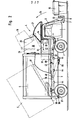
- the driver's cab 1 is fastened in front of the front axle 2 to the base frame 3 of the chassis, so that it projects with its lower edge into the area of the plane of the wheel axles or even lower and gives the driver a good view of waste containers standing next to the road.
- the garbage collection vehicle is provided in the manner shown in FIG. 1 with two steering wheels for left and right steering, so that the driver can use left steering in normal road traffic and sit on the right side of the vehicle to collect the garbage on which the garbage containers are provided .
- the dump unit 4 is connected to the vehicle frame 3 on the chassis in such a way that it is arranged between the driver's cab 1 and the container 5 and extends over the driver's cab 1.
- the lifting and tilting device consists of two U-shaped swivel arms 6, 6 'arranged on both sides of the driver's cab, the shorter legs of which are pivotally mounted about an axis 46 arranged behind the driver's cab in the lower region of the dumping unit 4 or on the chassis. At the free ends of the longer legs, the one ends of coupling pieces 7, 7 'are articulated through a base rail 8 parallel to the wheel axles are interconnected.
- the swivel or lifting arms 6, 6 ' are designed in the form of a bow in such a way that their short legs are in the lowered state behind the rear wall of the cab and their longer front legs are in the front side area of the cab, the legs being connected to one another by webs 10 which are above the side doors of the cab are located so that neither the view nor the opening and closing of the cab doors are obstructed by the lifting arms.
- the garbage containers 19 are provided in the upper edge region of their opening side with a reinforcing profile 20, which on its lower edge has an undercut complementary to the wedge-shaped gripping edge 16 of the gripping claw 15,
- the container 19 can be coupled to the lifting and tilting device.
- the gripping claw 15 is pivoted into its lifting and tilting position, in which it rests centrally on the profile tube 11.
- a bolt 22 projecting therefrom is fastened, the upper angled nose 23 of which engages over the upper container edge or the upper edge of the profiled reinforcement 20 provided with the receptacle 21 and locks the container with the lifting and tilting device.
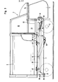
- the container 19 is lifted in the direction shown by arrow 24 in FIG. 2 and emptied into the pouring opening 25 of the pouring unit 4.
- the container 19 is first raised in such a way that it initially remains in its essentially vertical position and garbage cannot fall out. Only shortly before the pouring opening 25, the base rail 8 performs an accelerated rotation, through which the lid 26 of the container is opened and the waste is thrown into the pouring opening, as it were, by the lifting arms or the container hitting a stop or the lifting arms performing a return movement .
- the coupling of the rubbish bins on the right-hand side of the street for emptying to the lifting and tipping device, as well as lifting and tipping, can be done using suitable controls Carry out directions from the driver's seat, so that the collection of the garbage can only be done by the driver of the garbage truck, without this having to leave the driver's seat and do strenuous or dirty work.
- a ram 27 consisting of a curved sheet metal leads to the pouring opening 25.
- This ramp is curved about a transverse axis of the refuse collection vehicle in such a way that when the container 19 is tilted it is swept a short distance from the base rail 8 or the profile tube 11.
- Profile tube 11 are provided with a suitable scraper edge so that garbage falling out of the waste container 19 is taken along prematurely and pushed into the pouring opening 25.
- the receiving space 30 for the poured rubbish adjoins the pouring opening 25 delimited by the side walls 28, 29.
- the lower part 31 of this receiving space forms a delivery chamber in which the ram 32 can be moved back and forth in the direction of the double arrow 33.
- the press punch 32 which is shown widened only for the purpose of illustration, is provided with an upper end plate 34 which, when the press punch 32 is pushed forward, separates the conveying and pressing chamber 31 from the upper part of the receiving space 30. If the ram 32 is retracted, the end plate 34 is pushed in the manner shown in FIG. 2 in a guide over the cab 1, so that 30 garbage can fall into the conveyor and press chamber 31 from the upper part of the receiving space.
- the garbage is inserted into the garbage 5 through an opening of the container 5.
- the opening of the container 5 can be closed by slides, not shown, which by means of corresponding pawls or coupling devices
- Pressure medium piston cylinder units are movable, which are part of the pouring unit 4.
- the frame 36 is first moved backward on the base frame 3 by actuating the pressure-piston-cylinder unit until the bolt 37 abuts the end of the elongated hole 39 in the manner shown in FIG. 2.
- the nose 87 has been pushed free by the leg of the angular profile 88 covering it, so that the pivot frame 36 can be pivoted in the manner shown in FIG. 2 for emptying the container.
- the container 5 is provided at its front end with a locking bolt 41, behind which a locking hook 42 of the pouring unit 4 engages.
- the container 5 is locked on the swivel frame 36 by locking devices 43 and centered by side jaws 44. After loosening the locks 41, 42, 43, the container 5 can be lifted from the refuse collection vehicle after closing its fill opening and made available for transport by suitable special vehicles to the landfills.
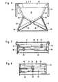
- the profile tube 11 as can be seen from FIG. 5, is provided in its end region on its rear side with an elongated slot-like slot 47, so that it can be extended to the right via the coupling piece 7. There is the possibility of moving the profile tube 11 to the right by about 1.20 m via the coupling piece 7.
- the cylinder 48 of a hydraulic piston-cylinder unit is fastened in the base rail 8 consisting of a box profile on the left-hand side as viewed in the direction of travel. The piston rod of this cylinder is on that extendable end of the profile tube 11 attached.
- the upper and lower main links 12, 12 ' are pivotally mounted on the profile tube 11 about the bolts 50, 50'.
- the outer end of the link 12 is pivotally mounted on a bolt 51 which is fixedly connected to the coupling piece 14.
- the bolt 51 is provided with a bore in which the bolt 52 carrying the gripping claw 15 is guided so as to be longitudinally displaceable to a limited extent.
- a spring 53 which surrounds the bolt 52 and is supported with its lower end on the lower main link 12 'and with its upper end on a stop 54 connected to the bolt 52, the bolt and thus the gripping claw 15 is in the unloaded state in System held to a stop, not shown.
- the bush-like hinge pin 51 for the main link 12 has at its upper end opposite grooves, the flanks of which are connected to one another by rounded parts.
- complementary lugs 55 are connected to the upper end of the claw 15 pivotally mounted pin 52, which are pressed down against the force of the spring 53 when the gripping claw 15 is loaded by a waste container and thereby engage in the grooves and the gripping claw fix relative to the coupling piece 14.
- the gripping claw In the unloaded state, as can be seen from FIG. 4, the gripping claw can be pivoted 45 ° to the left and to the right between stops, not shown, relative to the coupling piece 14. To pick up a waste container, the gripping claw 15 therefore only needs to be pivoted against the front side of the waste container provided with the receiving groove 21.
- the auxiliary link 13 is articulated to the coupling piece 14 in the manner shown in FIG. 4.
- the articulation points of the auxiliary link 13 on the coupling piece 14 and the profile tube 11 are selected such that the gripping claw 15 can be pivoted between its central position, in which it lies close to the profile tube 11, and its pivoted-out position, which can be seen in FIG. 4.
- the locking rod 22 is connected in the middle to the profile tube 11.
- the container edge or the profile strip 20 provided with the receiving groove 21 is clamped and fixed between the rounded tip of the gripping claw 15 and the overlapping tongue 23 of the locking rod 22.
- the gripping claw 15 consists, as can best be seen from FIG. 5, of a triangular shaped piece, the base of which is connected to a profiled lower cross member 60.
- the tip of the isosceles triangle is rounded and the gripping edges 16, which are formed by the triangle sides and the tip, are sloping towards the inside.
- the container 19 is of a conventional design and has the pivot axis for the hinged lid 26 on its side opposite the receiving profile 20.
- Containers of different sizes can be provided with the same receiving profile 20, so that containers of different sizes can be gripped and tilted with the gripping claw 15 of the lifting and tilting device.
- Fig. Sb for example, a larger container and a smaller container are shown, which has the usual household size.
- the press die 32 is adapted to the cross-sectional shape of the chamber 31 and has a rectangular shape. It is connected to the cover plate 34, which is guided in lateral guides 71, 72.
- the cover plate 34 closes the delivery and pressing chamber 31 with the press ram 32, so that the toggle mechanism and the piston-cylinder units are not contaminated by the falling garbage. In its retracted position, the toggle-piston-cylinder system only occupies a short axial position, so that a compact design is possible.
- the kinematics of the handlebar-lever system of the lifting arms 6, 6 ' can be seen in FIG. 9, in which the container 19 is shown in five different positions between its receiving position and its tilting position.
- the shorter leg 75 of the The lifting arm is fixed to the frame about the axis 46.
- the approximately triangular Hebelplat t s 78, 79 so pivotally mounted that they project beyond the angular ranges of the lifting arms toward the outside.
- the coupling rods 9, 80, 81 are articulated to the lever plates in the corner regions of the base.
- the coupling rod 80 runs approximately parallel to the web 10 and connects the two lever plates 78, 79 in the manner shown.
- the coupling rod 9 runs approximately parallel to the longer leg 82 and is articulated on the coupling piece 14 of the base rail.
- the inner coupling rod 81 is articulated at its outer end to the lever plate 78 and at its inner end on the bolt 83 to the frame.
- the desired stroke and swivel path of the container 19 can be seen from the container positions 1 to 5.
- the hinge axis 84 of the container cover is located on the container side opposite the coupling elements, so that the cover opens automatically in the region of position 5 of the container when it is tilted.
Landscapes
- Engineering & Computer Science (AREA)
- Mechanical Engineering (AREA)
- Refuse-Collection Vehicles (AREA)
- Forklifts And Lifting Vehicles (AREA)
- Refuse Collection And Transfer (AREA)
- Accommodation For Nursing Or Treatment Tables (AREA)
- Lubrication Details And Ventilation Of Internal Combustion Engines (AREA)
Priority Applications (2)
| Application Number | Priority Date | Filing Date | Title |
|---|---|---|---|
| AT85104353T ATE48263T1 (de) | 1984-05-29 | 1985-04-10 | Motorgetriebenes muellsammelfahrzeug mit einem als wechselbehaelter ausgebildeten container. |
| DE8787102928T DE3568021D1 (en) | 1984-05-29 | 1985-04-10 | Tipping mechanism for a refuse-collecting vehicle |
Applications Claiming Priority (2)
| Application Number | Priority Date | Filing Date | Title |
|---|---|---|---|
| DE19843420058 DE3420058A1 (de) | 1984-05-29 | 1984-05-29 | Motorgetriebenes muellsammelfahrzeug mit als wechselbehaelter ausgebildeten containern |
| DE3420058 | 1984-05-29 |
Related Child Applications (1)
| Application Number | Title | Priority Date | Filing Date |
|---|---|---|---|
| EP87102928.6 Division-Into | 1985-04-10 |
Publications (3)
| Publication Number | Publication Date |
|---|---|
| EP0163859A2 true EP0163859A2 (fr) | 1985-12-11 |
| EP0163859A3 EP0163859A3 (en) | 1987-07-15 |
| EP0163859B1 EP0163859B1 (fr) | 1989-11-29 |
Family
ID=6237150
Family Applications (2)
| Application Number | Title | Priority Date | Filing Date |
|---|---|---|---|
| EP87102928A Expired EP0235784B1 (fr) | 1984-05-29 | 1985-04-10 | Dispositif de culbutage pour un véhicule à ordures |
| EP85104353A Expired EP0163859B1 (fr) | 1984-05-29 | 1985-04-10 | Véhicule à ordures comportant une benne collectrice construite sous la forme d'un récipient interchangeable |
Family Applications Before (1)
| Application Number | Title | Priority Date | Filing Date |
|---|---|---|---|
| EP87102928A Expired EP0235784B1 (fr) | 1984-05-29 | 1985-04-10 | Dispositif de culbutage pour un véhicule à ordures |
Country Status (4)
| Country | Link |
|---|---|
| US (3) | US4715767A (fr) |
| EP (2) | EP0235784B1 (fr) |
| AT (2) | ATE48263T1 (fr) |
| DE (3) | DE3420058A1 (fr) |
Cited By (7)
| Publication number | Priority date | Publication date | Assignee | Title |
|---|---|---|---|---|
| DE3631914C1 (de) * | 1986-05-06 | 1987-09-10 | Edelhoff Polytechnik | Muellsammelfahrzeug |
| DE3615998A1 (de) * | 1986-05-13 | 1987-11-26 | Kraus & Schoellhorn Karosserie | Muellsammelfahrzeug |
| DE3804090A1 (de) * | 1988-02-10 | 1989-08-24 | Edelhoff Polytechnik | Muellsammelfahrzeug |
| WO1996022930A1 (fr) * | 1995-01-23 | 1996-08-01 | Multilift Oy | Procede de manutention des detritus, systeme de manutention des detritus et conteneur a detritus |
| EP0795494A1 (fr) * | 1996-03-14 | 1997-09-17 | Edelhoff M.S.T.S. Gmbh | Véhicule pour la collecte des ordures |
| EP0860380A1 (fr) * | 1997-02-19 | 1998-08-26 | Max Aicher GmbH Entsorgungstechnik | Véhicule pour le ramassage des ordures |
| CN104016049A (zh) * | 2014-05-30 | 2014-09-03 | 徐州徐工随车起重机有限公司 | 一种侧装压缩式垃圾车 |
Families Citing this family (109)
| Publication number | Priority date | Publication date | Assignee | Title |
|---|---|---|---|---|
| DE3420058A1 (de) * | 1984-05-29 | 1985-12-05 | Edelhoff Polytechnik GmbH & Co, 5860 Iserlohn | Motorgetriebenes muellsammelfahrzeug mit als wechselbehaelter ausgebildeten containern |
| EP0185382B1 (fr) * | 1984-12-21 | 1989-10-18 | Edelhoff M.S.T.S. Gmbh | Adaptateur pour poubelles |
| DE8519096U1 (de) * | 1985-07-01 | 1985-11-07 | Edelhoff Polytechnik GmbH & Co, 5860 Iserlohn | Müllbehälter |
| DE3684538D1 (de) * | 1985-08-13 | 1992-04-30 | Edelhoff Polytechnik | System zur bestimming der lage eines objekts relativ zu einer handhabungseinrichtung. |
| EP0218965B1 (fr) * | 1985-10-02 | 1990-12-05 | Edelhoff M.S.T.S. Gmbh | Véhicule à ordures automobile |
| EP0230663B1 (fr) * | 1986-01-31 | 1990-11-07 | VALLE TEIRO S.r.l. | Dispositif pour soulever, basculer et décharger des récipients à ordures dans un véhicule à ordures, comportant une pièce coulissante, un ou plusieurs bras de levier et une tête de préhension triangulaire oscillante et mobile transversalement |
| EP0235824B1 (fr) * | 1986-03-07 | 1991-01-16 | EDELHOFF POLYTECHNIK GMBH & CO. | Récipient à ordures |
| DE3636037A1 (de) * | 1986-10-23 | 1988-04-28 | Bock Norman | Verfahren zum aufnehmen und absetzen eines hohl-behaelters, wie silo, container oder dergleichen, auf bzw. von einem fahrzeug mit wechselgeraet, wechselgeraet zur durchfuehrung des verfahrens sowie bei der durchfuehrung des verfahrens verwendbarer behaelter |
| DE3639861A1 (de) * | 1986-11-21 | 1988-06-01 | Zoeller Kipper | Hubkipp- oder kippvorrichtung zum entleeren von behaeltern, insbesondere muellbehaeltern, in einen sammelbehaelter |
| US5458452A (en) * | 1987-05-21 | 1995-10-17 | Pellegrini; Louis A. | Vehicle and method for collecting recyclable waste material |
| US5116184A (en) * | 1989-10-19 | 1992-05-26 | Pellegrini Louis A | Vehicle and method for collecting recyclable waste materials |
| DE3720442A1 (de) * | 1987-06-19 | 1989-01-05 | Edelhoff Polytechnik | Muellsammelfahrzeug |
| ES2040318T3 (es) * | 1987-12-22 | 1993-10-16 | Barmag Ag | Manipulador. |
| US4811660A (en) * | 1988-01-05 | 1989-03-14 | Marathon Corporation | Mechanical lock-in device for a front loader compaction assembly |
| US5261553A (en) * | 1988-01-07 | 1993-11-16 | Jay Mueller | Fastening device for container liners |
| DE3821843A1 (de) * | 1988-04-08 | 1989-10-26 | Schoerling Waggonbau | Muellsammelfahrzeug |
| EP0336003A3 (fr) * | 1988-04-08 | 1990-06-20 | SCHÖRLING GMBH & CO. WAGGONBAU | Véhicule à ordures |
| US5074737A (en) * | 1990-01-16 | 1991-12-24 | Pellegrini Louis A | Trash collection vehicle |
| DE3830681A1 (de) * | 1988-04-08 | 1989-10-26 | Schoerling Waggonbau | Muellsammelfahrzeug |
| US4909564A (en) * | 1988-04-29 | 1990-03-20 | Peabody International Corporation | Front loading refuse truck body |
| DE3825184A1 (de) * | 1988-06-27 | 1989-12-28 | Edelhoff Polytechnik | Quaderfoermiger container |
| EP0348874B1 (fr) * | 1988-06-27 | 1993-05-05 | EDELHOFF POLYTECHNIK GMBH & CO. | Conteneur carré |
| DE3831406A1 (de) * | 1988-08-29 | 1990-03-01 | Edelhoff Polytechnik | Muellbehaelter |
| DE3835748C1 (fr) * | 1988-10-20 | 1989-10-12 | Kellner Ag, Steinhausen, Ch | |
| US5251779A (en) * | 1989-01-25 | 1993-10-12 | Stefan Schmidt | Trash container |
| DE3902177C1 (fr) * | 1989-01-25 | 1990-06-21 | Edelhoff Polytechnik Gmbh & Co, 5860 Iserlohn, De | |
| US5169195A (en) * | 1989-01-25 | 1992-12-08 | Edelhoff Polytechnik Gmbh & Co. | Container handling equipment |
| DE3927867A1 (de) * | 1989-08-23 | 1991-02-28 | Edelhoff Polytechnik | Lastkraftwagen zum aufnehmen, absetzen und transport von mit diesem kuppelbaren behaeltern, vorzugsweise muellsammelfahrzeug mit wechselbehaeltern |
| US5078560A (en) * | 1989-11-22 | 1992-01-07 | Intermodal Technologies, Inc. | Bulk materials transportation system |
| US5230434A (en) * | 1989-11-22 | 1993-07-27 | Intermodal Technologies, Inc. | Container for bulk materials transportation system |
| US5238357A (en) * | 1989-11-22 | 1993-08-24 | Intermodal Technologies, Inc. | Bulk materials transportation system |
| US5256023A (en) * | 1989-11-22 | 1993-10-26 | Intermodal Technologies, Inc. | Roll-out forklift for bulk materials transportation system |
| DE4009060A1 (de) * | 1990-03-21 | 1991-09-26 | Schaefer Gmbh Fritz | Muell-entsorgungssystem |
| DE4013433A1 (de) * | 1990-04-26 | 1991-10-31 | Edelhoff Polytechnik | Muellsammelfahrzeug |
| US5215423A (en) * | 1990-09-21 | 1993-06-01 | Edelhoff Polytechnik Gmbh & Co. | System for determining the spatial position of an object by means of a video optical sensor |
| US5137414A (en) * | 1990-11-29 | 1992-08-11 | Sloan Wesley S | Translatable tilt-bed trailer apparatus |
| US5178062A (en) * | 1990-12-19 | 1993-01-12 | Marathon Equipment Company | Apparatus for compressing waste materials |
| DE4102064A1 (de) * | 1991-01-24 | 1992-08-13 | Edelhoff Polytechnik | Muellsammelfahrzeug mit einer hubkippvorrichtung zur aufnahme und zum entleeren von muellbehaeltern in eine einschuettoeffnung |
| US5203669A (en) * | 1991-04-25 | 1993-04-20 | Waste Management Of North America, Inc. | Garbage truck |
| DE4128415A1 (de) * | 1991-08-27 | 1993-03-04 | Edelhoff Polytechnik | Anbausatz zum containerhandling und presse zum verdichten des containerinhalts |
| FR2681650B1 (fr) * | 1991-09-20 | 1993-11-19 | Crcm | Systeme d'actionnement d'un bouclier pousseur notamment pour compacteur de dechets. |
| DE4203119C2 (de) * | 1992-02-04 | 1994-06-23 | Edelhoff Polytechnik | Aufnahmevorrichtung für Müllsammelfahrzeuge |
| CA2129629C (fr) * | 1992-02-10 | 2003-12-02 | Idwall Charles Richards | Camion collecteur de dechets a chargement lateral |
| RU2119883C1 (ru) * | 1992-02-12 | 1998-10-10 | Эдгар Георг | Транспортное средство для приема и транспортировки мусора |
| DE4204062A1 (de) * | 1992-02-12 | 1993-08-19 | Edgar Georg | Fahrzeug zum aufnehmen und transportieren von abfallstoffen |
| US5330071A (en) * | 1992-08-14 | 1994-07-19 | Waste Management Of North America, Inc. | Plastic refuse container |
| US5281074A (en) * | 1992-10-08 | 1994-01-25 | David Mashuda | Truck body |
| DE4243011C1 (de) * | 1992-12-18 | 1994-06-23 | Schoerling Fahrzeugbau Haeusli | Müllsammelfahrzeug |
| GB9315805D0 (en) * | 1993-07-30 | 1993-09-15 | Boughton T T Sons Ltd | Improved refuse handling system |
| US5890865A (en) * | 1993-09-09 | 1999-04-06 | Mcclain E-Z Pack | Automated low profile refuse vehicle |
| US5954470A (en) * | 1993-09-09 | 1999-09-21 | Galion Solid Waste Equipment Co, Inc. | Compacting system and refuse vehicle |
| US5601392A (en) * | 1993-09-09 | 1997-02-11 | Galion Solid Waste Eqt., Inc. | Front-side lifting and loading apparatus |
| DE9407869U1 (de) * | 1994-05-13 | 1995-09-14 | Georg, Edgar, 57638 Neitersen | Müllsammelfahrzeug |
| DE9415505U1 (de) * | 1994-08-26 | 1995-01-05 | Otto Lift-Systeme GmbH, 50968 Köln | Einrichtung zum Entleeren von Müllbehältern in ein Müllsammelfahrzeug hinein |
| DE4430260C2 (de) * | 1994-08-26 | 2003-01-02 | Otto Lift Systeme Gmbh | Einrichtung zum Entleeren von Müllbehältern in ein Müllsammelfahrzeug hinein |
| US5562390A (en) * | 1995-01-24 | 1996-10-08 | Mcneilus Truck And Manufacturing, Inc. | Detachable truck body and handling mechanism |
| USD370875S (en) | 1995-03-06 | 1996-06-18 | Mcneilus Truck And Manufacturing, Inc. | Refuse hauling vehicle |
| US6059511A (en) * | 1995-03-07 | 2000-05-09 | Toccoa Metal Technologies, Inc. | Residential front loading refuse collection vehicle |
| US5802693A (en) * | 1995-03-10 | 1998-09-08 | Compagnie Plastic Omnium | Method of fabricating a refuse container |
| US5931628A (en) * | 1995-03-28 | 1999-08-03 | Mcneilus Truck And Manufacturing, Inc. | Manual/automated side loader |
| CA2170215C (fr) * | 1995-03-28 | 2001-12-04 | Ronald E. Christenson | Manutentionneur de bacs basculants |
| AU692688B2 (en) * | 1995-04-03 | 1998-06-11 | James Caruso | Mobile skip bin handling vehicle improvements |
| AUPN209995A0 (en) * | 1995-04-03 | 1995-04-27 | Papalia, John | Mobile skip bin loader |
| US5797715A (en) * | 1995-06-08 | 1998-08-25 | Mcneilus Truck And Manufacturing, Inc. | Collection apparatus |
| DE29520278U1 (de) * | 1995-12-21 | 1997-04-17 | Georg, Edgar, 57638 Neitersen | Containerfahrzeug mit Ladeeinrichtung |
| DE29605807U1 (de) * | 1996-03-28 | 1996-07-04 | Edelhoff M.S.T.S. Gmbh, 58640 Iserlohn | Müllsammelfahrzeug |
| US5829944A (en) * | 1996-06-20 | 1998-11-03 | Kann Manufacturing Corporation | Multi-side refuse receptacle collection assembly |
| US5833428A (en) * | 1996-06-20 | 1998-11-10 | Kann Manufacturing Corporation | Refuse receptacle collection assembly |
| US5785487A (en) * | 1997-01-27 | 1998-07-28 | Mcneilus Truck And Manufacturing, Inc. | Push out ejection systems for refuse truck |
| US5857822A (en) * | 1997-03-31 | 1999-01-12 | Mcneilus Truck And Manufacturing, Inc. | Ejection and compacting system for refuse truck |
| WO1998050295A1 (fr) * | 1997-05-09 | 1998-11-12 | Kosti Shirvanian | Camion a ordures |
| US5919026A (en) * | 1997-06-02 | 1999-07-06 | Kann Manufacturing Corporation | Carry can discharge floor |
| US6012892A (en) * | 1997-10-16 | 2000-01-11 | The Heil Co | Refuse collection vehicle |
| DE19808418A1 (de) * | 1998-02-28 | 1999-09-09 | Schwelling | Antriebsvorrichtung für die Preßplatte von Abfall-Ballenpressen |
| US6264528B1 (en) | 1998-03-17 | 2001-07-24 | Steve Doan | Remote-controlled toy trash truck |
| DE29817069U1 (de) | 1998-09-23 | 1999-03-04 | MSTS Logistik GmbH & Co., 58640 Iserlohn | Lade- und Beschickungsvorrichtung für Abfalltransportbehälter |
| DE29920644U1 (de) | 1999-11-25 | 2000-02-17 | MSTS Logistik GmbH & Co., 58640 Iserlohn | Doppelklammer |
| US6884017B2 (en) | 1999-12-10 | 2005-04-26 | Perkins Manufacturing Company | Retractable lifter for refuse container |
| AU1955701A (en) | 1999-12-10 | 2001-06-18 | Perkins Manufacturing Company | Refuse container lifter |
| US6497547B1 (en) | 1999-12-29 | 2002-12-24 | Nicholas J. Maglaras | Containerized refuse collection truck |
| US6312209B1 (en) * | 2000-05-15 | 2001-11-06 | Charles A. Duell | Hydraulic system and method of operating same |
| US6921239B2 (en) | 2001-03-30 | 2005-07-26 | Perkins Manufacturing Company | Damage-resistant refuse receptacle lifter |
| US6988864B2 (en) * | 2001-04-02 | 2006-01-24 | Perkins Manufacturing Company | Refuse receptacle lifter |
| DE20120464U1 (de) | 2001-12-18 | 2002-04-11 | FAUN Umwelttechnik GmbH & Co., 58638 Iserlohn | Müllsammelfahrzeug mit Klammeraufnahme |
| US6733027B2 (en) | 2002-06-19 | 2004-05-11 | Delaware Capital Formation, Inc. | Detachable truck body/semi trailer |
| US6846148B2 (en) * | 2002-10-24 | 2005-01-25 | Ros Roca, S.A. | Device for picking up and dumping or washing garbage containers on trucks |
| US6955520B2 (en) * | 2003-07-22 | 2005-10-18 | Delaware Capital Formation, Inc. | Refuse collection vehicle and method with stackable refuse storage container |
| US7452175B2 (en) * | 2003-08-11 | 2008-11-18 | Collectech Designs, L.L.C. | Side-loading refuse collection apparatus and method |
| US7390159B2 (en) | 2003-11-20 | 2008-06-24 | Perkins Manufacturing Company | Front mounted lifter for front load vehicle |
| US7273340B2 (en) | 2004-01-29 | 2007-09-25 | Perkins Manufacturing Company | Heavy duty cart lifter |
| US20060045700A1 (en) * | 2004-08-02 | 2006-03-02 | Oshkosh Truck Corporation | Vehicle weighing system |
| US7207582B2 (en) * | 2004-08-02 | 2007-04-24 | Oshkosh Truck Corporation | Universal mounting system |
| US20060072993A1 (en) * | 2004-10-04 | 2006-04-06 | Delaware Capital Formation, Inc. | Refuse collection system and method |
| US7806645B2 (en) | 2006-02-09 | 2010-10-05 | Perkins Manufacturing Company | Adaptable cart lifter |
| US7871233B2 (en) | 2006-04-17 | 2011-01-18 | Perkins Manufacturing Company | Front load container lifter |
| JP4814731B2 (ja) * | 2006-08-30 | 2011-11-16 | 株式会社日立ハイテクノロジーズ | 基板保持装置、検査または処理の装置、基板保持方法、検査または処理の方法および検査装置 |
| US7883310B2 (en) * | 2008-01-09 | 2011-02-08 | Mcgraw Malcolm S | Roll-off truck bed adapter for use with standard front load containers |
| US20110038697A1 (en) * | 2009-08-17 | 2011-02-17 | Carlos Arrez | Side loading refuse collection system |
| USD641582S1 (en) * | 2010-01-19 | 2011-07-19 | Nicolosi Alfred S | Shock absorber |
| US9284118B2 (en) | 2012-06-19 | 2016-03-15 | The Heil Co. | Refuse vehicle shield and bin cover |
| ES2444976B1 (es) * | 2012-07-20 | 2014-12-03 | Ros Roca, S.A. | Conjunto contenedor de residuos |
| US9434540B2 (en) * | 2012-11-08 | 2016-09-06 | Kann Manufacturing Corporation | Front load fork assembly for side load or rear load containers |
| WO2016134432A1 (fr) * | 2015-02-26 | 2016-09-01 | Da Silva Soares Silvano | Système, procédé et dispositif pour la collecte de conteneurs |
| US9604779B2 (en) | 2015-04-28 | 2017-03-28 | Peter J. Ristagno | Portable trash container |
| CN104816905A (zh) * | 2015-05-27 | 2015-08-05 | 苏州科锐恒机械科技有限公司 | 一种自倾倒式垃圾收集装置 |
| CN107499793A (zh) * | 2017-09-20 | 2017-12-22 | 营口福承环保科技有限公司 | 前置式垃圾车 |
| CN107934283A (zh) * | 2017-11-08 | 2018-04-20 | 天津东方奇运汽车制造有限公司 | 垃圾桶的自动倾倒机构 |
| CN111547424A (zh) * | 2020-06-04 | 2020-08-18 | 杰维美亚机电设备(淮北)有限公司 | 一种垃圾车用自翻式小箱 |
| CN116280795B (zh) * | 2023-01-13 | 2025-06-06 | 广州赛特智能科技有限公司 | 一种自动收放运送设备以及垃圾桶自动收放运送系统 |
Family Cites Families (54)
| Publication number | Priority date | Publication date | Assignee | Title |
|---|---|---|---|---|
| US25161A (en) * | 1859-08-16 | Improvement in cotton-presses | ||
| CA797644A (en) * | 1968-10-29 | Timberjack Machines Limited | Self loading articulated vehicle | |
| US31060A (en) * | 1861-01-01 | John h | ||
| BE473592A (fr) * | 1946-06-13 | |||
| US2763386A (en) * | 1950-09-22 | 1956-09-18 | Linde Hilding | Coupling device for connection of a dustbin and a collecting container |
| US2708047A (en) * | 1951-03-05 | 1955-05-10 | Ralph E Seidle | Movable body hauling unit for vehicles |
| FR1047402A (fr) * | 1951-12-29 | 1953-12-14 | Sovel Soc | Poubelle et berceau de poubelle perfectionnés pour la collecte hermétique des ordures ménagères |
| CH317235A (de) * | 1955-01-18 | 1956-11-15 | Sig Schweiz Industrieges | Stapelfahrzeug mit schwenkbarem Huborgan |
| US3016157A (en) * | 1957-12-19 | 1962-01-09 | Lodal Inc | Loader apparatus |
| US3016175A (en) * | 1958-01-31 | 1962-01-09 | Polaroid Corp | Sheet-arresting mechanism for photographic apparatus |
| US3014344A (en) * | 1958-06-27 | 1961-12-26 | Lansing Bagnall Ltd | Control-gear for hydraulic circuits |
| US2975851A (en) * | 1958-08-18 | 1961-03-21 | Deere & Co | Fluid pressure control system |
| US3085703A (en) * | 1959-12-07 | 1963-04-16 | Dempster Brothers Inc | Front end loader equipment |
| US3301422A (en) * | 1964-03-24 | 1967-01-31 | Space Control Corp | Load carrier for industrial trucks |
| GB966609A (fr) * | 1965-03-10 | 1900-01-01 | ||
| US3342358A (en) * | 1965-12-15 | 1967-09-19 | Dempster Brothers Inc | Container dumping devices |
| DE1238841B (de) * | 1966-06-18 | 1967-04-13 | Maschf Augsburg Nuernberg Ag | Muellwagen |
| US3446377A (en) * | 1966-08-22 | 1969-05-27 | Paul G Heinert | Loading device |
| US3339763A (en) * | 1966-10-14 | 1967-09-05 | Univ Oklahoma State | Automatic back hoe control system |
| US3451571A (en) * | 1967-09-27 | 1969-06-24 | Lodal Inc | Refuse collection |
| US3506149A (en) * | 1968-10-24 | 1970-04-14 | Gen Motors Corp | Automatic bucket positioner |
| US3604577A (en) * | 1969-03-14 | 1971-09-14 | Ludwig Otto Heilmeier | Can-lifting apparatus |
| US3563137A (en) * | 1969-06-30 | 1971-02-16 | Cessna Aircraft Co | Hydraulic self-leveling control for boom and bucket |
| SU383656A1 (ru) * | 1969-09-04 | 1973-05-23 | Разгрузочное и уплотняющее устройство | |
| US3643824A (en) * | 1970-04-08 | 1972-02-22 | Smithpac Canada Ltd | Automatic packer cycle for refuse-carrying apparatus |
| US3659733A (en) * | 1970-12-11 | 1972-05-02 | Anderson Clayton & Co | Narrow aisle attachment |
| US3765554A (en) * | 1971-07-12 | 1973-10-16 | Maxon Industries | Self-loading truck |
| US3814204A (en) * | 1972-08-21 | 1974-06-04 | Ecolotec Inc | Dual steering for tilt-cab vehicle |
| US3888362A (en) * | 1973-05-31 | 1975-06-10 | Nasa | Cooperative multiaxis sensor for teleoperation of article manipulating apparatus |
| US3844209A (en) * | 1973-08-24 | 1974-10-29 | W Allbritton | Hydraulic crushing machine |
| US3874534A (en) * | 1973-09-13 | 1975-04-01 | Lodal Inc | Fail-safe locking arrangement for refuse collection vehicle |
| US3921839A (en) * | 1974-09-20 | 1975-11-25 | Peabody Galion Corp | Packing and ejecting means for a refuse truck |
| US3937140A (en) * | 1974-10-03 | 1976-02-10 | Muncher Corporation | Baler with exterior platen guide |
| DE2458903C2 (de) * | 1974-12-12 | 1984-05-10 | Edelhoff Städtereinigung KG, 5860 Iserlohn | Motorgetriebenes Müllsammelfahrzeug |
| US3966096A (en) * | 1974-12-26 | 1976-06-29 | Wayne Engineering Corporation | Satellite refuse packer |
| US4041799A (en) * | 1975-10-07 | 1977-08-16 | Teti John J | Power actuated lazy-tongs arrangement |
| DE2545051A1 (de) * | 1975-10-08 | 1977-04-14 | Karlsruhe Augsburg Iweka | Muell-sammel- und transportfahrzeug |
| US4183711A (en) * | 1975-12-24 | 1980-01-15 | Hans Schaeff | Mobile power shovel |
| FR2344417A1 (fr) * | 1976-03-19 | 1977-10-14 | Bennes Marrel | Semi-remorque perfectionnee pour la manutention et le transport de caissons ou containers normalises |
| US4051644A (en) * | 1976-10-04 | 1977-10-04 | The United States Bedding Company | Apparatus for producing mattresses |
| US4091944A (en) * | 1976-10-12 | 1978-05-30 | Leach Company | Front end loader refuse collection body |
| US4175903A (en) * | 1976-12-20 | 1979-11-27 | Carson William S | Pick-up apparatus and containing assembly |
| US4067464A (en) * | 1977-03-25 | 1978-01-10 | Melvin Hal Parks | Height adjustable refuse compaction and ejection system |
| FR2385574A1 (fr) * | 1977-03-29 | 1978-10-27 | Pollet Jacques | Dispositif destine a reduire le nombre des accidents de la route imputables aux conducteurs de poids lourds |
| US4349305A (en) * | 1977-11-01 | 1982-09-14 | Dempster Systems Inc. | Lifting and dumping apparatus |
| USRE31060E (en) | 1977-12-29 | 1982-10-19 | Automatic Truckloading Systems, Inc. | Article handling apparatus |
| US4295740A (en) * | 1978-09-05 | 1981-10-20 | Westinghouse Electric Corp. | Photoelectric docking device |
| US4310279A (en) * | 1979-01-22 | 1982-01-12 | Johnston J L | Trash handling system |
| JPS59353B2 (ja) * | 1980-07-24 | 1984-01-06 | ファナック株式会社 | 把持装置 |
| US4544320A (en) * | 1983-07-25 | 1985-10-01 | Haines Allan B | Refuse container |
| US4552500A (en) * | 1984-05-18 | 1985-11-12 | Ghibaudo Jose A | Refuse hauling and storage apparatus |
| DE3420058A1 (de) * | 1984-05-29 | 1985-12-05 | Edelhoff Polytechnik GmbH & Co, 5860 Iserlohn | Motorgetriebenes muellsammelfahrzeug mit als wechselbehaelter ausgebildeten containern |
| IT8424170V0 (it) * | 1984-12-18 | 1984-12-18 | Longaretti Cristina | Cassonetto per immondizie e dispositivo a v rovesciata per la presa, bloccaggio e rilascio dello stesso per lo scarico entro il cassone di raccolta di un veicolo. |
| US4648775A (en) * | 1985-07-12 | 1987-03-10 | Maxon Industries, Inc. | Refuse pickup and compactor body |
-
1984
- 1984-05-29 DE DE19843420058 patent/DE3420058A1/de not_active Withdrawn
-
1985
- 1985-04-10 AT AT85104353T patent/ATE48263T1/de not_active IP Right Cessation
- 1985-04-10 DE DE8585104353T patent/DE3574466D1/de not_active Expired - Lifetime
- 1985-04-10 EP EP87102928A patent/EP0235784B1/fr not_active Expired
- 1985-04-10 DE DE8787102928T patent/DE3568021D1/de not_active Expired
- 1985-04-10 EP EP85104353A patent/EP0163859B1/fr not_active Expired
- 1985-04-10 AT AT87102928T patent/ATE40540T1/de not_active IP Right Cessation
- 1985-05-14 US US06/733,865 patent/US4715767A/en not_active Expired - Lifetime
-
1990
- 1990-01-11 US US07/464,648 patent/US5064332A/en not_active Expired - Lifetime
- 1990-07-24 US US07/557,254 patent/US5114304A/en not_active Expired - Lifetime
Cited By (7)
| Publication number | Priority date | Publication date | Assignee | Title |
|---|---|---|---|---|
| DE3631914C1 (de) * | 1986-05-06 | 1987-09-10 | Edelhoff Polytechnik | Muellsammelfahrzeug |
| DE3615998A1 (de) * | 1986-05-13 | 1987-11-26 | Kraus & Schoellhorn Karosserie | Muellsammelfahrzeug |
| DE3804090A1 (de) * | 1988-02-10 | 1989-08-24 | Edelhoff Polytechnik | Muellsammelfahrzeug |
| WO1996022930A1 (fr) * | 1995-01-23 | 1996-08-01 | Multilift Oy | Procede de manutention des detritus, systeme de manutention des detritus et conteneur a detritus |
| EP0795494A1 (fr) * | 1996-03-14 | 1997-09-17 | Edelhoff M.S.T.S. Gmbh | Véhicule pour la collecte des ordures |
| EP0860380A1 (fr) * | 1997-02-19 | 1998-08-26 | Max Aicher GmbH Entsorgungstechnik | Véhicule pour le ramassage des ordures |
| CN104016049A (zh) * | 2014-05-30 | 2014-09-03 | 徐州徐工随车起重机有限公司 | 一种侧装压缩式垃圾车 |
Also Published As
| Publication number | Publication date |
|---|---|
| US4715767A (en) | 1987-12-29 |
| US5064332A (en) | 1991-11-12 |
| US5114304A (en) | 1992-05-19 |
| DE3574466D1 (de) | 1990-01-04 |
| EP0235784B1 (fr) | 1989-02-01 |
| EP0235784A3 (en) | 1987-11-25 |
| DE3420058A1 (de) | 1985-12-05 |
| DE3568021D1 (en) | 1989-03-09 |
| ATE48263T1 (de) | 1989-12-15 |
| EP0163859B1 (fr) | 1989-11-29 |
| EP0235784A2 (fr) | 1987-09-09 |
| ATE40540T1 (de) | 1989-02-15 |
| EP0163859A3 (en) | 1987-07-15 |
Similar Documents
| Publication | Publication Date | Title |
|---|---|---|
| EP0163859B1 (fr) | Véhicule à ordures comportant une benne collectrice construite sous la forme d'un récipient interchangeable | |
| EP0364835B1 (fr) | Véhicule de ramassage d'ordures | |
| DE3620610C2 (de) | Greifervorrichtung für Müllbehälter | |
| DE2126780C3 (de) | Mullfahrzeug mit hinter dem Sammelbehalter gelegenem Einfullraum und einem trogförmigen Vorverdichtungs raum | |
| DE3804090C2 (fr) | ||
| DE2407615A1 (de) | Muell-sammelfahrzeug | |
| EP0336003A2 (fr) | Véhicule à ordures | |
| EP0579828A1 (fr) | Vehicule pour collecter et transporter des dechets | |
| DE3313282C2 (de) | Hub- und Kippvorrichtung zum Entleeren von größeren Müllgefäßen | |
| EP0012227B1 (fr) | Semi-remorque pour transporter des matériaux en vrac | |
| DE3425083A1 (de) | Fahrzeug zum transport von muell o.dgl. | |
| DE2920900C2 (fr) | ||
| DD296658A5 (de) | Muellsammelfahrzeug | |
| DE2444771A1 (de) | Foerdervorrichtung zur foerderung von schuettgut in einen sammelbehaelter, insbesondere muellbehaelter | |
| EP0316600A1 (fr) | Véhicule de transport | |
| DE1481235C3 (de) | Vorrichtung zum Entladen und/oder Beladen von Müllbehältern, insbesondere auf Müllwagen | |
| DE8912268U1 (de) | Container mit Räumschild | |
| DE19952483C1 (de) | Verriegelungsvorrichtung für nebeneinander angeordnete Hubwagen | |
| DE19619123A1 (de) | Anhängerfahrzeug | |
| EP0626323B1 (fr) | Véhicule de ramassage d'ordures | |
| DE29920644U1 (de) | Doppelklammer | |
| AT202070B (de) | An einem Kehrichtwagen angebrachte Stopfvorrichtung | |
| DE2501154C2 (de) | Vorrichtung zum Verdichten von Müll mit einer PreBplatte | |
| DE9317954U1 (de) | Aufbau für Nutzfahrzeuge | |
| DE10318585A1 (de) | Universalcontainer |
Legal Events
| Date | Code | Title | Description |
|---|---|---|---|
| PUAI | Public reference made under article 153(3) epc to a published international application that has entered the european phase |
Free format text: ORIGINAL CODE: 0009012 |
|
| AK | Designated contracting states |
Designated state(s): AT BE CH DE FR GB IT LI LU NL SE |
|
| PUAL | Search report despatched |
Free format text: ORIGINAL CODE: 0009013 |
|
| AK | Designated contracting states |
Kind code of ref document: A3 Designated state(s): AT BE CH DE FR GB IT LI LU NL SE |
|
| 17P | Request for examination filed |
Effective date: 19870710 |
|
| 17Q | First examination report despatched |
Effective date: 19871130 |
|
| RAP1 | Party data changed (applicant data changed or rights of an application transferred) |
Owner name: EDELHOFF M.S.T.S. GMBH |
|
| GRAA | (expected) grant |
Free format text: ORIGINAL CODE: 0009210 |
|
| AK | Designated contracting states |
Kind code of ref document: B1 Designated state(s): AT BE CH DE FR GB IT LI LU NL SE |
|
| REF | Corresponds to: |
Ref document number: 48263 Country of ref document: AT Date of ref document: 19891215 Kind code of ref document: T |
|
| XX | Miscellaneous (additional remarks) |
Free format text: TEILANMELDUNG 87102928 EINGEREICHT AM 02.03.87. |
|
| GBT | Gb: translation of ep patent filed (gb section 77(6)(a)/1977) | ||
| REF | Corresponds to: |
Ref document number: 3574466 Country of ref document: DE Date of ref document: 19900104 |
|
| ET | Fr: translation filed | ||
| ITF | It: translation for a ep patent filed | ||
| PLBE | No opposition filed within time limit |
Free format text: ORIGINAL CODE: 0009261 |
|
| PLBE | No opposition filed within time limit |
Free format text: ORIGINAL CODE: 0009261 |
|
| STAA | Information on the status of an ep patent application or granted ep patent |
Free format text: STATUS: NO OPPOSITION FILED WITHIN TIME LIMIT |
|
| 26N | No opposition filed | ||
| 26N | No opposition filed | ||
| ITTA | It: last paid annual fee | ||
| PGFP | Annual fee paid to national office [announced via postgrant information from national office to epo] |
Ref country code: LU Payment date: 19930414 Year of fee payment: 9 |
|
| PGFP | Annual fee paid to national office [announced via postgrant information from national office to epo] |
Ref country code: SE Payment date: 19930415 Year of fee payment: 9 Ref country code: AT Payment date: 19930415 Year of fee payment: 9 |
|
| PGFP | Annual fee paid to national office [announced via postgrant information from national office to epo] |
Ref country code: CH Payment date: 19930625 Year of fee payment: 9 |
|
| EPTA | Lu: last paid annual fee | ||
| PG25 | Lapsed in a contracting state [announced via postgrant information from national office to epo] |
Ref country code: LU Free format text: LAPSE BECAUSE OF NON-PAYMENT OF DUE FEES Effective date: 19940410 Ref country code: AT Effective date: 19940410 |
|
| PG25 | Lapsed in a contracting state [announced via postgrant information from national office to epo] |
Ref country code: SE Effective date: 19940411 |
|
| PG25 | Lapsed in a contracting state [announced via postgrant information from national office to epo] |
Ref country code: LI Effective date: 19940430 Ref country code: CH Effective date: 19940430 |
|
| REG | Reference to a national code |
Ref country code: CH Ref legal event code: PL |
|
| EUG | Se: european patent has lapsed |
Ref document number: 85104353.9 Effective date: 19941110 |
|
| REG | Reference to a national code |
Ref country code: GB Ref legal event code: IF02 |
|
| PGFP | Annual fee paid to national office [announced via postgrant information from national office to epo] |
Ref country code: DE Payment date: 20040316 Year of fee payment: 20 |
|
| PGFP | Annual fee paid to national office [announced via postgrant information from national office to epo] |
Ref country code: GB Payment date: 20040329 Year of fee payment: 20 |
|
| PGFP | Annual fee paid to national office [announced via postgrant information from national office to epo] |
Ref country code: NL Payment date: 20040419 Year of fee payment: 20 |
|
| PGFP | Annual fee paid to national office [announced via postgrant information from national office to epo] |
Ref country code: FR Payment date: 20040421 Year of fee payment: 20 |
|
| PGFP | Annual fee paid to national office [announced via postgrant information from national office to epo] |
Ref country code: BE Payment date: 20040426 Year of fee payment: 20 |
|
| PG25 | Lapsed in a contracting state [announced via postgrant information from national office to epo] |
Ref country code: GB Free format text: LAPSE BECAUSE OF EXPIRATION OF PROTECTION Effective date: 20050409 |
|
| PG25 | Lapsed in a contracting state [announced via postgrant information from national office to epo] |
Ref country code: NL Free format text: LAPSE BECAUSE OF EXPIRATION OF PROTECTION Effective date: 20050410 |
|
| BE20 | Be: patent expired |
Owner name: *EDELHOFF M.S.T.S. G.M.B.H. Effective date: 20050410 |
|
| REG | Reference to a national code |
Ref country code: GB Ref legal event code: PE20 |
|
| NLV7 | Nl: ceased due to reaching the maximum lifetime of a patent |
Effective date: 20050410 |
|
| BE20 | Be: patent expired |
Owner name: *EDELHOFF M.S.T.S. G.M.B.H. Effective date: 20050410 |