EP0163943A2 - Druckgasschalter - Google Patents
Druckgasschalter Download PDFInfo
- Publication number
- EP0163943A2 EP0163943A2 EP85105322A EP85105322A EP0163943A2 EP 0163943 A2 EP0163943 A2 EP 0163943A2 EP 85105322 A EP85105322 A EP 85105322A EP 85105322 A EP85105322 A EP 85105322A EP 0163943 A2 EP0163943 A2 EP 0163943A2
- Authority
- EP
- European Patent Office
- Prior art keywords
- heating volume
- switching
- channel
- volume
- heating
- Prior art date
- Legal status (The legal status is an assumption and is not a legal conclusion. Google has not performed a legal analysis and makes no representation as to the accuracy of the status listed.)
- Granted
Links
- 238000010438 heat treatment Methods 0.000 claims abstract description 65
- 238000000034 method Methods 0.000 claims description 3
- 238000010791 quenching Methods 0.000 abstract description 8
- 230000000171 quenching effect Effects 0.000 abstract description 8
- 238000001816 cooling Methods 0.000 abstract description 5
- 238000007664 blowing Methods 0.000 abstract description 3
- 230000000694 effects Effects 0.000 abstract description 3
- 238000013459 approach Methods 0.000 description 2
- 230000006835 compression Effects 0.000 description 2
- 238000007906 compression Methods 0.000 description 2
- 229910018503 SF6 Inorganic materials 0.000 description 1
- 230000007423 decrease Effects 0.000 description 1
- 238000011161 development Methods 0.000 description 1
- 230000018109 developmental process Effects 0.000 description 1
- 230000001737 promoting effect Effects 0.000 description 1
- 238000007789 sealing Methods 0.000 description 1
- 239000007787 solid Substances 0.000 description 1
- SFZCNBIFKDRMGX-UHFFFAOYSA-N sulfur hexafluoride Chemical compound FS(F)(F)(F)(F)F SFZCNBIFKDRMGX-UHFFFAOYSA-N 0.000 description 1
- 229960000909 sulfur hexafluoride Drugs 0.000 description 1
Images

Classifications
-
- H—ELECTRICITY
- H01—ELECTRIC ELEMENTS
- H01H—ELECTRIC SWITCHES; RELAYS; SELECTORS; EMERGENCY PROTECTIVE DEVICES
- H01H33/00—High-tension or heavy-current switches with arc-extinguishing or arc-preventing means
- H01H33/70—Switches with separate means for directing, obtaining, or increasing flow of arc-extinguishing fluid
- H01H33/98—Switches with separate means for directing, obtaining, or increasing flow of arc-extinguishing fluid the flow of arc-extinguishing fluid being initiated by an auxiliary arc or a section of the arc, without any moving parts for producing or increasing the flow
Definitions
- the invention is based on a gas pressure switch according to the common preamble of claims 1 and 3.
- the invention relates to a prior art of gas pressure switches, as is described, for example, in FIG. 1 of US Pat. No. 4,139,752.
- the quenching gas heated by the switching arc is stored in a toroidal heating volume which coaxially surrounds the switching pieces and blows the switching arc radially when the heating effect of the switching arc decreases when the current to be switched off approaches a zero crossing.
- a cooling device is provided in the ring channel. This cooling device lowers the temperature of the quenching gas used to blow the switching arc when it flows through the ring channel.
- a cooling device is relatively complex and both difficult the flow of the extinguishing gas into the heating volume during the high-current phase and also the flow of the extinguishing gas when the current to be switched off approaches a zero crossing from the heating volume.
- the invention achieves the object of specifying a gas pressure switch of the generic type, in which the quenching gas provided for blowing the switching arc is available even without the use of a cooling device at gas temperatures which are considerably lower than the temperature of the heated one Extinguishing gas lie.
- the object is achieved in connection with the features of the preamble according to the characterizing parts of claims 1 and 3.
- the pressure gas switch according to the invention is characterized by a high extinguishing capacity with a simple structure. This is due to the fact that the extinguishing gas heated during the switching process generates a circulation flow through which the heated extinguishing gas and the cool extinguishing gas located in the heating volume are mixed very quickly.
- a housing filled with an extinguishing gas such as sulfur hexafluoride at a pressure of a few bar
- an extinguishing gas such as sulfur hexafluoride at a pressure of a few bar
- this housing there is a fixed contact piece 2, a movable contact piece 3 and an insulating body 4.
- a heating volume 5 surrounding the contact pieces 2 and 3 is recessed, into which a ring channel 6 opens.
- the annular channel 6 connects the heating volume 5 to an arc extinguishing zone 8 which is formed when the switching elements 2 and 3 separate and which receive a switching arc 7.
- the heating volume 5 has an axial extent L and a radial depth D and is made up of two coaxially and two radially stretched walls limited.
- the annular channel 6 has a width B that is small compared to the axial longitudinal extent L and radial depth D of the heating volume 5. Its outflow area is greater than or at most equal to the sum of the outflow areas of an insulating body 4 provided and closed by the movable switching element 3 in the switched-on state and a nozzle-shaped opening provided in the stationary switching element 2.
- the heating volume 5 is preferably dimensioned such that its axial longitudinal extent and radial depth, measured from the confluence of the annular channel 6 and the heating volume 5, are approximately the same size.
- the annular channel 6 runs almost exclusively in the radial direction through the inner of the two coaxially arranged boundary walls of the heating volume 5 and opens approximately the same distance from the two radially extending boundary walls of the heating volume 5.
- the distances L 1 between the mouth of the annular channel 6 and the upper and lower radially extending boundary wall of the heating volume 5 correspond approximately to the radial depth D of the heating volume 5.
- the switching piece 3 designed as a solid cylinder When switching off (right part of FIG. 1), the switching piece 3 designed as a solid cylinder is moved downward. As soon as this switching element is out of engagement with the switching element 2 designed as a nozzle tube, the switching arc 7 is formed between the switching elements 2 and 3. The switching arc heats up the extinguishing gas located in the arc extinguishing zone 8 in the high current phase, as a result of which its pressure increases. The heated extinguishing gas of high pressure flows predominantly through the ring channel 6 into the heating volume 5. In this case, a circulation flow represented by arrows is generated in the heating volume 5, which initially develops predominantly in the radial direction, and then after division on the outer coaxially formed boundary wall in the to move the upper and lower part of the heating volume.
- the mixed extinguishing gas in the heating volume 5 flows via the ring channel 6 back into the arc extinguishing zone 8, where it blows the switching arc 7, and then via the switching element 2 designed as a nozzle tube and an opening provided in the insulating body 4 and released by the moving switching element 3 gets into an expansion room.
- the ring channel 6 opens tangentially to the inner of the two coaxially extending boundary walls of the heating volume 5.
- a jet of heated extinguishing gas entering the heating volume 5 is guided in the axial direction along the boundary wall (right part of FIG. 2 ), a circulation flow promoting the mixing of heated and fresh extinguishing gas being generated.
- annular channel 6 of the pressure gas switch according to FIG. 2 has an orifice part 9 which extends along the inner of the coaxial boundary walls of the heating volume 5 and a constriction 10.
- a further improvement in the mixing is also achieved in that the heating volume 5 of the compressed gas 2 communicates with a further volume 12 via a connecting channel 11.
- the connection channel 11 ends in the vicinity of the mouth of the ring channel 6 and is arranged parallel to the ring channel 6.
- the flow cross section of the connecting channel 11 and the size of the volume 12 are selected such that when the pressure in the volume 5 increases, the pressure in the volume 12 lags behind by a substantial amount relative to the pressure in the volume 5. This ensures that when the current zero crossing is approached, a jet of comparatively fresh extinguishing gas emerges from the volume 12, which jet is additionally admixed with the premixed extinguishing gas flowing out of the heating volume 5.
- the same selection criteria are preferably used for the confluence of the connecting channel 11 in the volume 12 and the shape of the volume 12 as for the heating volume 5, in order to achieve the best possible mixing of heated and fresh extinguishing gas in volume 12.
- a device for compressing extinguishing gas is additionally provided.
- This device has a cylinder 13 connected to the movable contact piece 3 and a fixed piston 14 which is axially displaceable in the cylinder 13 in a sealing manner.
- the extinguishing gas located in the cylinder 13 above the piston 14 is compressed and fed into the heating volume 5 via a feed channel 15.
- the channel 15 opens tangentially to a radially extending boundary surface of the heating volume 5.
- a check valve 16 is also provided in channel 13.
- the channel 15 can also open out on an axially extending boundary wall of the heating volume. It is particularly important when guiding the channel 15 that the extinguishing gas flowing out of the channel 15 during a switching operation has the same direction as the extinguishing gas flowing in tangentially to a further boundary wall of the heating volume 5 and circulating in the heating volume 5 from the annular channel 6.
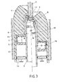
- the movable contact piece 3 is hollow and forms with the contact piece 2 in the switched-on state (left part of FIG. 3) a contact piece overlap with a contact surface 17.
- the contact piece 3 there is an offset downstream of the contact surface 17 in the axial direction Constriction 18 with an opening 19, the cross section of which is smaller than the cross section of the opening of the switching element 3, which is enclosed by the contact surface 17 supports and causes a pressure increase in the heating volume 5.
- the cross section of the opening 19 is preferably dimensioned such that the quenching gas exits from the volume 20 somewhat faster into the downstream part of the switching element 3 when the current passes zero the extinguishing gas from the heating volume 5 when the switching path is open.
Landscapes
- Circuit Breakers (AREA)
Abstract
Description
- Bei der Erfindung wird ausgegangen von einem Druckgasschalter nach dem gemeinsamen Oberbegriff der Patentansprüche 1 und 3.
- Mit diesem Oberbegriff nimmt die Erfindung auf einen Stand der Technik von Druckgasschaltern Bezug, wie er etwa in Fig. 1 der US-PS 4,139,752 beschrieben ist. Beim bekannten Schalter wird das vom Schaltlichtbogen erhitzte Löschgas in einem die Schaltstücke koaxial umgebenden, toroidal ausgebildeten Heizvolumen gespeichert und bebläst den Schaltlichtbogen radial, wenn die Heizwirkung des Schaltlichtbogens bei Annäherung des abzuschaltenden Stromes an einen Nulldurchgang nachlässt. Um hierbei eine möglichst wirkungsvolle Beblasung des Schaltlichtbogens zu ermöglichen, ist im Ringkanal eine Kühlvorrichtung vorgesehen. Durch diese Kühlvorrichtung wird die Temperatur des zur Beblasung des Schaltlichtbogens verwendeten Löschgases beim Durchströmen des Ringkanals herabgesetzt. Eine Kühlvorrichtung ist jedoch verhältnismässig aufwendig und erschwert sowohl die Strömung des Löschgases während der Hochstromphase in das Heizvolumen hinein als auch die Strömung des Löschgases bei Annäherung des abzuschaltenden Stromes an einen Nulldurchgang aus dem Heizvolumen heraus.
- Die Erfindung, wie sie in den Ansprüchen gekennzeichnet ist, löst die Aufgabe, einen Druckgasschalter der gattungsgemässen Art anzugeben, bei dem das zur Beblasung des Schaltlichtbogens vorgesehene Löschgas auch ohne Verwendung einer Kühlvorrichtung bei Gastemperaturen zur Verfügung steht, welche ganz erheblich unter der Temperatur des aufgeheizten Löschgases liegen.
- Die Aufgabe wird in Verbindung mit den Merkmalen des Oberbegriffs gemäss den kennzeichnenden Teilen der Ansprüche 1 und 3 gelöst. Der erfindungsgemässe Druckgasschalter zeichnet sich bei einfachem Aufbau durch ein hohes Löschvermögen aus. Dies ist dadurch bedingt, dass das beim Schaltvorgang erhitzte Löschgas im Heizvolumen eine Zirkulationsströmung erzeugt, durch welche das erhitzte Löschgas und im Heizvolumen befindliches kühles Löschgas sehr rasch vermischt werden.
- Vorteilhafte Weiterbildungen der Erfindung sind in den Unteransprüchen angegeben.
- Die Erfindung wird nachfolgend anhand der Zeichnung näher erläutert.
- Hierbei zeigt:
- Fig. 1 eine Aufsicht auf eine erste Ausführungsform eines längs seiner Schaltstückachse geschnittenen, erfindungsgemäss ausgebildeten Druckgasschalters,
- Fig. 2 eine Aufsicht auf eine zweite Ausführungsform eines längs seiner Schaltstückachse geschnittenen, erfindungsgemäss ausgebildeten Druckgasschalters, und
- Fig. 3 eine Aufsicht auf eine dritte Ausführungsform eines längs seiner Schaltstückachse geschnittenen, erfindungsgemäss ausgebildeten Druckgasschalters.
- In allen Figuren sind gleiche Teile mit gleichen Bezugszeichen versehen und sind die Druckgasschalter im linken Teil jeweils in der Einschaltstellung, im rechten Teil hingegen jeweils während des Ausschaltens dargestellt.
- In den Figuren ist ein mit einem Löschgas, wie etwa Schwefelhexafluorid von einigen bar Druck, gefülltes Gehäuse mit 1 bezeichnet. In diesem Gehäuse befinden sich ein feststehendes Schaltstück 2, ein bewegliches Schaltstück 3 und ein Isolierstoffkörper 4. Im Isolierstoffkörper 4 ist ein die Schaltstücke 2 und 3 toroidförmig umgebendes Heizvolumen 5 ausgespart, in welches ein Ringkanal 6 einmündet. Der Ringkanal 6 verbindet das Heizvolumen 5 mit einer beim Ausschalten zwischen den sich trennenden Schaltstücken 2 und 3 gebildeten und einen Schaltlichtbogen 7 aufnehmenden Lichtbogenlöschzone 8. Das Heizvolumen 5 weist eine axiale Erstreckung L und eine radiale Tiefe D auf und wird von zwei koaxial und zwei radial erstreckten Wänden begrenzt. Der Ringkanal 6 weist eine verglichen mit der axialen Längserstreckung L und radialen Tiefe D des Heizvolumens 5 geringe Breite B auf. Seine Abströmfläche ist grösser oder höchstens gleich der Summe der Abströmflächen einer im Isolierstoffkörper 4 vorgesehenen und vom beweglichen Schaltstück 3 im Einschaltzustand verschlossenen sowie einer im feststehenden Schaltstück 2 vorgesehenen düsenförmigen Oeffnung.
- Das Heizvolumen 5 ist vorzugsweise so bemessen, dass dessen axiale Längserstreckung und radiale Tiefe gemessen von der Einmündung des Ringkanals 6 in das Heizvolumen 5 ungefähr gleich gross sind.
- Beim Druckgasschalter gemäss Fig. 1 verläuft der Ringkanal 6 nahezu ausschliesslich in radialer Richtung durch die innere der beiden koaxial angeordneten Begrenzungswände des Heizvolumens 5 und mündet ungefähr gleich weit von den beiden radial erstreckten Begrenzungswänden des Heizvolumens 5 entfernt. Die Abstände L1 zwischen Einmündung des Ringkanals 6 und der oberen und unteren radial erstreckten Begrenzungswand des Heizvolumens 5 entsprechen in etwa der radialen Tiefe D des Heizvolumens 5.
- Beim Ausschalten (rechter Teil der Fig. 1) wird das als Vollzylinder ausgebildete Schaltstück 3 nach unten bewegt. Sobald dieses Schaltstück ausser Eingriff mit dem als Düsenrohr ausgebildeten Schaltstück 2 ist, bildet sich zwischen den Schaltstücken 2 und 3 der Schaltlichtbogen 7 aus. Der Schaltlichtbogen heizt in der Hochstromphase das in der Lichtbogenlöschzone 8 befindliche Löschgas stark auf, wodurch dessen Druck ansteigt. Das erhitzte Löschgas hohen Drucks strömt überwiegend durch den Ringkanal 6 in das Heizvolumen 5. Hierbei wird im Heizvolumen 5 eine durch Pfeile dargestellte Zirkulationsströmung erzeugt, welche sich zunächst überwiegend in radialer Richtung ausbildet, um sich dann nach Teilung an der äusseren koaxial ausgebildeten Begrenzungswand in den oberen und unteren Teil des Heizvolumens zu bewegen.
- Mischungsversuche haben ergeben, dass bei einem Heizvolumen 5, dessen axiale Längserstreckung L1 und radiale Tiefe D - jeweils gerechnet von der Einmündung des Ringkanals 6 in das Heizvolumen 5 - ungefähr gleich gross sind, und bei dem sich infolge einer erheblich unter der axialen Längserstreckung und der radialen Tiefe des Heizvolumens 5 liegenden Breite B des Ringkanals 6 eine kräftige Zirkulationsströmung ausbilden kann, innerhalb einer Halbwelle eines zu unterbrechenden Wechselstroms von 50 Hz aufgeheiztes und kühles Löschgas nahezu vollkommen durchmischt werden.
- Nach der Hochstromphase strömt das im Heizvolumen 5 befindliche durchmischte Löschgas über den Ringkanal 6 zurück in die Lichtbogenlöschzone 8, wo es den Schaltlichtbogen 7 bebläst, und danach über das als Düsenrohr ausgebildete Schaltstück 2 und eine im Isolierstoffkörper 4 vorgesehene und vom beweglichen Schaltstück 3 freigegebene Oeffnung in einen Expansionsraum gelangt.
- Beim Druckgasschalter gemäss Fig. 2 mündet der Ringkanal 6 tangential zur inneren der beiden koaxial erstreckten Begrenzungswände des Heizvolumens 5. Hierbei wird in der Hochstromphase ein in das Heizvolumen 5 eintretender Strahl aufgeheizten Löschgases in axialer Richtung längs der Begrenzungswand geführt (rechter Teil von Fig. 2), wobei eine die Durchmischung von aufgeheiztem und frischem Löschgas fördernde Zirkulationsströmung erzeugt wird.
- Darüber hinaus weist der Ringkanal 6 des Druckgasschalters gemäss Fig. 2 ein längs der inneren der koaxialen Begrenzungswände des Heizvolumens 5 erstrecktes Mündungsteil 9 sowie eine Engstelle 10 auf. Durch dies Massnahmen wird die Strahlwirkung des einströmenden aufgeheizten Löschgases und damit die Durchmischung von aufgeheiztem und kühlem Löschgas zusätzlich verstärkt.
- Eine weitere Verbesserung der Durchmischung wird ferner dadurch erreicht, dass das Heizvolumen 5 des Druckgasschalters gemäss Fig. 2 über einen Verbindungskanal 11 mit einem weiteren Volumen 12 kommuniziert. Der Verbindungskanal 11 endet in der Nähe der Mündung des Ringkanals 6 und ist parallel zum Ringkanal 6 angeordnet. Der Strömungsquerschnitt des Verbindungskanals 11 und die Grösse des Volumens 12 sind so gewählt, dass bei Druckanstieg im Volumen 5 der Druck im Volumen 12 relativ zum Druck im Volumen 5 um einen wesentlichen Betrag nachhinkt. Hierdurch wird erreicht, dass bei Annäherung an den Stromnulldurchgang aus dem Volumen 12 ein Strahl vergleichsweise frischen Löschgases austritt, welches dem aus dem Heizvolumen 5 abfliessenden vorgemischten Löschgas zusätzlich beigemischt wird. Für die Einmündung des Verbindungskanals 11 ins Volumen.12 und die Form des Volumens 12 werden vorzugsweise dieselben Auswahlkriterien angewandt wie für das Heizvolumen 5, um so eine möglichst gute Durchmischung von aufgeheiztem und frischem Löschgas im Volumen 12 zu erzielen.
- Beim Druckgasschalter gemäss Fig. 3 ist zusätzlich eine Vorrichtung zum Komprimieren von Löschgas vorgesehen. Diese Vorrichtung weist einen mit dem beweglichen Schaltstück 3 verbundenen Zylinder 13 sowie einen feststehenden und im Zylinder 13 in dichtender Weise axial verschiebbaren Kolben 14 auf. Beim Ausschalten wird das im Zylinder 13 oberhalb des Kolbens 14 befindliche Löschgas komprimiert und über einen Zuführkanal 15 in das Heizvolumen 5 geführt. Der Kanal 15 mündet tangential zu einer radial erstreckten Begrenzungsfläche des Heizvolumens 5. Durch diese Ausgestaltung des Druckgasschalters wird erreicht, dass während der Hochstromphase (rechter Teil von Fig. 3) die Zirkulationsströmung im Heizvolumen die Vermischung von aufgeheiztem Löschgas aus der Lichtbogenlöschzone 8 und von frischem Löschgas aus dem Heizvolumen 5 sowie aus der Kompressionsvorrichtung unterstützt.
- Um beim Schalten hoher Kurzschlussströme das Eintreten aufgeheizten Löschgases in die Kompressionsvorrichtung zu verhindern, ist im Kanal 13 noch ein Rückschlagventil 16 vorgesehen.
- Anstelle auf einer radial erstreckten Begrenzungswand des Heizvolumens 5 kann der Kanal 15 auch auf einer axial erstreckten Begrenzungswand des Heizvolumens einmünden. Wichtig ist bei der Führung des Kanals 15 vor allem, dass das bei einem Schaltvorgang aus dem Kanal 15 ausströmende Löschgas denselben Richtungssinn aufweist wie das tangential zu einer weiteren Begrenzungswand des Heizvolumens 5 einströmende und im Heizvolumen 5 zirkulierende Löschgas aus dem Ringkanal 6.
- Beim Druckgasschalter gemäss Fig. 3 ist das bewegliche Schaltstück 3 hohl ausgebildet und bildet mit dem Schaltstück 2 im Einschaltzustand (linker Teil von Fig. 3) eine Schaltstücküberlappung mit einer Berührungsfläche 17. Im Schaltstück 3 befindet sich stromabwärts der Berührungsfläche 17 in axialer Richtung versetzt eine Engstelle 18 mit einer Oeffnung 19, deren Querschnitt kleiner ist als der Querschnitt der von der Berührungsfläche 17 umschlossenen Oeffnung des Schaltstückes 3. Die Engstelle 18 schliesst ein vom stromaufwärts gelegenen Teil des Schaltstückes 3 begrenztes Volumen 20 ab, welches beim Ausschalten die Heizleistung des Schaltlichtbogens 7 unterstützt und eine Druckerhöhung im Heizvolumen 5 bewirkt. Damit beim Stromnulldurchgang keine Rückströmung von überhitztem Löschgas aus dem Volumen 20 in die Lichtbogenlöschzone 8 stattfinden kann, ist der Querschnitt der Oeffnung 19 vorzugsweise so bemessen, dass beim Stromnulldurchgang das Löschgas aus dem Volumen 20 etwas rascher in den stromabwärts gelegenen Teil des Schaltstückes 3 austritt als das Löschgas aus dem Heizvolumen 5 bei geöffneter Schaltstrecke.
Claims (11)
Applications Claiming Priority (2)
| Application Number | Priority Date | Filing Date | Title |
|---|---|---|---|
| CH277284 | 1984-06-07 | ||
| CH2772/84 | 1984-06-07 |
Publications (3)
| Publication Number | Publication Date |
|---|---|
| EP0163943A2 true EP0163943A2 (de) | 1985-12-11 |
| EP0163943A3 EP0163943A3 (en) | 1986-12-30 |
| EP0163943B1 EP0163943B1 (de) | 1989-08-09 |
Family
ID=4241262
Family Applications (1)
| Application Number | Title | Priority Date | Filing Date |
|---|---|---|---|
| EP85105322A Expired EP0163943B1 (de) | 1984-06-07 | 1985-05-02 | Druckgasschalter |
Country Status (6)
| Country | Link |
|---|---|
| US (1) | US4652709A (de) |
| EP (1) | EP0163943B1 (de) |
| JP (1) | JPH07105184B2 (de) |
| DE (2) | DE3425633A1 (de) |
| ES (2) | ES296664Y (de) |
| IN (1) | IN164798B (de) |
Cited By (3)
| Publication number | Priority date | Publication date | Assignee | Title |
|---|---|---|---|---|
| EP0290950A1 (de) * | 1987-05-13 | 1988-11-17 | BBC Brown Boveri AG | Druckgasschalter |
| EP0817228A3 (de) * | 1996-07-05 | 1998-12-23 | Asea Brown Boveri AG | Leistungsschalter |
| EP0836209A3 (de) * | 1996-10-09 | 1999-04-07 | Asea Brown Boveri AG | Leistungsschalter |
Families Citing this family (5)
| Publication number | Priority date | Publication date | Assignee | Title |
|---|---|---|---|---|
| JPH02239291A (ja) * | 1989-03-13 | 1990-09-21 | Nippon Telegr & Teleph Corp <Ntt> | 文節音声認識装置 |
| DE4140776A1 (de) * | 1991-12-06 | 1993-06-09 | Siemens Ag, 8000 Muenchen, De | Metallgekapselte gasisolierte schaltanlage mit einem kabelanschlussgehaeuse |
| DE19629475A1 (de) * | 1996-07-10 | 1998-01-15 | Siemens Ag | Druckgasleistungsschalter |
| DE502005006389D1 (de) | 2005-11-01 | 2009-02-12 | Abb Technology Ltd | Schaltkammer eines Hochspannungsschalters mit einem Heizvolumen zur Aufnahme von Druckgas |
| FR3030106B1 (fr) * | 2014-12-11 | 2017-01-13 | Alstom Technology Ltd | Dispositif de coupure electrique haute tension a autosoufflage optimise |
Family Cites Families (14)
| Publication number | Priority date | Publication date | Assignee | Title |
|---|---|---|---|---|
| DE647726C (de) * | 1932-11-18 | 1937-07-10 | Siemens Schuckertwerke Akt Ges | Einrichtung fuer die Loeschung von Wechselstromlichtboegen |
| DE671502C (de) * | 1935-05-12 | 1939-02-08 | Studiengesellschaft Fuer Hochl | Druckgasschalter mit druckabhaengiger Kammerentlastung |
| DE1127442B (de) * | 1959-06-10 | 1962-04-12 | Siemens Ag | Elektrischer Fluessigkeitsschalter |
| DE1127443B (de) * | 1959-12-12 | 1962-04-12 | Sachsenwerk Licht & Kraft Ag | Querstroemungsloeschkammer fuer elektrische Fluessigkeitsleistungsschalter |
| SE336160B (de) * | 1967-12-29 | 1971-06-28 | Asea Ab | |
| JPS524067A (en) * | 1975-05-30 | 1977-01-12 | Mitsubishi Electric Corp | Gas breaker |
| FR2373141A1 (fr) * | 1976-12-06 | 1978-06-30 | Cem Comp Electro Mec | Appareil electrique de coupure a haute tension, notamment un disjoncteur a autosoufflage de l'arc de coupure par un gaz |
| CH632609A5 (de) * | 1977-03-24 | 1982-10-15 | Mitsubishi Electric Corp | Stromunterbrecher mit lichtbogenloeschendem gas. |
| DE2811508C2 (de) * | 1977-03-24 | 1983-06-16 | Mitsubishi Denki K.K., Tokyo | Elektrischer Druckgasschalter |
| JPS5438569A (en) * | 1977-08-31 | 1979-03-23 | Mitsubishi Electric Corp | Switch |
| JPS55128221A (en) * | 1979-03-26 | 1980-10-03 | Mitsubishi Electric Corp | Switch |
| CH649416A5 (de) * | 1980-01-25 | 1985-05-15 | Sprecher & Schuh Ag | Druckgasschalter. |
| FR2520928A1 (fr) * | 1982-02-04 | 1983-08-05 | Alsthom Atlantique | Disjoncteur a auto-soufflage pneumatique |
| JPS60167225A (ja) * | 1984-02-10 | 1985-08-30 | 株式会社日立製作所 | ガス遮断器 |
-
1984
- 1984-07-12 DE DE19843425633 patent/DE3425633A1/de not_active Withdrawn
-
1985
- 1985-05-02 DE DE8585105322T patent/DE3572250D1/de not_active Expired
- 1985-05-02 EP EP85105322A patent/EP0163943B1/de not_active Expired
- 1985-05-21 IN IN374/MAS/85A patent/IN164798B/en unknown
- 1985-05-31 US US06/739,622 patent/US4652709A/en not_active Expired - Lifetime
- 1985-06-07 ES ES1985296664U patent/ES296664Y/es not_active Expired
- 1985-06-07 JP JP60122862A patent/JPH07105184B2/ja not_active Expired - Lifetime
-
1986
- 1986-09-01 ES ES1986297077U patent/ES297077Y/es not_active Expired
Cited By (5)
| Publication number | Priority date | Publication date | Assignee | Title |
|---|---|---|---|---|
| EP0290950A1 (de) * | 1987-05-13 | 1988-11-17 | BBC Brown Boveri AG | Druckgasschalter |
| US4798924A (en) * | 1987-05-13 | 1989-01-17 | Bbc Brown Boveri & Co., Ltd. | Compressed-gas breaker |
| EP0817228A3 (de) * | 1996-07-05 | 1998-12-23 | Asea Brown Boveri AG | Leistungsschalter |
| EP0836209A3 (de) * | 1996-10-09 | 1999-04-07 | Asea Brown Boveri AG | Leistungsschalter |
| US5905243A (en) * | 1996-10-09 | 1999-05-18 | Asea Brown Boveri Ag | Power breaker |
Also Published As
| Publication number | Publication date |
|---|---|
| DE3572250D1 (en) | 1989-09-14 |
| ES297077Y (es) | 1989-07-16 |
| EP0163943A3 (en) | 1986-12-30 |
| JPS614119A (ja) | 1986-01-10 |
| JPH07105184B2 (ja) | 1995-11-13 |
| US4652709A (en) | 1987-03-24 |
| ES296664U (es) | 1988-01-01 |
| ES296664Y (es) | 1989-08-16 |
| IN164798B (de) | 1989-06-03 |
| EP0163943B1 (de) | 1989-08-09 |
| DE3425633A1 (de) | 1985-12-12 |
| ES297077U (es) | 1989-01-01 |
Similar Documents
| Publication | Publication Date | Title |
|---|---|---|
| DE3440212A1 (de) | Druckgasschalter | |
| EP0067460B1 (de) | Hochspannungsleistungsschalter | |
| EP0163943A2 (de) | Druckgasschalter | |
| DE2438017C3 (de) | Druckgasschalter | |
| EP2316122B1 (de) | Hochspannungs-leistungsschalter mit einer schaltstrecke | |
| DE2030605B2 (de) | Elektrischer Druckgasschalter mit einer Blaseinrichtung zur Erzeugung einer Löschgasströmung | |
| DE3915700C3 (de) | Druckgasschalter mit Verdampfungskühlung | |
| DE3341930C2 (de) | Druckgasschalter | |
| DE2759267B2 (de) | Druckgasschalter | |
| EP0160853B2 (de) | Druckgasschalter | |
| EP0290950B1 (de) | Druckgasschalter | |
| EP0081253A1 (de) | Druckgasschalter | |
| DE69023471T2 (de) | Gaslastschalter. | |
| WO2009124582A1 (de) | Gasisolierter hochspannungsschalter | |
| EP0817228B1 (de) | Leistungsschalter | |
| DE19850395A1 (de) | Leistungsschalter | |
| EP0175209B1 (de) | Druckgasschalter | |
| EP1248500A2 (de) | Schweissbrenner | |
| DE3535194A1 (de) | Druckgasschalter | |
| EP0039523A1 (de) | Hochspannungsleistungsschalter | |
| EP1780741B2 (de) | Schaltkammer eines Hochspannungsschalters mit einem Heizvolumen zur Aufnahme von Druckgas | |
| DE2759265B2 (de) | Druckgasschalter | |
| EP0100749A1 (de) | Schaltkammer für einen Druckgas-Leistungsschalter | |
| DE2910495A1 (de) | Schaltervorrichtung mit selbsttaetiger lichtbogenloeschung | |
| WO2016124175A1 (de) | Leistungsschalter |
Legal Events
| Date | Code | Title | Description |
|---|---|---|---|
| PUAI | Public reference made under article 153(3) epc to a published international application that has entered the european phase |
Free format text: ORIGINAL CODE: 0009012 |
|
| AK | Designated contracting states |
Designated state(s): CH DE FR GB IT LI |
|
| PUAL | Search report despatched |
Free format text: ORIGINAL CODE: 0009013 |
|
| AK | Designated contracting states |
Kind code of ref document: A3 Designated state(s): CH DE FR GB IT LI |
|
| 17P | Request for examination filed |
Effective date: 19861222 |
|
| RAP1 | Party data changed (applicant data changed or rights of an application transferred) |
Owner name: BBC BROWN BOVERI AG |
|
| 17Q | First examination report despatched |
Effective date: 19880802 |
|
| GRAA | (expected) grant |
Free format text: ORIGINAL CODE: 0009210 |
|
| AK | Designated contracting states |
Kind code of ref document: B1 Designated state(s): CH DE FR GB IT LI |
|
| REF | Corresponds to: |
Ref document number: 3572250 Country of ref document: DE Date of ref document: 19890914 |
|
| ET | Fr: translation filed | ||
| ITF | It: translation for a ep patent filed | ||
| GBT | Gb: translation of ep patent filed (gb section 77(6)(a)/1977) | ||
| PLBE | No opposition filed within time limit |
Free format text: ORIGINAL CODE: 0009261 |
|
| STAA | Information on the status of an ep patent application or granted ep patent |
Free format text: STATUS: NO OPPOSITION FILED WITHIN TIME LIMIT |
|
| 26N | No opposition filed | ||
| ITTA | It: last paid annual fee | ||
| PGFP | Annual fee paid to national office [announced via postgrant information from national office to epo] |
Ref country code: GB Payment date: 19980414 Year of fee payment: 14 |
|
| PGFP | Annual fee paid to national office [announced via postgrant information from national office to epo] |
Ref country code: FR Payment date: 19980417 Year of fee payment: 14 |
|
| PGFP | Annual fee paid to national office [announced via postgrant information from national office to epo] |
Ref country code: DE Payment date: 19980420 Year of fee payment: 14 |
|
| PGFP | Annual fee paid to national office [announced via postgrant information from national office to epo] |
Ref country code: CH Payment date: 19980430 Year of fee payment: 14 |
|
| PG25 | Lapsed in a contracting state [announced via postgrant information from national office to epo] |
Ref country code: GB Free format text: LAPSE BECAUSE OF NON-PAYMENT OF DUE FEES Effective date: 19990502 |
|
| PG25 | Lapsed in a contracting state [announced via postgrant information from national office to epo] |
Ref country code: LI Free format text: LAPSE BECAUSE OF NON-PAYMENT OF DUE FEES Effective date: 19990531 Ref country code: CH Free format text: LAPSE BECAUSE OF NON-PAYMENT OF DUE FEES Effective date: 19990531 |
|
| GBPC | Gb: european patent ceased through non-payment of renewal fee |
Effective date: 19990502 |
|
| REG | Reference to a national code |
Ref country code: CH Ref legal event code: PL |
|
| PG25 | Lapsed in a contracting state [announced via postgrant information from national office to epo] |
Ref country code: FR Free format text: LAPSE BECAUSE OF NON-PAYMENT OF DUE FEES Effective date: 20000131 |
|
| PG25 | Lapsed in a contracting state [announced via postgrant information from national office to epo] |
Ref country code: DE Free format text: LAPSE BECAUSE OF NON-PAYMENT OF DUE FEES Effective date: 20000301 |
|
| REG | Reference to a national code |
Ref country code: FR Ref legal event code: ST |