EP0164419A1 - Dispositif de serrage de moule - Google Patents
Dispositif de serrage de moule Download PDFInfo
- Publication number
- EP0164419A1 EP0164419A1 EP84904175A EP84904175A EP0164419A1 EP 0164419 A1 EP0164419 A1 EP 0164419A1 EP 84904175 A EP84904175 A EP 84904175A EP 84904175 A EP84904175 A EP 84904175A EP 0164419 A1 EP0164419 A1 EP 0164419A1
- Authority
- EP
- European Patent Office
- Prior art keywords
- servo motor
- toggle
- toggle mechanism
- links
- molds
- Prior art date
- Legal status (The legal status is an assumption and is not a legal conclusion. Google has not performed a legal analysis and makes no representation as to the accuracy of the status listed.)
- Granted
Links
Images

Classifications
-
- B—PERFORMING OPERATIONS; TRANSPORTING
- B29—WORKING OF PLASTICS; WORKING OF SUBSTANCES IN A PLASTIC STATE IN GENERAL
- B29C—SHAPING OR JOINING OF PLASTICS; SHAPING OF MATERIAL IN A PLASTIC STATE, NOT OTHERWISE PROVIDED FOR; AFTER-TREATMENT OF THE SHAPED PRODUCTS, e.g. REPAIRING
- B29C45/00—Injection moulding, i.e. forcing the required volume of moulding material through a nozzle into a closed mould; Apparatus therefor
- B29C45/17—Component parts, details or accessories; Auxiliary operations
- B29C45/64—Mould opening, closing or clamping devices
- B29C45/66—Mould opening, closing or clamping devices mechanical
- B29C45/661—Mould opening, closing or clamping devices mechanical using a toggle mechanism for mould clamping
-
- B—PERFORMING OPERATIONS; TRANSPORTING
- B29—WORKING OF PLASTICS; WORKING OF SUBSTANCES IN A PLASTIC STATE IN GENERAL
- B29C—SHAPING OR JOINING OF PLASTICS; SHAPING OF MATERIAL IN A PLASTIC STATE, NOT OTHERWISE PROVIDED FOR; AFTER-TREATMENT OF THE SHAPED PRODUCTS, e.g. REPAIRING
- B29C45/00—Injection moulding, i.e. forcing the required volume of moulding material through a nozzle into a closed mould; Apparatus therefor
- B29C45/17—Component parts, details or accessories; Auxiliary operations
- B29C45/64—Mould opening, closing or clamping devices
- B29C45/68—Mould opening, closing or clamping devices hydro-mechanical
- B29C45/681—Mould opening, closing or clamping devices hydro-mechanical using a toggle mechanism as mould clamping device
Definitions
- the present invention relates to a toggle type lock in an injection molding apparatus.
- a conventional toggle type lock in an injection molding apparatus is driven by a hydraulic mechanism. For this reason, a hydraulic pump, valves or the like are required to complicate the construction of the conventional lock drive mechanism.
- the locking operation must be controlled by a hydraulic pressure. As a result, locking speed control is complex and cannot be easily performed.
- a lock in an injection molding apparatus for causing a toggle mechanism to perform locking comprises a servo motor and a transmission mechanism having a screw and a nut mechanism for converting the rotational force of the servo motor to a linear force, the toggle mechanism being driven by an output from the transmission mechanism.
- the servo motor is used as a drive source of the toggle mechanism for performing locking, so that locking speed control can be easily performed to obtain a desired locking speed. Furthermore, since a toggle mechanism is employed, a compact servo motor can be used, thus resulting in a simple structure and easy maintenance.
- a position sensor mounted on the servo motor precisely controls the positions of the screw and the toggle mechanism, thereby simplifying locking force control.
- a hydraulic mechanism is not used, so that operation reliability is improved.
- a hydraulic pump is operated with power to generate a hydraulic pressure used to drive the drive mechanism.
- a large power loss occurs.
- electric power is used only to drive the servo motor, and the drive mechanism is directly driven by the output from the servo motor. As a result, an energy loss can be decreased.
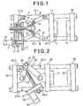
- Fig. 1 shows a first embodiment of the present invention
- Fig. 2 shows a second embodiment of the present invention
- Fig. 3 shows a third embodiment of the present invention.
- Fig. 1 shows a first embodiment of the present invention.
- Reference numeral 1 denotes a servo motor; 2 and 3, gears, respectively; 4, a nut fixed on the gear 3 l and 5, a screw engaged with the nut 4.
- the gears 2 and 3, the nut 4, the screw 5 and the like constitute a transmission mechanism for transmitting power from the servo motor 1 to a toggle mechanism 6.
- the toggle mechanism 6 is of double toggle type.
- One end of each of links 9 and 9' is pivotally supported by a crosshead 10 mounted at a distal end of the screw 5.
- the other end of each of the links 9 and 9' is pivotally supported by a corresponding one of links 7 and 7'.
- Links 8 and 8' are pivotally supported by the links 7 and 7', respectively.
- the links 7 and 7' are pivotally supported by a fixed back pressure plate 12.
- the links 8 and 8' are pivotally supported by a movable base 11.
- the links 7 and 7', 8 and 8' and 9 and 9' and the crosshead 10 constitute the toggle mechanism 6.
- Reference numerals 14 and 15 denote molds, respectively.
- the molds 14 and 15 are fixed on the movable base 11 and a fixed base 16.
- the fixed base 16 and the fixed back pressure plate 14 are connected by four tie bars 17-1 to 17-4.
- the movable base 11 can be moved by the toggle mechanism 6 between the tie bars 17-1 to 17-4 along the right-and-left direction of Fig. 1.
- Reference numeral 13 denotes a coupling device for transmitting the output from the servo motor 1 to the gear 2.
- Reference numeral 19 denotes a position sensor mounted on the servo motor 1.
- the movable base 11 and the mold 14 fixed on the movable base 11 are shifted to the right in Fig. 1.
- the molds 14 and 15 are closed immediately before the links 7 and 8 and the links 7' and 8 1 become straight.
- the servo motor 1 is stopped.
- the tie bars 17-1 to 17-4 are kept taut to a degree that the links 7 and 8 and the links 7' and 8' are kept completely straight.
- the molds 14 and 15 are clamped by an elastic restoration force generated by extension of the tie bars 17-1 to 17-4.
- the servo motor 1 is rotated in the reverse direction to shift the screw 5 to the left in Fig. 1, thereby obtaining the state of Fig. 1.
- Figs. 2 and 3 show other embodiments using single toggle mechanisms, respectively.
- Reference numeral 20 denotes a servo-motor; 21, a gear box; 22, a screw; 23, a toggle mechanism; 24 and 25, links in the toggle mechanism 23; and 26, a nut pivotally mounted on the link 25.
- the nut 26 is meshed with the screw 22.
- Reference numeral 27 denotes a joint between the links 24 and 26; 28, a fixed back pressure plate; 29, a movable base; 30, a fixed base; 31 and 32, molds, respectively; 33-1 to 33-4, tie bars, respectively; and 34, a position sensor.
- Fig. 3 is substantially the same as that of Fig. 2, except that the nut 26 is pushed while the nut 26 is pulled toward the servo motor 20 upon rotation of the screw 22 in the second embodiment.
Landscapes
- Engineering & Computer Science (AREA)
- Manufacturing & Machinery (AREA)
- Mechanical Engineering (AREA)
- Moulds For Moulding Plastics Or The Like (AREA)
- Press Drives And Press Lines (AREA)
Abstract
Applications Claiming Priority (2)
| Application Number | Priority Date | Filing Date | Title |
|---|---|---|---|
| JP219515/83 | 1983-11-24 | ||
| JP21951583A JPS60112417A (ja) | 1983-11-24 | 1983-11-24 | 型締装置 |
Publications (3)
| Publication Number | Publication Date |
|---|---|
| EP0164419A1 true EP0164419A1 (fr) | 1985-12-18 |
| EP0164419A4 EP0164419A4 (fr) | 1986-11-26 |
| EP0164419B1 EP0164419B1 (fr) | 1989-03-08 |
Family
ID=16736670
Family Applications (1)
| Application Number | Title | Priority Date | Filing Date |
|---|---|---|---|
| EP19840904175 Expired EP0164419B1 (fr) | 1983-11-24 | 1984-11-20 | Dispositif de serrage de moule |
Country Status (4)
| Country | Link |
|---|---|
| EP (1) | EP0164419B1 (fr) |
| JP (1) | JPS60112417A (fr) |
| DE (1) | DE3476978D1 (fr) |
| WO (1) | WO1985002363A1 (fr) |
Cited By (14)
| Publication number | Priority date | Publication date | Assignee | Title |
|---|---|---|---|---|
| EP0201610A4 (fr) * | 1984-11-24 | 1988-03-22 | Fanuc Ltd | Procede de fermeture du moule dans une machine de moulage par injection. |
| GB2236503A (en) * | 1989-08-23 | 1991-04-10 | Gerald Dennis Day | Mould clamps |
| EP0456335A1 (fr) * | 1990-05-07 | 1991-11-13 | MANNESMANN Aktiengesellschaft | Dispositif pour fermer les moules d'une machine à mouler par injection |
| EP0500679A4 (fr) * | 1989-11-06 | 1992-07-02 | Cincinnati Milacron Inc | Systeme de serrage de moule. |
| WO1994004337A1 (fr) | 1992-08-25 | 1994-03-03 | Battenfeld Kunststoffmaschinen Ges.M.B.H. | Unite de fermeture d'outils de formage pour presses d'injection |
| EP0626245A3 (fr) * | 1993-04-24 | 1995-04-05 | Karl Hehl | Unité de fermeture de moule pour une machine à mouler par injection les matières plastiques. |
| DE4409822A1 (de) * | 1994-02-19 | 1995-08-24 | Procontrol Ag | Antrieb für die linear bewegbaren Achsen einer Spritzgießmaschine |
| EP0965429A1 (fr) * | 1998-06-18 | 1999-12-22 | Sumitomo Heavy Industries, Ltd. | Dispositif de serrage de moule entraíné par moteur et procédé de serrage de moule |
| WO2001047685A1 (fr) * | 1999-12-27 | 2001-07-05 | Mannesmann Plastics Machinery Ag | Dispositif de fermeture pour machine de moulage par injection pour matieres plastiques |
| DE4328844C2 (de) * | 1993-08-27 | 2002-06-13 | Battenfeld Kunststoffmasch | Spritzgießmaschine, insbesondere Kunststoffspritzgießmaschine |
| US11931939B1 (en) | 2022-10-25 | 2024-03-19 | Haw Chan Tan | Toggle mechanism for closing of a mold in a molding machine |
| DE102023111741A1 (de) | 2023-05-05 | 2024-11-07 | Arburg Gmbh + Co Kg | Formschließeinheit |
| DE102023111742A1 (de) | 2023-05-05 | 2024-11-07 | Arburg Gmbh + Co Kg | Formschließeinheit |
| DE102023111740A1 (de) | 2023-05-05 | 2024-11-07 | Arburg Gmbh + Co Kg | Formschließeinheit |
Families Citing this family (21)
| Publication number | Priority date | Publication date | Assignee | Title |
|---|---|---|---|---|
| JPS623917A (ja) * | 1985-06-29 | 1987-01-09 | Toshiba Mach Co Ltd | 型締装置 |
| JPS6271620A (ja) * | 1985-09-26 | 1987-04-02 | Fanuc Ltd | 射出成形機における型締プラテン位置表示装置 |
| JPS62102620U (fr) * | 1985-12-18 | 1987-06-30 | ||
| JPS62161516A (ja) * | 1986-01-11 | 1987-07-17 | Fanuc Ltd | エジエクト開始方式 |
| JPS62207618A (ja) * | 1986-03-08 | 1987-09-12 | Fanuc Ltd | 射出成形機の金型保護装置 |
| JPS63116820A (ja) * | 1986-11-06 | 1988-05-21 | Japan Steel Works Ltd:The | 射出成形機の型締制御装置 |
| JPS6380118U (fr) * | 1986-11-14 | 1988-05-27 | ||
| DE3743037A1 (de) * | 1987-12-18 | 1989-06-29 | Buehler Ag Geb | Pelletpresse |
| JPH02133288U (fr) * | 1989-04-07 | 1990-11-06 | ||
| AT396903B (de) * | 1991-09-20 | 1993-12-27 | Engel Gmbh Maschbau | Spritzgiessmaschine |
| AT399842B (de) * | 1993-03-01 | 1995-07-25 | Engel Gmbh Maschbau | Spritzgiessmaschine |
| DE4313473C2 (de) * | 1993-03-20 | 1996-12-19 | Karl Hehl | Schließeinheit für eine Spritzgießmaschine |
| JP2927192B2 (ja) * | 1994-10-03 | 1999-07-28 | 村田機械株式会社 | パンチ駆動装置 |
| DE19702889C2 (de) * | 1996-01-26 | 2001-09-06 | Engel Gmbh Maschbau | Antriebseinrichtung für einen Schließmechanismus und/oder eine Einspritzeinheit einer Spritzgießmaschine |
| JP3240350B2 (ja) * | 1997-04-24 | 2001-12-17 | 日精樹脂工業株式会社 | 射出成形機のモータ制御装置 |
| KR100256493B1 (ko) * | 1997-12-01 | 2000-05-15 | 최녹일 | 성형프레스의 가압력 조절장치 |
| DE19923849C2 (de) * | 1999-05-25 | 2003-04-03 | Karl Hehl | Formschließeinheit für eine Spritzgießmaschine |
| JP3886730B2 (ja) * | 2001-01-29 | 2007-02-28 | 三菱重工プラスチックテクノロジー株式会社 | 電動式トグル型締装置及び電動式ハーフナット開閉装置 |
| JP5653859B2 (ja) * | 2011-07-26 | 2015-01-14 | 住友重機械工業株式会社 | 射出成形機 |
| ITUB20169997A1 (it) | 2016-01-14 | 2017-07-14 | Negri Bossi Spa | Gruppo di chiusura a ginocchiera per pressa ad iniezione |
| DE102024121787B3 (de) | 2024-07-31 | 2025-09-18 | Arburg Gmbh + Co Kg | Antrieb für eine Formschließeinheit einer Spritzgießmaschine sowie Formschließeinheit oder Spritzgießmaschine mit solchem Antrieb |
Family Cites Families (12)
| Publication number | Priority date | Publication date | Assignee | Title |
|---|---|---|---|---|
| GB288398A (en) * | 1927-02-03 | 1928-04-12 | William Hanson Boorne | An improved power press |
| DE518347C (de) * | 1929-07-21 | 1931-02-14 | Theodor Kraegeloh & Co | Kniehebelpresse |
| FR1183875A (fr) * | 1957-10-03 | 1959-07-15 | Const Mecaniques Sa Renens | Mécanisme de fermeture de presse par genouillère |
| AT246982B (de) * | 1963-03-25 | 1966-05-10 | Battenfeld Geb | Spritzgußmaschine zur Verarbeitung thermoplastischer Kunststoffe |
| CH491739A (de) * | 1968-05-09 | 1970-06-15 | Buehler Ag Geb | Verfahren zum Betrieb einer Presse, Vorrichtung zur Ausführung des Verfahrens und Anwendung des Verfahrens |
| JPS4874673U (fr) * | 1971-12-21 | 1973-09-17 | ||
| JPS5746316B2 (fr) * | 1973-08-09 | 1982-10-02 | ||
| JPS538484A (en) * | 1976-07-12 | 1978-01-25 | Yaskawa Electric Mfg Co Ltd | Controller for moving body |
| JPS5660591U (fr) * | 1979-10-15 | 1981-05-23 | ||
| JPS5914301B2 (ja) * | 1981-03-31 | 1984-04-04 | 本田技研工業株式会社 | 成形機の型開閉装置 |
| JPS5862030A (ja) * | 1981-10-08 | 1983-04-13 | Nissei Plastics Ind Co | 射出成形機 |
| JPS58107259A (ja) * | 1981-12-18 | 1983-06-25 | Toyo Kikai Kinzoku Kk | トグル式型締機構を有する成形機における低圧型締方法 |
-
1983
- 1983-11-24 JP JP21951583A patent/JPS60112417A/ja active Granted
-
1984
- 1984-11-20 EP EP19840904175 patent/EP0164419B1/fr not_active Expired
- 1984-11-20 WO PCT/JP1984/000555 patent/WO1985002363A1/fr not_active Ceased
- 1984-11-20 DE DE8484904175T patent/DE3476978D1/de not_active Expired
Cited By (19)
| Publication number | Priority date | Publication date | Assignee | Title |
|---|---|---|---|---|
| EP0201610A4 (fr) * | 1984-11-24 | 1988-03-22 | Fanuc Ltd | Procede de fermeture du moule dans une machine de moulage par injection. |
| GB2236503A (en) * | 1989-08-23 | 1991-04-10 | Gerald Dennis Day | Mould clamps |
| EP0500679A4 (fr) * | 1989-11-06 | 1992-07-02 | Cincinnati Milacron Inc | Systeme de serrage de moule. |
| EP0456335A1 (fr) * | 1990-05-07 | 1991-11-13 | MANNESMANN Aktiengesellschaft | Dispositif pour fermer les moules d'une machine à mouler par injection |
| US5178888A (en) * | 1990-05-07 | 1993-01-12 | Mannesmann Aktiengesellschaft | Device for closing molds of an injection molding machine |
| WO1994004337A1 (fr) | 1992-08-25 | 1994-03-03 | Battenfeld Kunststoffmaschinen Ges.M.B.H. | Unite de fermeture d'outils de formage pour presses d'injection |
| US5585126A (en) * | 1992-08-25 | 1996-12-17 | Battenfeld Kunststoffmaschinen Ges.M.B.H. | Closing unit for form tools of an injection molding machine |
| US5511963A (en) * | 1993-04-24 | 1996-04-30 | Hehl; Karl | Mold closing unit for use in an injection molding machine for processing synthetic materials |
| EP0626245A3 (fr) * | 1993-04-24 | 1995-04-05 | Karl Hehl | Unité de fermeture de moule pour une machine à mouler par injection les matières plastiques. |
| DE4328844C2 (de) * | 1993-08-27 | 2002-06-13 | Battenfeld Kunststoffmasch | Spritzgießmaschine, insbesondere Kunststoffspritzgießmaschine |
| DE4409822A1 (de) * | 1994-02-19 | 1995-08-24 | Procontrol Ag | Antrieb für die linear bewegbaren Achsen einer Spritzgießmaschine |
| EP0965429A1 (fr) * | 1998-06-18 | 1999-12-22 | Sumitomo Heavy Industries, Ltd. | Dispositif de serrage de moule entraíné par moteur et procédé de serrage de moule |
| WO2001047685A1 (fr) * | 1999-12-27 | 2001-07-05 | Mannesmann Plastics Machinery Ag | Dispositif de fermeture pour machine de moulage par injection pour matieres plastiques |
| US6682334B2 (en) | 1999-12-27 | 2004-01-27 | Mannesmann Plastics Machinery Gmbh | Closing unit for use in an injection molding machine for processing plastic material |
| US11931939B1 (en) | 2022-10-25 | 2024-03-19 | Haw Chan Tan | Toggle mechanism for closing of a mold in a molding machine |
| DE102023111741A1 (de) | 2023-05-05 | 2024-11-07 | Arburg Gmbh + Co Kg | Formschließeinheit |
| DE102023111742A1 (de) | 2023-05-05 | 2024-11-07 | Arburg Gmbh + Co Kg | Formschließeinheit |
| DE102023111740A1 (de) | 2023-05-05 | 2024-11-07 | Arburg Gmbh + Co Kg | Formschließeinheit |
| WO2024231235A1 (fr) | 2023-05-05 | 2024-11-14 | Arburg Gmbh + Co Kg | Unité de fermeture de moule et son procédé de fonctionnement |
Also Published As
| Publication number | Publication date |
|---|---|
| JPH0122135B2 (fr) | 1989-04-25 |
| WO1985002363A1 (fr) | 1985-06-06 |
| JPS60112417A (ja) | 1985-06-18 |
| EP0164419A4 (fr) | 1986-11-26 |
| EP0164419B1 (fr) | 1989-03-08 |
| DE3476978D1 (en) | 1989-04-13 |
Similar Documents
| Publication | Publication Date | Title |
|---|---|---|
| EP0164419B1 (fr) | Dispositif de serrage de moule | |
| US4642044A (en) | Lock | |
| US4781568A (en) | Mold clamping unit of injection molding machine | |
| CA1321049C (fr) | Dispositif articule de serrage de moule pour installation electrique de moulage par injection | |
| EP0275318B1 (fr) | Systeme de serrage de moule a action directe | |
| EP0451294B1 (fr) | Dispositif d'injection du type a manivelle | |
| EP0965429B1 (fr) | Procédé de serrage de moule | |
| US6554606B1 (en) | Mold clamping apparatus of injection molding machine | |
| JPS631516A (ja) | 射出成形機 | |
| JPH1128747A (ja) | 成形機の型締め装置 | |
| US6053724A (en) | Double toggle mechanism | |
| KR880002525B1 (ko) | 형체 장치 | |
| JP2002200658A (ja) | 射出成形機の型締め装置 | |
| JP4626870B2 (ja) | 射出成形機の駆動装置 | |
| GB2022499A (en) | Drive for an injection moulding machine | |
| JP2000110901A (ja) | 駆動装置及び射出成形機 | |
| CN222327917U (zh) | 一种带齿轮连杆增力机构的夹具 | |
| JPH0616932B2 (ja) | 成形機の型締め装置 | |
| JPH02121807A (ja) | 型締装置 | |
| JPH043894B2 (fr) | ||
| JP2515204B2 (ja) | 複合式型締装置における型締方法及び駆動装置 | |
| US20050248307A1 (en) | Method for controlling induction motor | |
| JPS6264520A (ja) | 電動式型締装置 | |
| JP2744333B2 (ja) | 電動モータを用いた型締装置 | |
| JPH07329135A (ja) | 成形装置の型締装置 |
Legal Events
| Date | Code | Title | Description |
|---|---|---|---|
| PUAI | Public reference made under article 153(3) epc to a published international application that has entered the european phase |
Free format text: ORIGINAL CODE: 0009012 |
|
| 17P | Request for examination filed |
Effective date: 19850813 |
|
| AK | Designated contracting states |
Designated state(s): CH DE LI |
|
| A4 | Supplementary search report drawn up and despatched |
Effective date: 19861126 |
|
| 17Q | First examination report despatched |
Effective date: 19871008 |
|
| GRAA | (expected) grant |
Free format text: ORIGINAL CODE: 0009210 |
|
| AK | Designated contracting states |
Kind code of ref document: B1 Designated state(s): CH DE LI |
|
| REF | Corresponds to: |
Ref document number: 3476978 Country of ref document: DE Date of ref document: 19890413 |
|
| PLBI | Opposition filed |
Free format text: ORIGINAL CODE: 0009260 |
|
| 26 | Opposition filed |
Opponent name: BATTENFELD GMBH Effective date: 19891208 |
|
| PLBN | Opposition rejected |
Free format text: ORIGINAL CODE: 0009273 |
|
| STAA | Information on the status of an ep patent application or granted ep patent |
Free format text: STATUS: OPPOSITION REJECTED |
|
| 27O | Opposition rejected |
Effective date: 19920630 |
|
| PGFP | Annual fee paid to national office [announced via postgrant information from national office to epo] |
Ref country code: DE Payment date: 20031127 Year of fee payment: 20 |
|
| PGFP | Annual fee paid to national office [announced via postgrant information from national office to epo] |
Ref country code: CH Payment date: 20031128 Year of fee payment: 20 |
|
| PG25 | Lapsed in a contracting state [announced via postgrant information from national office to epo] |
Ref country code: LI Free format text: LAPSE BECAUSE OF EXPIRATION OF PROTECTION Effective date: 20041119 Ref country code: CH Free format text: LAPSE BECAUSE OF EXPIRATION OF PROTECTION Effective date: 20041119 |
|
| REG | Reference to a national code |
Ref country code: CH Ref legal event code: PL |
|
| APAH | Appeal reference modified |
Free format text: ORIGINAL CODE: EPIDOSCREFNO |