EP0164499A2 - Kraftfahrzeugspiegel, bei dem die Spiegelglas-Trägerplatte auf einem Kugelgelenk gelagert ist - Google Patents
Kraftfahrzeugspiegel, bei dem die Spiegelglas-Trägerplatte auf einem Kugelgelenk gelagert ist Download PDFInfo
- Publication number
- EP0164499A2 EP0164499A2 EP85102361A EP85102361A EP0164499A2 EP 0164499 A2 EP0164499 A2 EP 0164499A2 EP 85102361 A EP85102361 A EP 85102361A EP 85102361 A EP85102361 A EP 85102361A EP 0164499 A2 EP0164499 A2 EP 0164499A2
- Authority
- EP
- European Patent Office
- Prior art keywords
- spherical shell
- mirror
- bearing segments
- mirror according
- pan
- Prior art date
- Legal status (The legal status is an assumption and is not a legal conclusion. Google has not performed a legal analysis and makes no representation as to the accuracy of the status listed.)
- Granted
Links
Images


Classifications
-
- B—PERFORMING OPERATIONS; TRANSPORTING
- B60—VEHICLES IN GENERAL
- B60R—VEHICLES, VEHICLE FITTINGS, OR VEHICLE PARTS, NOT OTHERWISE PROVIDED FOR
- B60R1/00—Optical viewing arrangements; Real-time viewing arrangements for drivers or passengers using optical image capturing systems, e.g. cameras or video systems specially adapted for use in or on vehicles
- B60R1/02—Rear-view mirror arrangements
-
- F—MECHANICAL ENGINEERING; LIGHTING; HEATING; WEAPONS; BLASTING
- F16—ENGINEERING ELEMENTS AND UNITS; GENERAL MEASURES FOR PRODUCING AND MAINTAINING EFFECTIVE FUNCTIONING OF MACHINES OR INSTALLATIONS; THERMAL INSULATION IN GENERAL
- F16C—SHAFTS; FLEXIBLE SHAFTS; ELEMENTS OR CRANKSHAFT MECHANISMS; ROTARY BODIES OTHER THAN GEARING ELEMENTS; BEARINGS
- F16C11/00—Pivots; Pivotal connections
- F16C11/04—Pivotal connections
- F16C11/06—Ball-joints; Other joints having more than one degree of angular freedom, i.e. universal joints
- F16C11/0614—Ball-joints; Other joints having more than one degree of angular freedom, i.e. universal joints the female part of the joint being open on two sides
Definitions
- the invention relates to a motor vehicle mirror with a mirror housing and a mirror glass support plate which is mounted in the mirror housing via a ball joint.
- the ball joint is produced by injecting a plastic that is plastic in the heat into a two-part mold.
- the cage is created by overmolding a corresponding ball of the mold, from which the finished cage must be removed while it is still warm. By pulling off, however, the parts of the cage engaging behind the ball are stretched so far that the tight fit of the ball of the ball joint in the cage is no longer guaranteed.
- the tightness with which the ball is seated in the cage is subject to tight tolerances, because .. the ball, although rotatable, must be held in the cage in such a frictional engagement that it does not adjust itself when shaken. If the ball joint is exposed to low temperatures, the increasing brittleness of the cage material leads to fractures if the cage has been overstretched when it is removed from the molded ball.
- the ball joint consists of a pan and a spherical shell rotatably captured in the pan, and that the pan consists of a plurality of first, similar, circumferentially equally spaced bearing segments and a plurality of second, similar bearing segments, each second bearing segment being formed between adjacent first bearing segments and the second bearing segments being formed opposite the first bearing segments with respect to a diameter of the spherical shell.
- This design of the bearing segments enables the pan to be produced with shapes that have no undercuts in the area of the ball have, so that the two molds can be easily removed from the spherical segments after the injection of the plastic and sufficient cooling of the same. The pan is therefore no longer stretched when it is removed from the mold, so that no hidden cracks or overextensions can occur in the material.
- the firmness of the seat of the spherical shell in the pan is improved if the spherical shell is slotted and held under tension.
- the preload can be generated by a spring inserted into the spherical shell made of a rubber-like material or from a steel ring or by inserting a cone with a screw into the spherical shell or inserting a cone with a lower ramp against which a clamping screw acts can then be expediently accessible from the outside through an opening in the mirror housing.
- the adjustment options of the mirror glass carrier plate are controlled in a further development of the invention in that the spherical shell protrudes from a plate which carries a fork on each of two opposite sides of the spherical shell, each of which comprises a raised web firmly connected to the carrier plate, whereby the line of alignment of the two webs runs parallel to the diameter of the spherical shell.
- the motor vehicle exterior mirror has a bowl-shaped plastic housing 8, in which a mirror glass pane 7 which is adjustable by motor or by hand is held in a manner not shown.
- the mirror glass pane 7 is framed by a plastic ring 3 on the edge, which is fastened on a mirror glass carrier plate 2.
- the mirror glass support plate 2 is connected to the bottom of the mirror housing 8 in a manner not shown, via a ball joint designated as 5.
- the ball joint 5 in its basic embodiment shown in FIGS. 1 and 2 consists of two components, namely the mirror glass support plate 2 and a ball plate 26.
- a spherical shell 20 is formed in the center from the ball plate 26, which in this exemplary embodiment has a cylindrical, has the central plate 29 penetrating the ball plate 26.
- a fork 27, 28 projects parallel to the axis 19 of the spherical shell 20, each of which comprises a web 4, 6 of the carrier plate 2.
- the webs 4, 6 run at a distance from the top of the carrier plate 2 parallel to the diameter 21 of the spherical shell, which is perpendicular to the axis 19.
- the carrier plate 2 has between the two webs 4, 6 in the middle a hanging pan 10 with a cylindrical outer contour, in which the spherical shell 20 is rotatably inserted with its outer periphery catch is.
- a plurality of inwardly projecting bearing segments are formed from the inner wall of the pan 10, each half on both sides of the diameter 21 of the spherical shell 20.
- Three first bearing segments 12, 14, 16 are arranged equally spaced over the circumference of the pan 10 at a mutual distance of 1.20 degrees each and each consist of an upwardly inwardly extending spherical surface which is adapted to the outer contour of the spherical shell 20 and which is on the upper side of the carrier plate 2 near the end. is set off to the outside. However, a different number of the bearing segments can also be arranged.
- second bearing segments 13, 15, 17 are formed below the diameter 21 from the inner wall of the pan 10 projecting inwards.
- a second bearing segment 13 or 15 or 17 extends circumferentially between two adjacent first bearing segments 12, 14 or 14, 16 or 16, 12.
- the second bearing segments each have a spherical surface adapted to the outer contour of the spherical shell 20, which is offset towards the bottom of the pan 10 and merges upwards via a radially outward-pointing step 11 into a purely cylindrical inner wall section of the pan.
- the spherical surface of each first bearing segment 12, 14, 16 is also offset at its respective lower edge with a radially outward step 11 'to a purely cylindrical inner wall section of the socket 10 which extends further downward.
- the support plate 2 can easily be demolded from the two assembled mold halves after they have been opened.
- a first bearing segment each adjoins a second bearing segment in the circumferential direction and this in turn connects to a first bearing segment, and so on.
- axially continuous, purely cylindrical inner wall sections of the socket 10 can also be provided between the first and second bearing segments, the bearing surface of the spherical shell 20 then becoming smaller overall.
- the spherical shell 20 can be placed with its axial bore 29 in such a way that it retains sufficient radial elasticity over a long service life of the ball joint 5, it can prove to be expedient to impart a preload pointing radially outward to the spherical shell 20. Various possibilities for this are shown in the other figures.
- a rubber spring 32 is inserted into the part of the bore 29 of the spherical shell 20 which is distant from the spherical plate 26 and counteracts yielding of the spherical shell 20 radially inwards, for example due to fatigue of the material. So that the spherical shell 20 can follow the preload exerted by the rubber spring 32, the spherical shell 20 is provided at several points along its circumference from the free end with axially directed slots 22, 23, 24, 25.
- a spring steel ring 30 can also be clamped into the free end of the bore 29 Applies radially directed force required to generate the preload on Figures 5, 6.
- a cone 40 which can be drawn into the conical blind bore 41 of the spherical shell 44 from the free end by means of a screw 42 which is supported on the plate 26 '.
- This spherical shell 44 is also provided on its circumference with a plurality of axially extending slots 36, 37, 38, 39.
- This cone 40 offers the possibility of counteracting fatigue of the spherical shell material by tightening the screw 42.
- the cone 50 is adjustable from the outside of the mirror housing 8.
- the spherical shell 80 has a conical axial bore 81 which, in contrast to the bore 41, tapers towards the free end of the spherical shell 80.
- a cone 50 is inserted into the bore 81 and has a ramp 54 inclined to the axis 19 on its underside.
- the ball plate 82 has on the side of the ramp 54 adjacent to the ball shell 80 a shoulder 84 with a through bore with an internal thread, into which a clamping screw 52 with a conical end is screwed.
- the mirror housing 8 Aligned with the bore in the projection 84, the mirror housing 8 has an opening 56 so that the clamping screw 52 can be accessed from the outside by means of a screwdriver, for example.
- a screwdriver for example.
- the cone 50 is pushed deeper into the bore 81, with the result that the spherical shell 80 is pressed radially outward. In this way It is possible to increase a preselected torque of mirror glass within the mirror housing 8 by tightening the clamping screw 52.
- the ball plate 26 is screwed or riveted firmly to the bottom of the mirror housing 8.
Landscapes
- Engineering & Computer Science (AREA)
- Mechanical Engineering (AREA)
- General Engineering & Computer Science (AREA)
- Multimedia (AREA)
- Rear-View Mirror Devices That Are Mounted On The Exterior Of The Vehicle (AREA)
- Optical Elements Other Than Lenses (AREA)
- Pivots And Pivotal Connections (AREA)
Abstract
Description
- Die Erfindung betrifft einen Kraftfahrzeugspiegel mit einem Spiegelgehäuse und einer Spiegelglas-Trägerplatte welche über ein Kugelgelenk in dem Spiegelgehäuse gelagert ist.
- Das Kugelgelenk wird durch Einspritzen eines in der Hitze plastischen Kunststoffes in eine zweiteilige Form hergestellt. Der Käfig entsteht dabei durch Umspritzen einer entsprechenden Kugel des Formwerkzeuges, von der der fertige Käfig in noch warmem Zustand abgezogen werden muß. Durch dieses Abziehen werden jedoch die die Kugel hintergreifenden Teile des Käfigs soweit gedehnt, daß der feste Sitz der Kugel des Kugelgelenkes in dem Käfig nicht mehr gewährleistet ist. Dabei ist der Festigkeit, mit der die Kugel in dem Käfig sitzt, enge Toleranzen gesetzt, weil.. die Kugel zwar drehbar, jedoch in solchem Reibschluß im Käfig gehalten werden muß, daß sie sich selbst bei Erschütterungen nicht von selbst verstellt. Wird das Kugelgelenk tiefen Temperaturen ausgesetzt, führt die dann zunehmende Sprödigkeit des Käfig-Werkstoffes zu Brüchen, wenn der Käfig beim Abziehen von der Form-Kugel überdehnt worden ist.
- Mit der Erfindung soll daher ein Kraftfahrzeugspiegel der eingangs genannten Art geschaffen werden, bei dem das Kugelgelenk von herstellungsbedingten 4 Fehlern oder Brüchen weitgehend befreit ist.
- Dies wird an dem eingangs genannten Kraftfahrzeugspiegel dadurch errreicht, daß das Kugelgelenk aus einer Pfanne und einer in der Pfanne drehbar eingefangenen Kugelschale besteht, und daß die Pfanne aus mehreren ersten, gleichartigen, in Umfangsrichtung gleich beabstandeten Lagersegmenten und mehreren zweiten, gleichartigen Lagersegmenten besteht, wobei jedes zweite Lagersegment zwischen benachbarten ersten Lagersegmenten ausgeformt ist und die zweiten Lagersegmente bezüglich eines Durchmessers der Kugelschale den ersten Lagersegmenten gegenüberliegend ausgebildet sind. Diese Ausbildung der Lagersegmente ermöglicht das Herstellen der Pfanne mit Formen, die im Bereich der Kugel keine Hinterschnitte
aufweisen, sodaß die beiden Formkälften nach fertigem Einspritzen des Kunststoffes und ausreichendem Erkalten desselben von den Kugelsegmenten leicht abgenommen werden können. Die Pfanne wird also bei der Entnahme aus der Form nicht mehr gedehnt, sodaß keine verborgenen Risse oder Überdehnungen in dem Werkstoff auftreten können. - Die Festigkeit des Sitzes der Kugelschale in der Pfanne wird verbessert, wenn die Kugelschale ge- schlitzt und auf Vorspannung gehalten ist. Dabei kann die Vorspannung durch eine in die Kugelschale eingelegte Feder aus einem gummiartigen Werkstoff oder aus einem Stahlring oder auch dadurch erzeugt werden, daß in die Kugelschale ein Konus mit Schraube eingesetzt oder ein Konus mit unterer Rampe eingefügt wird, gegen die eine Klemmschraube wirkt, die dann zweckmäßig durch eine öffnung im Spiegelgehäuse von außen zugänglich sein kann.
- Die Verstellmöglichkeiten der Spiegelglas-Trägerplatte werden in Weiterbildung der Erfindung dadurch gesteuert, daß die Kugelschale aus einer Platte vorsteht, welche an zwei gegenüberliegenden Seiten der Kugel- schale je eine Gabel trägt, welche je einen mit der Trägerplatte fest verbundenen, erhabenen Steg umfaßt, wobei die Fluchtlinie der beiden Stege parallel zum Durchmesser der Kugelschale verläuft.
- Die Erfindung wird nachstehend anhand der in der beigefügten Zeichnung dargestellten Ausführungsbeispiele im einzelnen beschrieben. Es zeigen:
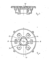
- Fig. 1 einen Schnitt längs der Linie A - A aus Figur 2 durch ein Kugelgelenk;
- Fig. 2 das Kugelgelenk nach Fig. 1 in Draufsicht;
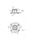
- Fig. 3 einen Schnitt durch eine andere Ausführungsform einens Kugelgelenkes längs der Linie B - B aus Fig. 4;
- Fig. 4 eine Draufsicht auf das Kugelgelenk gemäß Fig. 3;
- Fig. 5 einen Schnitt durch eine weitere Ausführungsform eines Kugelgelenkes längs der Linie C - C aus Fig. 6;
- Fig. 6 eine Draufsicht auf das Kugelgelenk gemäß Fig. 5;
- Fig. 7 einen Axialschnitt durch eine Kugelschale gemäß einer weiteren Ausführungsform;
- Fig. 8 eine Draufsicht auf die Kugelschale mit Platte gemäß Fig. 7;
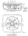
- Fig. 9 einen Schnitt durch Teile eines Kraftfahrzeugspiegels mit einem Kugelgelenk gemäß einer weiteren Ausführungsform der Erfindung längs der Linie E - E aus Fig. 10;
- Fig. 10 eine Draufsicht auf den Spiegel gemäß Fig. 9.
- Gemäß Figuren 9 und 10 weist der Kraftfahrzeug-Außenspiegel ein schalenförmiges Kunststoffgehäuse 8 auf, in dem in nicht dargestellter Weise eine motorisch oder von Hand verstellbare Spiegelglasscheibe 7 gehalten ist. Die Spiegelglasscheibe 7 wird von einem Kunststoffring 3 am Rand unterfaßt, der auf einer Spiegelglas-Trägerplatte 2 befestigt ist. Die Spiegelglas-Trägerplatte 2 ist über einem in ganzen mit 5 bezeichnetes Kugelgelenk in nicht dargestellter Weise mit dem Boden des Spiegelgehäuses 8 verbunden.
- Das Kugelgelenk 5 besteht in seiner in den Figuren 1 und 2 dargestellten Grund-Ausführung aus zwei Bauteilen, nämlich der Spiegelglas-Trägerplatte 2 und einer Kugelplatte 26. Aus der Kugelplatte 26 ist mittig eine Kugelschale 20 erhaben ausgeformt, die in diesem Ausführungsbeispiel eine zylindrische, die kugelplatte 26 durchsetzende Mittelbohrung 29 aufweist. An den beiden bezüglich der Kugelschale 20 gegenüberliegenden Seiten der Kugelplatte 26 steht parallel zur Achse 19 der Kugelschale 20 je eine Gabel 27, 28 vor, von denen jede je einen Steg 4, 6 der Trägerplatte 2 umfaßt. Die Stege 4, 6 verlaufen mit Abstand zur Oberseite der Trägerplatte 2 parallel zu dem Durchmesser 21 der Kugelschale, der senkrecht zur Achse 19 steht.
- Die Trägerplatte 2 besitzt zwischen den beiden Stegen 4, 6 in der Mitte eine herabhängende Pfanne 10 mit zylindrischer Außenkontur, in welcher die Kugelschale 20 mit ihrer Außenperipherie drehbar eingefangen ist. Aus der Innenwand der Pfanne 10 sind mehrere nach innen vorstehende Lagersegmente ausgebildet, und zwar je zur Hälfte beiderseits des Durchmessers 21 der Kugelschale 20.
- Drei erste Lagersegmente 12, 14, 16 sind über den Umfang der Pfanne 10 gleich beabstandet in einem gegenseitigen Abstand von je 1.20 Grad angeordnet und bestehen jeweils aus einer der Außenkontur der Kugelschale 20 angepaßten nach oben einwärts verlaufenden Kugelfläche, welche an dem der Oberseite der Trägerplatte 2 nahedemEnde . nach außen abgesetzt ist. Es kann aber auch eine andere Anzahl der Lagersegmente angeordnet werden.
- Ferner sind zweite Lagersegmente 13, 15, 17 unterhalb des Durchmessers 21 aus der Innenwand der Pfanne 10 nach innen vorstehend ausgebildet. Dabei erstreckt sich je ein zweites Lagersegment 13 bzw. 15 bzw. 17 umfangsmäßig zwischen je zwei benachbarten ersten Lagersegmenten 12, 14 bzw. 14, 16 bzw. 16, 12. Die zweiten lagersegmente weisen je eine der Außenkontur der Kugelschale 20 angepaßte Kugelfläche auf, welche zum unteren Rand der Pfanne 10 nach außen abgesetzt ist und nach oben über eine radial auswärts weisende Stufe 11 in einen rein zylindrischen Innenwandabschnitt der Pfanne übergeht. Entsprechend ist die Kugelfläche jedes ersten Lagersegmentes 12, 14, 16 an ihrem jeweiligen unteren Rand ebenfalls mit einer radial auswärts weisenden Stufe 11' zu einem sich weiter nach unten erstreckenden rein zylindrischen Innenwandabschnitt der Pfanne 10 abgesetzt.
- Man erkennt, daß bei der Herstellung der ersten und zweiten Lagerelemente zwei Formkerne benötigt werden, die keinerlei Hinterschnitte aufweisen.
- kann die Trägerplatte 2 ohne weiteres den beiden zusammengefügten Formhälften nach deren Öffnung entformt werdren.
- Im dargestellten Ausführungsbeispiel gemäß Figuren 1 und 2 schließen in Umfangsrichtung jeweils ein erstes Lagersegment an ein zweites Lagersegment und dieses wiederum an ein erstes Lagersegment, und so fort an. es können jedoch auch zwischen den ersten und zweiten Lagersegmenten jeweils axial durchgehende rein zylindrische Innenwandabschnitte der Pfanne 10 vorgesehen sein, wobei dann die Lagerfläche der Kugelschale 20 insgesamt kleiner wird.
- ObgLeich die Kugelschale 20 mit ihrer Axialbohrung 29 so ansgelegt werden kann, daß sie hinreichende radiale Elastizität über eine lange Lebensdauer des Kugelgelenkes 5 behält, kann es sich als zweckmäßig erweisen, der Kugelschale 20 eine nach radial außen weisende Vorspannung aufzuprägen. Hierzu sind in den weiteren Figuren verschiedene Möglichkeiten dargestellt.
- Bei der Ausführungsform gemäß Figuren 3 und 4 ist in den von der Kugelplatte 26 entferntem Teil der Bohrung 29 der Kugelschale 20 eine Gummifeder 32 eingesetzt, welche ein Nachgeben der Kugelschale 20 nach radial innen etwa aufgrund einer Ermüdung des Werkstoffes entgegenwirkt. Damit die Kugelschale 20 der durch die Gumri feder 32 ausgeübten Vorspannung folgen kann, ist die Kugelschale 20 an mehreren Stellen ihres Umfanges vom freien Ende aus mit axial gerichteten Schlitzen 22, 23, 24, 25 versehen. Statt der Gummifeder kann in das freie Ende der Bohrung 29 auch ein Federstahlring 30 eingespannt werden, der die zur Erzeugung der Vorspannung erforderliche radial gerichtete Kraft ausübt auf Figuren 5, 6.
- Andererseits ist es auch möglich, die Vorspannung durch einen Konus 40 zu erzeugen, der vom freien Ende her in die konische Blindbohrung 41 der Kugelschale 44 mittels einer Schraube 42, die sich an der Platte 26' abstützt, eingezogen werden kann. Auch diese Kugelschale 44 ist an ihrem Umfang mit mehreren axial sich erstreckenden Schlitzen 36, 37, 38, 39 versehen.Mit diesem Konus 40 ergibt sich die Möglichkeit, eine Ermüdung des Kugelschalen-Werkstoffes durch Anziehen der Schraube 42 entgegenzuwirken.
- Bei der in den Figuren 9 und 10 schließlich dargestellten Ausführungsform des Kugelgelenkes 5 ist der Konus 50 vom Äußeren des Spiegelgehäuses 8 her verstellbar. Dazu besitzt die Kugelschale-80 eine konische axiale Bohrung 81, die sich im Unterschied zur Bohrung 41 zum freien Ende der Kugelschale 80 hin verjüngt. In die Bohrung 81 ist ein Konus 50 eingesetzt, der an seiner Unterseite eine zur Achse 19 geneigte Rampe 54 aufweist. Die Kugelplatte 82 besitzt an der der Kugelschale 80 benachbarten Seite der Rampe 54 einen Ansatz 84 mit einer Durchgangsbohrung mit Innengewinde, in die eine Klemmschraube 52 mit konischem Ende eingedreht ist. Mit der Bohrung im Ansatz 84 fluchtend weist das Spiegelgehäuse 8 eine Öffnung 56 auf, sodaß durch die diese die Klemmschraube 52 von außen etwa mittels eines Schraubendrehers zugänglich ist. Durch Einwärtsdrehen der .Klemmschraube 52 wird der Konus 50 tiefer in die Bohrung 81 mit der Folge gedrängt, daß die Kugelschale 80 radial nach außen gedrückt wird. Auf diese Weise ist es möglich, ein vorgewähltes Drebmoment Spiegelglases innerhalb des Spiegelgehäuses 8 durch Nachzieben der Klemmschraube 52 zu erhöhen.
- Es versteht sich, daß auch bei den vorstehend erläuterten Ausführungsbeispielen die Kugelplatte 26 fest auf dem Boden des Spiegelgehäuses 8 aufgeschraubt oder aufgenietet ist.
- Es liegt im Rahmen der Erfindung, mehrere, beispielsweise vier Lagersegmente über den Umfang der Pfanne gleich beabstandet, beispielsweise in einem Wikelabstand von 90 Grad, anzuordnen.
Claims (9)
Priority Applications (1)
| Application Number | Priority Date | Filing Date | Title |
|---|---|---|---|
| AT85102361T ATE47983T1 (de) | 1984-05-12 | 1985-03-01 | Kraftfahrzeugspiegel, bei dem die spiegelglastr|gerplatte auf einem kugelgelenk gelagert ist. |
Applications Claiming Priority (2)
| Application Number | Priority Date | Filing Date | Title |
|---|---|---|---|
| DE8414511 | 1984-05-12 | ||
| DE8414511U | 1984-05-12 |
Publications (3)
| Publication Number | Publication Date |
|---|---|
| EP0164499A2 true EP0164499A2 (de) | 1985-12-18 |
| EP0164499A3 EP0164499A3 (en) | 1987-06-10 |
| EP0164499B1 EP0164499B1 (de) | 1989-11-15 |
Family
ID=6766801
Family Applications (1)
| Application Number | Title | Priority Date | Filing Date |
|---|---|---|---|
| EP85102361A Expired EP0164499B1 (de) | 1984-05-12 | 1985-03-01 | Kraftfahrzeugspiegel, bei dem die Spiegelglas-Trägerplatte auf einem Kugelgelenk gelagert ist |
Country Status (3)
| Country | Link |
|---|---|
| EP (1) | EP0164499B1 (de) |
| AT (1) | ATE47983T1 (de) |
| DE (1) | DE3574241D1 (de) |
Cited By (1)
| Publication number | Priority date | Publication date | Assignee | Title |
|---|---|---|---|---|
| WO2001089879A1 (es) * | 2000-05-23 | 2001-11-29 | Fico Mirrors, S.A. | Placa portaespejos para retrovisores exteriores de vehiculos automoviles |
Family Cites Families (5)
| Publication number | Priority date | Publication date | Assignee | Title |
|---|---|---|---|---|
| DE7110709U (de) * | Engelmann J | |||
| FR1448848A (fr) * | 1965-05-18 | 1966-08-12 | Cipa Comm Comptoir Inentions | Perfectionnements aux rétroviseurs extérieurs et spécialement aux rétroviseurs de portière |
| DE2931787A1 (de) * | 1979-08-04 | 1981-02-19 | Kienzle Uhrenfabriken Gmbh | Verstellvorrichtung fuer kfz-aussenrueckblickspiegel mit zwei elektromotoren |
| US4504165A (en) * | 1981-03-11 | 1985-03-12 | Regie Nationale Des Usines Renault | Ball-and-socket joint, especially for mounting the casing of an orientable rear-view mirror |
| DE3212356A1 (de) * | 1982-04-02 | 1983-10-06 | Efrudec Gmbh | Handverstellung eines antriebsblockes fuer elektromotorisch verstellbare rueckblickspiegel |
-
1985
- 1985-03-01 AT AT85102361T patent/ATE47983T1/de not_active IP Right Cessation
- 1985-03-01 EP EP85102361A patent/EP0164499B1/de not_active Expired
- 1985-03-01 DE DE8585102361T patent/DE3574241D1/de not_active Expired
Cited By (2)
| Publication number | Priority date | Publication date | Assignee | Title |
|---|---|---|---|---|
| WO2001089879A1 (es) * | 2000-05-23 | 2001-11-29 | Fico Mirrors, S.A. | Placa portaespejos para retrovisores exteriores de vehiculos automoviles |
| ES2165806A1 (es) * | 2000-05-23 | 2002-03-16 | Fico Mirrors Sa | Placa portaespejos para retrovisores exteriores de vehiculos automoviles. |
Also Published As
| Publication number | Publication date |
|---|---|
| DE3574241D1 (en) | 1989-12-21 |
| EP0164499B1 (de) | 1989-11-15 |
| ATE47983T1 (de) | 1989-12-15 |
| EP0164499A3 (en) | 1987-06-10 |
Similar Documents
| Publication | Publication Date | Title |
|---|---|---|
| DE19749137B4 (de) | Kugelumlaufspindelvorrichtung des Typs mit eingebettetem Kugelumlaufteil | |
| DE4409187A1 (de) | Vibrationsisolierender Dämpfer | |
| DE29519375U1 (de) | Kunststoff-Befestigungselement, insbesondere für eine Fahrzeugverkleidung | |
| CH666427A5 (de) | Metallspritz-giessform. | |
| DE3634383A1 (de) | Ringfoermiges maschinenteil | |
| DE69008124T2 (de) | Schutzkappe für Gabelkopf. | |
| DE69114224T2 (de) | Kombiniertes Axial-Radiallager. | |
| DE4013875A1 (de) | Verbindung eines magnetventils mit einem gehaeuseblock | |
| EP0631081B1 (de) | Anschlussvorrichtung für Rohrleitungen mit geschlitztem Klemmring | |
| DE69100826T2 (de) | Vorrichtung zum zeitweiligen Festhalten einer Achse in einem Körper, insbesondere Lenksäulenummantelung. | |
| DE29816629U1 (de) | Luftfilter | |
| DE3303685A1 (de) | Haltevorrichtung fuer eine brennraumauskleidung | |
| EP0164499B1 (de) | Kraftfahrzeugspiegel, bei dem die Spiegelglas-Trägerplatte auf einem Kugelgelenk gelagert ist | |
| DE1962687A1 (de) | System mit eingeschlossener Mutter und Kaefig | |
| DE69302894T4 (de) | Radmontage für Kraftfahrzeuge mit mindestens einer Buchse zum Positioneren des Rades auf Achsen mit verschiedenen Durchmessern | |
| DE29518501U1 (de) | Vorrichtung zum Verbinden des Ansaugstutzens einer Kraftstoffpumpe mit einem aus Kunststoff bestehenden Kraftstoffilter | |
| DE69200348T2 (de) | Halterungsherstellungsverfahren von einem rundförmigen Stück in ein rohrförmiges Stück. | |
| DE3214232A1 (de) | Rolle | |
| DE102018107083A1 (de) | Befestigungseinrichtung und Verfahren zur Befestigung eines Anbauteils an einem Tragteil, Bauteilsystem und Kraftfahrzeug | |
| DE8414511U1 (de) | Kraftfahrzeugspiegel, bei dem die Spiegelglas-Trägerplatte auf einem Kugelgelenk gelagert ist | |
| EP1043546A2 (de) | Lampenfassung für einen Fahrzeugscheinwerfer | |
| DE2604325B2 (de) | Wischvorrichtung für Scheiben von Kraftfahrzeugen | |
| DE29714671U1 (de) | Lochscheibe | |
| EP0777107B1 (de) | System zur Verbindung des Rotors eines Drehsensors mit der Welle eines Drehorgans | |
| DE4022173A1 (de) | Befestigungsvorrichtung |
Legal Events
| Date | Code | Title | Description |
|---|---|---|---|
| PUAI | Public reference made under article 153(3) epc to a published international application that has entered the european phase |
Free format text: ORIGINAL CODE: 0009012 |
|
| AK | Designated contracting states |
Designated state(s): AT BE CH DE FR GB IT LI LU NL SE |
|
| PUAL | Search report despatched |
Free format text: ORIGINAL CODE: 0009013 |
|
| AK | Designated contracting states |
Kind code of ref document: A3 Designated state(s): AT BE CH DE FR GB IT LI LU NL SE |
|
| 17P | Request for examination filed |
Effective date: 19871026 |
|
| 17Q | First examination report despatched |
Effective date: 19890419 |
|
| GRAA | (expected) grant |
Free format text: ORIGINAL CODE: 0009210 |
|
| ITF | It: translation for a ep patent filed | ||
| AK | Designated contracting states |
Kind code of ref document: B1 Designated state(s): AT BE CH DE FR GB IT LI LU NL SE |
|
| REF | Corresponds to: |
Ref document number: 47983 Country of ref document: AT Date of ref document: 19891215 Kind code of ref document: T |
|
| ET | Fr: translation filed | ||
| REF | Corresponds to: |
Ref document number: 3574241 Country of ref document: DE Date of ref document: 19891221 |
|
| GBT | Gb: translation of ep patent filed (gb section 77(6)(a)/1977) | ||
| PLBE | No opposition filed within time limit |
Free format text: ORIGINAL CODE: 0009261 |
|
| STAA | Information on the status of an ep patent application or granted ep patent |
Free format text: STATUS: NO OPPOSITION FILED WITHIN TIME LIMIT |
|
| 26N | No opposition filed | ||
| ITTA | It: last paid annual fee | ||
| PGFP | Annual fee paid to national office [announced via postgrant information from national office to epo] |
Ref country code: GB Payment date: 19940217 Year of fee payment: 10 |
|
| PGFP | Annual fee paid to national office [announced via postgrant information from national office to epo] |
Ref country code: FR Payment date: 19940318 Year of fee payment: 10 |
|
| PGFP | Annual fee paid to national office [announced via postgrant information from national office to epo] |
Ref country code: SE Payment date: 19940329 Year of fee payment: 10 Ref country code: DE Payment date: 19940329 Year of fee payment: 10 Ref country code: AT Payment date: 19940329 Year of fee payment: 10 |
|
| PGFP | Annual fee paid to national office [announced via postgrant information from national office to epo] |
Ref country code: NL Payment date: 19940331 Year of fee payment: 10 Ref country code: LU Payment date: 19940331 Year of fee payment: 10 |
|
| PGFP | Annual fee paid to national office [announced via postgrant information from national office to epo] |
Ref country code: BE Payment date: 19940413 Year of fee payment: 10 |
|
| PGFP | Annual fee paid to national office [announced via postgrant information from national office to epo] |
Ref country code: CH Payment date: 19940420 Year of fee payment: 10 |
|
| EPTA | Lu: last paid annual fee | ||
| EAL | Se: european patent in force in sweden |
Ref document number: 85102361.4 |
|
| PG25 | Lapsed in a contracting state [announced via postgrant information from national office to epo] |
Ref country code: LU Free format text: LAPSE BECAUSE OF NON-PAYMENT OF DUE FEES Effective date: 19950301 Ref country code: GB Effective date: 19950301 Ref country code: AT Effective date: 19950301 |
|
| PG25 | Lapsed in a contracting state [announced via postgrant information from national office to epo] |
Ref country code: SE Effective date: 19950302 |
|
| PG25 | Lapsed in a contracting state [announced via postgrant information from national office to epo] |
Ref country code: LI Effective date: 19950331 Ref country code: CH Effective date: 19950331 Ref country code: BE Effective date: 19950331 |
|
| BERE | Be: lapsed |
Owner name: HOHE K.G. Effective date: 19950331 |
|
| PG25 | Lapsed in a contracting state [announced via postgrant information from national office to epo] |
Ref country code: NL Effective date: 19951001 |
|
| GBPC | Gb: european patent ceased through non-payment of renewal fee |
Effective date: 19950301 |
|
| PG25 | Lapsed in a contracting state [announced via postgrant information from national office to epo] |
Ref country code: FR Free format text: LAPSE BECAUSE OF NON-PAYMENT OF DUE FEES Effective date: 19951130 |
|
| REG | Reference to a national code |
Ref country code: CH Ref legal event code: PL |
|
| NLV4 | Nl: lapsed or anulled due to non-payment of the annual fee |
Effective date: 19951001 |
|
| PG25 | Lapsed in a contracting state [announced via postgrant information from national office to epo] |
Ref country code: DE Effective date: 19951201 |
|
| EUG | Se: european patent has lapsed |
Ref document number: 85102361.4 |
|
| REG | Reference to a national code |
Ref country code: FR Ref legal event code: ST |