EP0164499A2 - Miroir d'automobile ayant une plaque de support de verre du miroir articulée sur un joint sphérique - Google Patents
Miroir d'automobile ayant une plaque de support de verre du miroir articulée sur un joint sphérique Download PDFInfo
- Publication number
- EP0164499A2 EP0164499A2 EP85102361A EP85102361A EP0164499A2 EP 0164499 A2 EP0164499 A2 EP 0164499A2 EP 85102361 A EP85102361 A EP 85102361A EP 85102361 A EP85102361 A EP 85102361A EP 0164499 A2 EP0164499 A2 EP 0164499A2
- Authority
- EP
- European Patent Office
- Prior art keywords
- spherical shell
- mirror
- bearing segments
- mirror according
- pan
- Prior art date
- Legal status (The legal status is an assumption and is not a legal conclusion. Google has not performed a legal analysis and makes no representation as to the accuracy of the status listed.)
- Granted
Links
Images


Classifications
-
- B—PERFORMING OPERATIONS; TRANSPORTING
- B60—VEHICLES IN GENERAL
- B60R—VEHICLES, VEHICLE FITTINGS, OR VEHICLE PARTS, NOT OTHERWISE PROVIDED FOR
- B60R1/00—Optical viewing arrangements; Real-time viewing arrangements for drivers or passengers using optical image capturing systems, e.g. cameras or video systems specially adapted for use in or on vehicles
- B60R1/02—Rear-view mirror arrangements
-
- F—MECHANICAL ENGINEERING; LIGHTING; HEATING; WEAPONS; BLASTING
- F16—ENGINEERING ELEMENTS AND UNITS; GENERAL MEASURES FOR PRODUCING AND MAINTAINING EFFECTIVE FUNCTIONING OF MACHINES OR INSTALLATIONS; THERMAL INSULATION IN GENERAL
- F16C—SHAFTS; FLEXIBLE SHAFTS; ELEMENTS OR CRANKSHAFT MECHANISMS; ROTARY BODIES OTHER THAN GEARING ELEMENTS; BEARINGS
- F16C11/00—Pivots; Pivotal connections
- F16C11/04—Pivotal connections
- F16C11/06—Ball-joints; Other joints having more than one degree of angular freedom, i.e. universal joints
- F16C11/0614—Ball-joints; Other joints having more than one degree of angular freedom, i.e. universal joints the female part of the joint being open on two sides
Definitions
- the invention relates to a motor vehicle mirror with a mirror housing and a mirror glass support plate which is mounted in the mirror housing via a ball joint.
- the ball joint is produced by injecting a plastic that is plastic in the heat into a two-part mold.
- the cage is created by overmolding a corresponding ball of the mold, from which the finished cage must be removed while it is still warm. By pulling off, however, the parts of the cage engaging behind the ball are stretched so far that the tight fit of the ball of the ball joint in the cage is no longer guaranteed.
- the tightness with which the ball is seated in the cage is subject to tight tolerances, because .. the ball, although rotatable, must be held in the cage in such a frictional engagement that it does not adjust itself when shaken. If the ball joint is exposed to low temperatures, the increasing brittleness of the cage material leads to fractures if the cage has been overstretched when it is removed from the molded ball.
- the ball joint consists of a pan and a spherical shell rotatably captured in the pan, and that the pan consists of a plurality of first, similar, circumferentially equally spaced bearing segments and a plurality of second, similar bearing segments, each second bearing segment being formed between adjacent first bearing segments and the second bearing segments being formed opposite the first bearing segments with respect to a diameter of the spherical shell.
- This design of the bearing segments enables the pan to be produced with shapes that have no undercuts in the area of the ball have, so that the two molds can be easily removed from the spherical segments after the injection of the plastic and sufficient cooling of the same. The pan is therefore no longer stretched when it is removed from the mold, so that no hidden cracks or overextensions can occur in the material.
- the firmness of the seat of the spherical shell in the pan is improved if the spherical shell is slotted and held under tension.
- the preload can be generated by a spring inserted into the spherical shell made of a rubber-like material or from a steel ring or by inserting a cone with a screw into the spherical shell or inserting a cone with a lower ramp against which a clamping screw acts can then be expediently accessible from the outside through an opening in the mirror housing.
- the adjustment options of the mirror glass carrier plate are controlled in a further development of the invention in that the spherical shell protrudes from a plate which carries a fork on each of two opposite sides of the spherical shell, each of which comprises a raised web firmly connected to the carrier plate, whereby the line of alignment of the two webs runs parallel to the diameter of the spherical shell.
- the motor vehicle exterior mirror has a bowl-shaped plastic housing 8, in which a mirror glass pane 7 which is adjustable by motor or by hand is held in a manner not shown.
- the mirror glass pane 7 is framed by a plastic ring 3 on the edge, which is fastened on a mirror glass carrier plate 2.
- the mirror glass support plate 2 is connected to the bottom of the mirror housing 8 in a manner not shown, via a ball joint designated as 5.
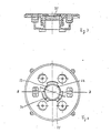
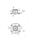
- the ball joint 5 in its basic embodiment shown in FIGS. 1 and 2 consists of two components, namely the mirror glass support plate 2 and a ball plate 26.
- a spherical shell 20 is formed in the center from the ball plate 26, which in this exemplary embodiment has a cylindrical, has the central plate 29 penetrating the ball plate 26.
- a fork 27, 28 projects parallel to the axis 19 of the spherical shell 20, each of which comprises a web 4, 6 of the carrier plate 2.
- the webs 4, 6 run at a distance from the top of the carrier plate 2 parallel to the diameter 21 of the spherical shell, which is perpendicular to the axis 19.
- the carrier plate 2 has between the two webs 4, 6 in the middle a hanging pan 10 with a cylindrical outer contour, in which the spherical shell 20 is rotatably inserted with its outer periphery catch is.
- a plurality of inwardly projecting bearing segments are formed from the inner wall of the pan 10, each half on both sides of the diameter 21 of the spherical shell 20.
- Three first bearing segments 12, 14, 16 are arranged equally spaced over the circumference of the pan 10 at a mutual distance of 1.20 degrees each and each consist of an upwardly inwardly extending spherical surface which is adapted to the outer contour of the spherical shell 20 and which is on the upper side of the carrier plate 2 near the end. is set off to the outside. However, a different number of the bearing segments can also be arranged.
- second bearing segments 13, 15, 17 are formed below the diameter 21 from the inner wall of the pan 10 projecting inwards.
- a second bearing segment 13 or 15 or 17 extends circumferentially between two adjacent first bearing segments 12, 14 or 14, 16 or 16, 12.
- the second bearing segments each have a spherical surface adapted to the outer contour of the spherical shell 20, which is offset towards the bottom of the pan 10 and merges upwards via a radially outward-pointing step 11 into a purely cylindrical inner wall section of the pan.
- the spherical surface of each first bearing segment 12, 14, 16 is also offset at its respective lower edge with a radially outward step 11 'to a purely cylindrical inner wall section of the socket 10 which extends further downward.
- the support plate 2 can easily be demolded from the two assembled mold halves after they have been opened.
- a first bearing segment each adjoins a second bearing segment in the circumferential direction and this in turn connects to a first bearing segment, and so on.
- axially continuous, purely cylindrical inner wall sections of the socket 10 can also be provided between the first and second bearing segments, the bearing surface of the spherical shell 20 then becoming smaller overall.
- the spherical shell 20 can be placed with its axial bore 29 in such a way that it retains sufficient radial elasticity over a long service life of the ball joint 5, it can prove to be expedient to impart a preload pointing radially outward to the spherical shell 20. Various possibilities for this are shown in the other figures.
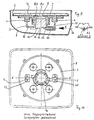
- a rubber spring 32 is inserted into the part of the bore 29 of the spherical shell 20 which is distant from the spherical plate 26 and counteracts yielding of the spherical shell 20 radially inwards, for example due to fatigue of the material. So that the spherical shell 20 can follow the preload exerted by the rubber spring 32, the spherical shell 20 is provided at several points along its circumference from the free end with axially directed slots 22, 23, 24, 25.
- a spring steel ring 30 can also be clamped into the free end of the bore 29 Applies radially directed force required to generate the preload on Figures 5, 6.
- a cone 40 which can be drawn into the conical blind bore 41 of the spherical shell 44 from the free end by means of a screw 42 which is supported on the plate 26 '.
- This spherical shell 44 is also provided on its circumference with a plurality of axially extending slots 36, 37, 38, 39.
- This cone 40 offers the possibility of counteracting fatigue of the spherical shell material by tightening the screw 42.
- the cone 50 is adjustable from the outside of the mirror housing 8.
- the spherical shell 80 has a conical axial bore 81 which, in contrast to the bore 41, tapers towards the free end of the spherical shell 80.
- a cone 50 is inserted into the bore 81 and has a ramp 54 inclined to the axis 19 on its underside.
- the ball plate 82 has on the side of the ramp 54 adjacent to the ball shell 80 a shoulder 84 with a through bore with an internal thread, into which a clamping screw 52 with a conical end is screwed.
- the mirror housing 8 Aligned with the bore in the projection 84, the mirror housing 8 has an opening 56 so that the clamping screw 52 can be accessed from the outside by means of a screwdriver, for example.
- a screwdriver for example.
- the cone 50 is pushed deeper into the bore 81, with the result that the spherical shell 80 is pressed radially outward. In this way It is possible to increase a preselected torque of mirror glass within the mirror housing 8 by tightening the clamping screw 52.
- the ball plate 26 is screwed or riveted firmly to the bottom of the mirror housing 8.
Landscapes
- Engineering & Computer Science (AREA)
- Mechanical Engineering (AREA)
- General Engineering & Computer Science (AREA)
- Multimedia (AREA)
- Rear-View Mirror Devices That Are Mounted On The Exterior Of The Vehicle (AREA)
- Optical Elements Other Than Lenses (AREA)
- Pivots And Pivotal Connections (AREA)
Priority Applications (1)
| Application Number | Priority Date | Filing Date | Title |
|---|---|---|---|
| AT85102361T ATE47983T1 (de) | 1984-05-12 | 1985-03-01 | Kraftfahrzeugspiegel, bei dem die spiegelglastr|gerplatte auf einem kugelgelenk gelagert ist. |
Applications Claiming Priority (2)
| Application Number | Priority Date | Filing Date | Title |
|---|---|---|---|
| DE8414511 | 1984-05-12 | ||
| DE8414511U | 1984-05-12 |
Publications (3)
| Publication Number | Publication Date |
|---|---|
| EP0164499A2 true EP0164499A2 (fr) | 1985-12-18 |
| EP0164499A3 EP0164499A3 (en) | 1987-06-10 |
| EP0164499B1 EP0164499B1 (fr) | 1989-11-15 |
Family
ID=6766801
Family Applications (1)
| Application Number | Title | Priority Date | Filing Date |
|---|---|---|---|
| EP85102361A Expired EP0164499B1 (fr) | 1984-05-12 | 1985-03-01 | Miroir d'automobile ayant une plaque de support de verre du miroir articulée sur un joint sphérique |
Country Status (3)
| Country | Link |
|---|---|
| EP (1) | EP0164499B1 (fr) |
| AT (1) | ATE47983T1 (fr) |
| DE (1) | DE3574241D1 (fr) |
Cited By (1)
| Publication number | Priority date | Publication date | Assignee | Title |
|---|---|---|---|---|
| WO2001089879A1 (fr) * | 2000-05-23 | 2001-11-29 | Fico Mirrors, S.A. | Plaque porte-miroir pour retroviseurs exterieurs de vehicules automobiles |
Family Cites Families (5)
| Publication number | Priority date | Publication date | Assignee | Title |
|---|---|---|---|---|
| DE7110709U (fr) * | Engelmann J | |||
| FR1448848A (fr) * | 1965-05-18 | 1966-08-12 | Cipa Comm Comptoir Inentions | Perfectionnements aux rétroviseurs extérieurs et spécialement aux rétroviseurs de portière |
| DE2931787A1 (de) * | 1979-08-04 | 1981-02-19 | Kienzle Uhrenfabriken Gmbh | Verstellvorrichtung fuer kfz-aussenrueckblickspiegel mit zwei elektromotoren |
| US4504165A (en) * | 1981-03-11 | 1985-03-12 | Regie Nationale Des Usines Renault | Ball-and-socket joint, especially for mounting the casing of an orientable rear-view mirror |
| DE3212356A1 (de) * | 1982-04-02 | 1983-10-06 | Efrudec Gmbh | Handverstellung eines antriebsblockes fuer elektromotorisch verstellbare rueckblickspiegel |
-
1985
- 1985-03-01 AT AT85102361T patent/ATE47983T1/de not_active IP Right Cessation
- 1985-03-01 EP EP85102361A patent/EP0164499B1/fr not_active Expired
- 1985-03-01 DE DE8585102361T patent/DE3574241D1/de not_active Expired
Cited By (2)
| Publication number | Priority date | Publication date | Assignee | Title |
|---|---|---|---|---|
| WO2001089879A1 (fr) * | 2000-05-23 | 2001-11-29 | Fico Mirrors, S.A. | Plaque porte-miroir pour retroviseurs exterieurs de vehicules automobiles |
| ES2165806A1 (es) * | 2000-05-23 | 2002-03-16 | Fico Mirrors Sa | Placa portaespejos para retrovisores exteriores de vehiculos automoviles. |
Also Published As
| Publication number | Publication date |
|---|---|
| DE3574241D1 (en) | 1989-12-21 |
| EP0164499B1 (fr) | 1989-11-15 |
| ATE47983T1 (de) | 1989-12-15 |
| EP0164499A3 (en) | 1987-06-10 |
Similar Documents
| Publication | Publication Date | Title |
|---|---|---|
| DE19749137B4 (de) | Kugelumlaufspindelvorrichtung des Typs mit eingebettetem Kugelumlaufteil | |
| DE4409187A1 (de) | Vibrationsisolierender Dämpfer | |
| DE29519375U1 (de) | Kunststoff-Befestigungselement, insbesondere für eine Fahrzeugverkleidung | |
| CH666427A5 (de) | Metallspritz-giessform. | |
| DE3634383A1 (de) | Ringfoermiges maschinenteil | |
| DE69008124T2 (de) | Schutzkappe für Gabelkopf. | |
| DE69114224T2 (de) | Kombiniertes Axial-Radiallager. | |
| DE4013875A1 (de) | Verbindung eines magnetventils mit einem gehaeuseblock | |
| EP0631081B1 (fr) | Dispositif de connexion pour conduites avec collier de serrage fendu | |
| DE69100826T2 (de) | Vorrichtung zum zeitweiligen Festhalten einer Achse in einem Körper, insbesondere Lenksäulenummantelung. | |
| DE29816629U1 (de) | Luftfilter | |
| DE3303685A1 (de) | Haltevorrichtung fuer eine brennraumauskleidung | |
| EP0164499B1 (fr) | Miroir d'automobile ayant une plaque de support de verre du miroir articulée sur un joint sphérique | |
| DE1962687A1 (de) | System mit eingeschlossener Mutter und Kaefig | |
| DE69302894T4 (de) | Radmontage für Kraftfahrzeuge mit mindestens einer Buchse zum Positioneren des Rades auf Achsen mit verschiedenen Durchmessern | |
| DE29518501U1 (de) | Vorrichtung zum Verbinden des Ansaugstutzens einer Kraftstoffpumpe mit einem aus Kunststoff bestehenden Kraftstoffilter | |
| DE69200348T2 (de) | Halterungsherstellungsverfahren von einem rundförmigen Stück in ein rohrförmiges Stück. | |
| DE3214232A1 (de) | Rolle | |
| DE102018107083A1 (de) | Befestigungseinrichtung und Verfahren zur Befestigung eines Anbauteils an einem Tragteil, Bauteilsystem und Kraftfahrzeug | |
| DE8414511U1 (de) | Kraftfahrzeugspiegel, bei dem die Spiegelglas-Trägerplatte auf einem Kugelgelenk gelagert ist | |
| EP1043546A2 (fr) | Dispositif formant douille de lampe dans un projecteur de véhicule | |
| DE2604325B2 (de) | Wischvorrichtung für Scheiben von Kraftfahrzeugen | |
| DE29714671U1 (de) | Lochscheibe | |
| EP0777107B1 (fr) | Système pour interconnecter un rotor d'un capteur de rotation avec un arbre d'un dispositif de rotation | |
| DE4022173A1 (de) | Befestigungsvorrichtung |
Legal Events
| Date | Code | Title | Description |
|---|---|---|---|
| PUAI | Public reference made under article 153(3) epc to a published international application that has entered the european phase |
Free format text: ORIGINAL CODE: 0009012 |
|
| AK | Designated contracting states |
Designated state(s): AT BE CH DE FR GB IT LI LU NL SE |
|
| PUAL | Search report despatched |
Free format text: ORIGINAL CODE: 0009013 |
|
| AK | Designated contracting states |
Kind code of ref document: A3 Designated state(s): AT BE CH DE FR GB IT LI LU NL SE |
|
| 17P | Request for examination filed |
Effective date: 19871026 |
|
| 17Q | First examination report despatched |
Effective date: 19890419 |
|
| GRAA | (expected) grant |
Free format text: ORIGINAL CODE: 0009210 |
|
| ITF | It: translation for a ep patent filed | ||
| AK | Designated contracting states |
Kind code of ref document: B1 Designated state(s): AT BE CH DE FR GB IT LI LU NL SE |
|
| REF | Corresponds to: |
Ref document number: 47983 Country of ref document: AT Date of ref document: 19891215 Kind code of ref document: T |
|
| ET | Fr: translation filed | ||
| REF | Corresponds to: |
Ref document number: 3574241 Country of ref document: DE Date of ref document: 19891221 |
|
| GBT | Gb: translation of ep patent filed (gb section 77(6)(a)/1977) | ||
| PLBE | No opposition filed within time limit |
Free format text: ORIGINAL CODE: 0009261 |
|
| STAA | Information on the status of an ep patent application or granted ep patent |
Free format text: STATUS: NO OPPOSITION FILED WITHIN TIME LIMIT |
|
| 26N | No opposition filed | ||
| ITTA | It: last paid annual fee | ||
| PGFP | Annual fee paid to national office [announced via postgrant information from national office to epo] |
Ref country code: GB Payment date: 19940217 Year of fee payment: 10 |
|
| PGFP | Annual fee paid to national office [announced via postgrant information from national office to epo] |
Ref country code: FR Payment date: 19940318 Year of fee payment: 10 |
|
| PGFP | Annual fee paid to national office [announced via postgrant information from national office to epo] |
Ref country code: SE Payment date: 19940329 Year of fee payment: 10 Ref country code: DE Payment date: 19940329 Year of fee payment: 10 Ref country code: AT Payment date: 19940329 Year of fee payment: 10 |
|
| PGFP | Annual fee paid to national office [announced via postgrant information from national office to epo] |
Ref country code: NL Payment date: 19940331 Year of fee payment: 10 Ref country code: LU Payment date: 19940331 Year of fee payment: 10 |
|
| PGFP | Annual fee paid to national office [announced via postgrant information from national office to epo] |
Ref country code: BE Payment date: 19940413 Year of fee payment: 10 |
|
| PGFP | Annual fee paid to national office [announced via postgrant information from national office to epo] |
Ref country code: CH Payment date: 19940420 Year of fee payment: 10 |
|
| EPTA | Lu: last paid annual fee | ||
| EAL | Se: european patent in force in sweden |
Ref document number: 85102361.4 |
|
| PG25 | Lapsed in a contracting state [announced via postgrant information from national office to epo] |
Ref country code: LU Free format text: LAPSE BECAUSE OF NON-PAYMENT OF DUE FEES Effective date: 19950301 Ref country code: GB Effective date: 19950301 Ref country code: AT Effective date: 19950301 |
|
| PG25 | Lapsed in a contracting state [announced via postgrant information from national office to epo] |
Ref country code: SE Effective date: 19950302 |
|
| PG25 | Lapsed in a contracting state [announced via postgrant information from national office to epo] |
Ref country code: LI Effective date: 19950331 Ref country code: CH Effective date: 19950331 Ref country code: BE Effective date: 19950331 |
|
| BERE | Be: lapsed |
Owner name: HOHE K.G. Effective date: 19950331 |
|
| PG25 | Lapsed in a contracting state [announced via postgrant information from national office to epo] |
Ref country code: NL Effective date: 19951001 |
|
| GBPC | Gb: european patent ceased through non-payment of renewal fee |
Effective date: 19950301 |
|
| PG25 | Lapsed in a contracting state [announced via postgrant information from national office to epo] |
Ref country code: FR Free format text: LAPSE BECAUSE OF NON-PAYMENT OF DUE FEES Effective date: 19951130 |
|
| REG | Reference to a national code |
Ref country code: CH Ref legal event code: PL |
|
| NLV4 | Nl: lapsed or anulled due to non-payment of the annual fee |
Effective date: 19951001 |
|
| PG25 | Lapsed in a contracting state [announced via postgrant information from national office to epo] |
Ref country code: DE Effective date: 19951201 |
|
| EUG | Se: european patent has lapsed |
Ref document number: 85102361.4 |
|
| REG | Reference to a national code |
Ref country code: FR Ref legal event code: ST |