EP0164623B1 - Glasfaserendoskop mit Biegemechanismus - Google Patents
Glasfaserendoskop mit Biegemechanismus Download PDFInfo
- Publication number
- EP0164623B1 EP0164623B1 EP85106294A EP85106294A EP0164623B1 EP 0164623 B1 EP0164623 B1 EP 0164623B1 EP 85106294 A EP85106294 A EP 85106294A EP 85106294 A EP85106294 A EP 85106294A EP 0164623 B1 EP0164623 B1 EP 0164623B1
- Authority
- EP
- European Patent Office
- Prior art keywords
- tip
- fiberscope
- tube
- section
- cover tube
- Prior art date
- Legal status (The legal status is an assumption and is not a legal conclusion. Google has not performed a legal analysis and makes no representation as to the accuracy of the status listed.)
- Expired
Links
Images

Classifications
-
- A—HUMAN NECESSITIES
- A61—MEDICAL OR VETERINARY SCIENCE; HYGIENE
- A61B—DIAGNOSIS; SURGERY; IDENTIFICATION
- A61B1/00—Instruments for performing medical examinations of the interior of cavities or tubes of the body by visual or photographical inspection, e.g. endoscopes; Illuminating arrangements therefor
- A61B1/005—Flexible endoscopes
- A61B1/0051—Flexible endoscopes with controlled bending of insertion part
-
- A—HUMAN NECESSITIES
- A61—MEDICAL OR VETERINARY SCIENCE; HYGIENE
- A61B—DIAGNOSIS; SURGERY; IDENTIFICATION
- A61B1/00—Instruments for performing medical examinations of the interior of cavities or tubes of the body by visual or photographical inspection, e.g. endoscopes; Illuminating arrangements therefor
- A61B1/00064—Constructional details of the endoscope body
- A61B1/00071—Insertion part of the endoscope body
- A61B1/0008—Insertion part of the endoscope body characterised by distal tip features
- A61B1/00082—Balloons
-
- A—HUMAN NECESSITIES
- A61—MEDICAL OR VETERINARY SCIENCE; HYGIENE
- A61B—DIAGNOSIS; SURGERY; IDENTIFICATION
- A61B1/00—Instruments for performing medical examinations of the interior of cavities or tubes of the body by visual or photographical inspection, e.g. endoscopes; Illuminating arrangements therefor
- A61B1/005—Flexible endoscopes
- A61B1/0051—Flexible endoscopes with controlled bending of insertion part
- A61B1/0055—Constructional details of insertion parts, e.g. vertebral elements
-
- G—PHYSICS
- G02—OPTICS
- G02B—OPTICAL ELEMENTS, SYSTEMS OR APPARATUS
- G02B23/00—Telescopes, e.g. binoculars; Periscopes; Instruments for viewing the inside of hollow bodies; Viewfinders; Optical aiming or sighting devices
- G02B23/24—Instruments or systems for viewing the inside of hollow bodies, e.g. fibrescopes
- G02B23/26—Instruments or systems for viewing the inside of hollow bodies, e.g. fibrescopes using light guides
-
- A—HUMAN NECESSITIES
- A61—MEDICAL OR VETERINARY SCIENCE; HYGIENE
- A61B—DIAGNOSIS; SURGERY; IDENTIFICATION
- A61B1/00—Instruments for performing medical examinations of the interior of cavities or tubes of the body by visual or photographical inspection, e.g. endoscopes; Illuminating arrangements therefor
- A61B1/00163—Optical arrangements
- A61B1/00165—Optical arrangements with light-conductive means, e.g. fibre optics
-
- A—HUMAN NECESSITIES
- A61—MEDICAL OR VETERINARY SCIENCE; HYGIENE
- A61B—DIAGNOSIS; SURGERY; IDENTIFICATION
- A61B1/00—Instruments for performing medical examinations of the interior of cavities or tubes of the body by visual or photographical inspection, e.g. endoscopes; Illuminating arrangements therefor
- A61B1/06—Instruments for performing medical examinations of the interior of cavities or tubes of the body by visual or photographical inspection, e.g. endoscopes; Illuminating arrangements therefor with illuminating arrangements
- A61B1/07—Instruments for performing medical examinations of the interior of cavities or tubes of the body by visual or photographical inspection, e.g. endoscopes; Illuminating arrangements therefor with illuminating arrangements using light-conductive means, e.g. optical fibres
Definitions
- the invention relates to a fibrescope according to the generic clause of claim 1.
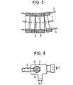
- FIG. 5 A conventional mechanism for meeting this requirement is illustrated by Fig. 5. As seen in said drawing an image fiber is surrounded by a plurality of node rings 2 which are caused to abut against each other with an intervening central spherical fulcrum 3. Manipulating wires 4 are inserted through the ring nodes 2. The manipulating wires are controlled by the mechanism shown in Fig. 6 so as to permit free bending of the image fiber 1.
- a fiberscope having the features of the precharacterizing clause of claim 1 is disclosed in the US-A-3583393.
- This fiberscope uses a bendable tube assembly comprised of a plurality of thin walled cylindrical segments arranged in series endwise to each other. The end edge of the segments is bevelled starting from diametrically opposed two points in the end edge so that two diametrically opposed raised portions are formed in the end edge thereby permitting the series of the segments connected endwise to each other to be bent.
- the object underlying the present invention is therefore to fabricate a very fine fiberscope having an easy construction particularly for bending mechanism.
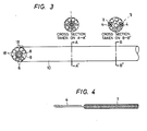
- FIG. 1 A preferred embodiment of a fiberscope of the present invention is shown in Figs. 1 to 4.
- This fiberscope is especially designed for viewing the inner walls of the heart.
- a transparent balloon 5 is provided at the forward end of the fiberscope as shown in Fig. 1.
- the internal components of the scope are an image fiber 1, light-guiding plastic fiber bundles 18, and balloon expanding or contracting tubes 6.
- a sleeve 8 At the tip of the image fiber 1 is provided a sleeve 8 which is connected to an imaging lens 9.
- two manipulating wires 4 sheathed in tubes in a coil form 7 are provided diametrically in the cross section of the fiber.
- the tubes 7 are made of a material such as stainless-steel that ensures good slip on the manipulating wires 4.
- the device shown in Fig. 1 (which does not show the image fiber and light guide), has an assembly of elements 17 (including the imaging lens parts of the image fiber the light guide and the balloon expanding or contracting tubes 6 and other tip-forming elements) that are cast and fixed in an epoxy resin or other suitable materials, thereby providing a tip. cast section 10.
- the tubes 7 in a coil form extend halfway through an intermediate cast section 14 and only the manipulating wires 4 extend to the tip cast section 10.
- the tip of each manipulating wire 4 is folded back and fixed within the tip cast section.
- the intermediate cast section 14 is spaced from the tip cast section and has the image fiber and the light guide cast and fixed therein. The image fiber and the light guide is held free between the two cast portions.
- That part of the image fiber which is between these two cast sections is covered with a rubber tube 15 made of silicone rubber or other material that satisfy the requirements: (1) sufficient resiliency to provide an adequate resistance against the bending forces exerted by manipulation with the wires 4, and (2) sufficient resiliency to provide an adequate resistance against radial expansion of the image fiber, the light guide and said tube 6.
- the outer diameter of the cable section of the fiberscope in accordance with the present invention can be reduced to a dimension as small as 2.8 mm.
- the manipulating wires 4 have outside and inside diameters of approximately 0.53 mm and 0.19 mm, respectively.
- the bending mechanism incorporated in the scope of the present invention permits free bending through ⁇ 45° under a tension of about 1.4 kg.
- Fig. 2 shows the construction of the forward portion of the fiberscope in accordance with the present invention
- Fig. 3 illustrates the construction of the tip cast section 10.
- the inner surfaces of the tubes 7 in coil form may be coated with a polyethylene tetrafluoride resin such as Teflon R. Bending in more than two directions may be achieved by using a greater number of manipulating wires.
- the fiberscope of the present invention replaces the conventionally used node rings by a flexible rubber tube that provides an outer cover for bending section and through which the manipulating wires are inserted.
- the bending mechanism incorporated in the fiberscope does not result in an increase in diameter; instead, this mechanism contributes to a reduction in the cost and weight of the bending portion.
Landscapes
- Health & Medical Sciences (AREA)
- Life Sciences & Earth Sciences (AREA)
- Surgery (AREA)
- Physics & Mathematics (AREA)
- Optics & Photonics (AREA)
- Biomedical Technology (AREA)
- Animal Behavior & Ethology (AREA)
- Radiology & Medical Imaging (AREA)
- Nuclear Medicine, Radiotherapy & Molecular Imaging (AREA)
- Engineering & Computer Science (AREA)
- Biophysics (AREA)
- Heart & Thoracic Surgery (AREA)
- Medical Informatics (AREA)
- Molecular Biology (AREA)
- Pathology (AREA)
- General Health & Medical Sciences (AREA)
- Public Health (AREA)
- Veterinary Medicine (AREA)
- Astronomy & Astrophysics (AREA)
- General Physics & Mathematics (AREA)
- Endoscopes (AREA)
- Instruments For Viewing The Inside Of Hollow Bodies (AREA)
Claims (7)
Applications Claiming Priority (2)
| Application Number | Priority Date | Filing Date | Title |
|---|---|---|---|
| JP59112123A JPS60253428A (ja) | 1984-05-30 | 1984-05-30 | 屈曲機構付フアイバスコ−プ |
| JP112123/84 | 1984-05-30 |
Publications (2)
| Publication Number | Publication Date |
|---|---|
| EP0164623A1 EP0164623A1 (de) | 1985-12-18 |
| EP0164623B1 true EP0164623B1 (de) | 1989-08-30 |
Family
ID=14578765
Family Applications (1)
| Application Number | Title | Priority Date | Filing Date |
|---|---|---|---|
| EP85106294A Expired EP0164623B1 (de) | 1984-05-30 | 1985-05-22 | Glasfaserendoskop mit Biegemechanismus |
Country Status (7)
| Country | Link |
|---|---|
| US (1) | US4708434A (de) |
| EP (1) | EP0164623B1 (de) |
| JP (1) | JPS60253428A (de) |
| KR (2) | KR850008413A (de) |
| AU (1) | AU573833B2 (de) |
| CA (1) | CA1258840A (de) |
| DE (1) | DE3572586D1 (de) |
Families Citing this family (69)
| Publication number | Priority date | Publication date | Assignee | Title |
|---|---|---|---|---|
| US4776667A (en) * | 1981-06-20 | 1988-10-11 | Sumitomo Electric Industries, Ltd. | Image transmission line |
| JPS6365413A (ja) * | 1986-09-08 | 1988-03-24 | Sumitomo Electric Ind Ltd | 屈曲機構を備えた光学的ケ−ブル |
| EP0288833A1 (de) * | 1987-04-30 | 1988-11-02 | Inc. Advanced Cardiovascular Systems | Ballondilatationskatheter, geeignet zum Laserschneiden |
| AU611894B2 (en) * | 1987-04-30 | 1991-06-27 | Advanced Cardiovascular Systems Inc. | Imaging balloon dilatation catheter |
| JPH0792549B2 (ja) * | 1987-08-10 | 1995-10-09 | 富士写真光機株式会社 | 内視鏡の作動部材操作装置 |
| JPH0664239B2 (ja) * | 1987-09-14 | 1994-08-22 | 株式会社フジクラ | ファイバスコープの首振り装置 |
| JP2717540B2 (ja) * | 1988-02-22 | 1998-02-18 | 日産テクシス株式会社 | 流体噴射式織機における緯糸のノズル抜け防止方法 |
| JPH01226838A (ja) * | 1988-03-08 | 1989-09-11 | Mitsubishi Kasei Corp | センブラン型ジテルペン化合物 |
| JPH063521Y2 (ja) * | 1988-03-22 | 1994-02-02 | 三菱電線工業株式会社 | ファイバスコープ |
| JPH0724264B2 (ja) * | 1988-03-23 | 1995-03-15 | 日本電気株式会社 | 半導体基板水洗装置 |
| JPH065762Y2 (ja) * | 1988-04-19 | 1994-02-16 | 三菱電線工業株式会社 | 内視鏡 |
| JPH065763Y2 (ja) * | 1988-05-28 | 1994-02-16 | 三菱電線工業株式会社 | カテーテル形ファイバスコープ |
| US4899732A (en) * | 1988-09-02 | 1990-02-13 | Baxter International, Inc. | Miniscope |
| JPH0773566B2 (ja) * | 1990-06-06 | 1995-08-09 | 三菱電線工業株式会社 | 極細径首振り内視鏡 |
| US5370108A (en) * | 1991-10-02 | 1994-12-06 | Asahi Kogaku Kogyo Kabushiki Kaisha | Endoscope |
| US6200311B1 (en) | 1998-01-20 | 2001-03-13 | Eclipse Surgical Technologies, Inc. | Minimally invasive TMR device |
| US5984860A (en) * | 1998-03-25 | 1999-11-16 | Shan; Yansong | Pass-through duodenal enteroscopic device |
| WO2002007611A2 (en) * | 2000-07-21 | 2002-01-31 | Atropos Limited | A surgical instrument |
| DE10105592A1 (de) | 2001-02-06 | 2002-08-08 | Achim Goepferich | Platzhalter zur Arzneistofffreigabe in der Stirnhöhle |
| US20060199999A1 (en) * | 2001-06-29 | 2006-09-07 | Intuitive Surgical Inc. | Cardiac tissue ablation instrument with flexible wrist |
| US6817974B2 (en) | 2001-06-29 | 2004-11-16 | Intuitive Surgical, Inc. | Surgical tool having positively positionable tendon-actuated multi-disk wrist joint |
| US20060178556A1 (en) | 2001-06-29 | 2006-08-10 | Intuitive Surgical, Inc. | Articulate and swapable endoscope for a surgical robot |
| US8317816B2 (en) | 2002-09-30 | 2012-11-27 | Acclarent, Inc. | Balloon catheters and methods for treating paranasal sinuses |
| EP2359768B1 (de) | 2002-12-06 | 2018-10-03 | Intuitive Surgical Operations, Inc. | Flexibles Gelenk für ein Operationsinstrument |
| US7410480B2 (en) * | 2004-04-21 | 2008-08-12 | Acclarent, Inc. | Devices and methods for delivering therapeutic substances for the treatment of sinusitis and other disorders |
| US8894614B2 (en) | 2004-04-21 | 2014-11-25 | Acclarent, Inc. | Devices, systems and methods useable for treating frontal sinusitis |
| US8747389B2 (en) | 2004-04-21 | 2014-06-10 | Acclarent, Inc. | Systems for treating disorders of the ear, nose and throat |
| US8146400B2 (en) | 2004-04-21 | 2012-04-03 | Acclarent, Inc. | Endoscopic methods and devices for transnasal procedures |
| US20190314620A1 (en) | 2004-04-21 | 2019-10-17 | Acclarent, Inc. | Apparatus and methods for dilating and modifying ostia of paranasal sinuses and other intranasal or paranasal structures |
| US20060063973A1 (en) | 2004-04-21 | 2006-03-23 | Acclarent, Inc. | Methods and apparatus for treating disorders of the ear, nose and throat |
| US7803150B2 (en) | 2004-04-21 | 2010-09-28 | Acclarent, Inc. | Devices, systems and methods useable for treating sinusitis |
| US20070208252A1 (en) | 2004-04-21 | 2007-09-06 | Acclarent, Inc. | Systems and methods for performing image guided procedures within the ear, nose, throat and paranasal sinuses |
| US7462175B2 (en) | 2004-04-21 | 2008-12-09 | Acclarent, Inc. | Devices, systems and methods for treating disorders of the ear, nose and throat |
| US7559925B2 (en) | 2006-09-15 | 2009-07-14 | Acclarent Inc. | Methods and devices for facilitating visualization in a surgical environment |
| US7720521B2 (en) | 2004-04-21 | 2010-05-18 | Acclarent, Inc. | Methods and devices for performing procedures within the ear, nose, throat and paranasal sinuses |
| US9554691B2 (en) | 2004-04-21 | 2017-01-31 | Acclarent, Inc. | Endoscopic methods and devices for transnasal procedures |
| US10188413B1 (en) | 2004-04-21 | 2019-01-29 | Acclarent, Inc. | Deflectable guide catheters and related methods |
| US7361168B2 (en) | 2004-04-21 | 2008-04-22 | Acclarent, Inc. | Implantable device and methods for delivering drugs and other substances to treat sinusitis and other disorders |
| US9351750B2 (en) | 2004-04-21 | 2016-05-31 | Acclarent, Inc. | Devices and methods for treating maxillary sinus disease |
| US9089258B2 (en) | 2004-04-21 | 2015-07-28 | Acclarent, Inc. | Endoscopic methods and devices for transnasal procedures |
| US8864787B2 (en) | 2004-04-21 | 2014-10-21 | Acclarent, Inc. | Ethmoidotomy system and implantable spacer devices having therapeutic substance delivery capability for treatment of paranasal sinusitis |
| US8764729B2 (en) | 2004-04-21 | 2014-07-01 | Acclarent, Inc. | Frontal sinus spacer |
| US20060004323A1 (en) | 2004-04-21 | 2006-01-05 | Exploramed Nc1, Inc. | Apparatus and methods for dilating and modifying ostia of paranasal sinuses and other intranasal or paranasal structures |
| US8932276B1 (en) | 2004-04-21 | 2015-01-13 | Acclarent, Inc. | Shapeable guide catheters and related methods |
| US20070167682A1 (en) | 2004-04-21 | 2007-07-19 | Acclarent, Inc. | Endoscopic methods and devices for transnasal procedures |
| US8702626B1 (en) | 2004-04-21 | 2014-04-22 | Acclarent, Inc. | Guidewires for performing image guided procedures |
| US9101384B2 (en) | 2004-04-21 | 2015-08-11 | Acclarent, Inc. | Devices, systems and methods for diagnosing and treating sinusitis and other disorders of the ears, Nose and/or throat |
| US7654997B2 (en) | 2004-04-21 | 2010-02-02 | Acclarent, Inc. | Devices, systems and methods for diagnosing and treating sinusitus and other disorders of the ears, nose and/or throat |
| US7419497B2 (en) | 2004-04-21 | 2008-09-02 | Acclarent, Inc. | Methods for treating ethmoid disease |
| US9399121B2 (en) | 2004-04-21 | 2016-07-26 | Acclarent, Inc. | Systems and methods for transnasal dilation of passageways in the ear, nose or throat |
| US8951225B2 (en) | 2005-06-10 | 2015-02-10 | Acclarent, Inc. | Catheters with non-removable guide members useable for treatment of sinusitis |
| US8114113B2 (en) | 2005-09-23 | 2012-02-14 | Acclarent, Inc. | Multi-conduit balloon catheter |
| US8190389B2 (en) | 2006-05-17 | 2012-05-29 | Acclarent, Inc. | Adapter for attaching electromagnetic image guidance components to a medical device |
| US9820688B2 (en) | 2006-09-15 | 2017-11-21 | Acclarent, Inc. | Sinus illumination lightwire device |
| US8439687B1 (en) | 2006-12-29 | 2013-05-14 | Acclarent, Inc. | Apparatus and method for simulated insertion and positioning of guidewares and other interventional devices |
| US8118757B2 (en) | 2007-04-30 | 2012-02-21 | Acclarent, Inc. | Methods and devices for ostium measurement |
| US8485199B2 (en) | 2007-05-08 | 2013-07-16 | Acclarent, Inc. | Methods and devices for protecting nasal turbinate during surgery |
| US10206821B2 (en) | 2007-12-20 | 2019-02-19 | Acclarent, Inc. | Eustachian tube dilation balloon with ventilation path |
| US8182432B2 (en) | 2008-03-10 | 2012-05-22 | Acclarent, Inc. | Corewire design and construction for medical devices |
| ES2700863T3 (es) | 2008-07-30 | 2019-02-19 | Acclarent Inc | Dispositivos de localización del ostium paranasal |
| EP2323724A1 (de) | 2008-09-18 | 2011-05-25 | Acclarent, Inc. | Verfahren und gerät zur behandlung von erkrankungen von hals, nase und ohren |
| US20100241155A1 (en) | 2009-03-20 | 2010-09-23 | Acclarent, Inc. | Guide system with suction |
| US8435290B2 (en) | 2009-03-31 | 2013-05-07 | Acclarent, Inc. | System and method for treatment of non-ventilating middle ear by providing a gas pathway through the nasopharynx |
| US7978742B1 (en) | 2010-03-24 | 2011-07-12 | Corning Incorporated | Methods for operating diode lasers |
| US9155492B2 (en) | 2010-09-24 | 2015-10-13 | Acclarent, Inc. | Sinus illumination lightwire device |
| US9211134B2 (en) | 2012-04-09 | 2015-12-15 | Carefusion 2200, Inc. | Wrist assembly for articulating laparoscopic surgical instruments |
| US9629684B2 (en) | 2013-03-15 | 2017-04-25 | Acclarent, Inc. | Apparatus and method for treatment of ethmoid sinusitis |
| US9433437B2 (en) | 2013-03-15 | 2016-09-06 | Acclarent, Inc. | Apparatus and method for treatment of ethmoid sinusitis |
| EP3648653B1 (de) * | 2017-10-25 | 2023-05-10 | Boston Scientific Scimed Inc. | Katheter mit direkter visualisierung und system |
Family Cites Families (11)
| Publication number | Priority date | Publication date | Assignee | Title |
|---|---|---|---|---|
| DE1102341B (de) * | 1960-09-29 | 1961-03-16 | Karl Storz | OEsophagoskop |
| US3416531A (en) * | 1964-01-02 | 1968-12-17 | Edwards Miles Lowell | Catheter |
| US3610231A (en) * | 1967-07-21 | 1971-10-05 | Olympus Optical Co | Endoscope |
| US3583393A (en) * | 1967-12-26 | 1971-06-08 | Olympus Optical Co | Bendable tube assembly |
| US3572325A (en) * | 1968-10-25 | 1971-03-23 | Us Health Education & Welfare | Flexible endoscope having fluid conduits and control |
| US3690769A (en) * | 1969-12-12 | 1972-09-12 | Olympus Optical Co | Endoscope with built-in oximeter |
| US3788304A (en) * | 1971-06-15 | 1974-01-29 | Olympus Optical Co | Endoscope |
| JPS5243693Y2 (de) * | 1972-06-15 | 1977-10-04 | ||
| JPS576241Y2 (de) * | 1973-08-31 | 1982-02-05 | ||
| JPS59124312A (ja) * | 1982-12-29 | 1984-07-18 | Sumitomo Electric Ind Ltd | 画像観察装置 |
| US4569335A (en) * | 1983-04-12 | 1986-02-11 | Sumitomo Electric Industries, Ltd. | Fiberscope |
-
1984
- 1984-05-30 JP JP59112123A patent/JPS60253428A/ja active Pending
-
1985
- 1985-05-14 KR KR1019850003264A patent/KR850008413A/ko not_active Withdrawn
- 1985-05-22 DE DE8585106294T patent/DE3572586D1/de not_active Expired
- 1985-05-22 EP EP85106294A patent/EP0164623B1/de not_active Expired
- 1985-05-27 AU AU42887/85A patent/AU573833B2/en not_active Ceased
- 1985-05-30 CA CA000482846A patent/CA1258840A/en not_active Expired
- 1985-05-30 US US06/739,258 patent/US4708434A/en not_active Expired - Fee Related
-
1990
- 1990-03-09 KR KR2019900002774U patent/KR900003922Y1/ko not_active Expired
Also Published As
| Publication number | Publication date |
|---|---|
| CA1258840A (en) | 1989-08-29 |
| KR850008413A (ko) | 1985-12-16 |
| KR900003922Y1 (ko) | 1990-05-04 |
| EP0164623A1 (de) | 1985-12-18 |
| US4708434A (en) | 1987-11-24 |
| DE3572586D1 (en) | 1989-10-05 |
| AU4288785A (en) | 1985-12-05 |
| JPS60253428A (ja) | 1985-12-14 |
| AU573833B2 (en) | 1988-06-23 |
Similar Documents
| Publication | Publication Date | Title |
|---|---|---|
| US4708434A (en) | Fiberscope with bending mechanism | |
| US4770188A (en) | Guide tube assembly for an endoscope | |
| US5683348A (en) | Endoscope | |
| EP0422842B1 (de) | Biegevorrichtung | |
| US4805595A (en) | Flexible tube assembly for endoscope | |
| US5449021A (en) | Bending device | |
| US5386816A (en) | Endoscope | |
| US5307803A (en) | Deflecting endoscope | |
| JPH069540B2 (ja) | 内視鏡 | |
| EP0996016A3 (de) | Lichtwellenleiterkabel | |
| US4336794A (en) | Guide tube | |
| JP2875583B2 (ja) | 湾曲操作装置用湾曲部 | |
| US4826281A (en) | Optical cable with bending mechanism | |
| JPH0434496Y2 (de) | ||
| JPH0876026A (ja) | 内視鏡 | |
| JP3220928B2 (ja) | 内視鏡 | |
| JP2011120687A (ja) | 内視鏡挿入部 | |
| JPH0546723Y2 (de) | ||
| JPS6330404Y2 (de) | ||
| JPH08252214A (ja) | 内視鏡の湾曲部 | |
| JP2001137178A (ja) | 内視鏡 | |
| JPS63154151A (ja) | 内視鏡 | |
| JPH0432082Y2 (de) | ||
| JPH0117284Y2 (de) | ||
| JPH02109537A (ja) | 内視鏡の湾曲部装置 |
Legal Events
| Date | Code | Title | Description |
|---|---|---|---|
| PUAI | Public reference made under article 153(3) epc to a published international application that has entered the european phase |
Free format text: ORIGINAL CODE: 0009012 |
|
| AK | Designated contracting states |
Designated state(s): DE FR GB IT NL SE |
|
| 16A | New documents despatched to applicant after publication of the search report | ||
| 17P | Request for examination filed |
Effective date: 19860305 |
|
| 17Q | First examination report despatched |
Effective date: 19870812 |
|
| GRAA | (expected) grant |
Free format text: ORIGINAL CODE: 0009210 |
|
| AK | Designated contracting states |
Kind code of ref document: B1 Designated state(s): DE FR GB IT NL SE |
|
| REF | Corresponds to: |
Ref document number: 3572586 Country of ref document: DE Date of ref document: 19891005 |
|
| ITF | It: translation for a ep patent filed | ||
| ET | Fr: translation filed | ||
| PLBE | No opposition filed within time limit |
Free format text: ORIGINAL CODE: 0009261 |
|
| STAA | Information on the status of an ep patent application or granted ep patent |
Free format text: STATUS: NO OPPOSITION FILED WITHIN TIME LIMIT |
|
| 26N | No opposition filed | ||
| ITTA | It: last paid annual fee | ||
| EAL | Se: european patent in force in sweden |
Ref document number: 85106294.3 |
|
| PGFP | Annual fee paid to national office [announced via postgrant information from national office to epo] |
Ref country code: FR Payment date: 19960510 Year of fee payment: 12 |
|
| PGFP | Annual fee paid to national office [announced via postgrant information from national office to epo] |
Ref country code: GB Payment date: 19960513 Year of fee payment: 12 |
|
| PGFP | Annual fee paid to national office [announced via postgrant information from national office to epo] |
Ref country code: SE Payment date: 19960517 Year of fee payment: 12 |
|
| PGFP | Annual fee paid to national office [announced via postgrant information from national office to epo] |
Ref country code: DE Payment date: 19960528 Year of fee payment: 12 |
|
| PGFP | Annual fee paid to national office [announced via postgrant information from national office to epo] |
Ref country code: NL Payment date: 19960529 Year of fee payment: 12 |
|
| PG25 | Lapsed in a contracting state [announced via postgrant information from national office to epo] |
Ref country code: GB Effective date: 19970522 |
|
| PG25 | Lapsed in a contracting state [announced via postgrant information from national office to epo] |
Ref country code: SE Effective date: 19970523 |
|
| PG25 | Lapsed in a contracting state [announced via postgrant information from national office to epo] |
Ref country code: NL Effective date: 19971201 |
|
| GBPC | Gb: european patent ceased through non-payment of renewal fee |
Effective date: 19970522 |
|
| PG25 | Lapsed in a contracting state [announced via postgrant information from national office to epo] |
Ref country code: FR Free format text: LAPSE BECAUSE OF NON-PAYMENT OF DUE FEES Effective date: 19980130 |
|
| EUG | Se: european patent has lapsed |
Ref document number: 85106294.3 |
|
| NLV4 | Nl: lapsed or anulled due to non-payment of the annual fee |
Effective date: 19971201 |
|
| PG25 | Lapsed in a contracting state [announced via postgrant information from national office to epo] |
Ref country code: DE Free format text: LAPSE BECAUSE OF NON-PAYMENT OF DUE FEES Effective date: 19980203 |
|
| REG | Reference to a national code |
Ref country code: FR Ref legal event code: ST |