EP0164648B1 - Vorrichtung und Verfahren zur Orientierung von durchgebohrten Stumpfkonen und/oder von zylindrischen Körpern, wie z.B. Garnspulen oder Konen in Masse angeliefert - Google Patents
Vorrichtung und Verfahren zur Orientierung von durchgebohrten Stumpfkonen und/oder von zylindrischen Körpern, wie z.B. Garnspulen oder Konen in Masse angeliefert Download PDFInfo
- Publication number
- EP0164648B1 EP0164648B1 EP85106598A EP85106598A EP0164648B1 EP 0164648 B1 EP0164648 B1 EP 0164648B1 EP 85106598 A EP85106598 A EP 85106598A EP 85106598 A EP85106598 A EP 85106598A EP 0164648 B1 EP0164648 B1 EP 0164648B1
- Authority
- EP
- European Patent Office
- Prior art keywords
- axis
- bodies
- channel
- frusto
- conical
- Prior art date
- Legal status (The legal status is an assumption and is not a legal conclusion. Google has not performed a legal analysis and makes no representation as to the accuracy of the status listed.)
- Expired
Links
- 238000000034 method Methods 0.000 title claims description 13
- 238000001514 detection method Methods 0.000 claims 1
- 230000005484 gravity Effects 0.000 claims 1
- 238000011144 upstream manufacturing Methods 0.000 description 2
- 238000000151 deposition Methods 0.000 description 1
- 238000004043 dyeing Methods 0.000 description 1
- 238000005096 rolling process Methods 0.000 description 1
- 238000004804 winding Methods 0.000 description 1
Images




Classifications
-
- B—PERFORMING OPERATIONS; TRANSPORTING
- B65—CONVEYING; PACKING; STORING; HANDLING THIN OR FILAMENTARY MATERIAL
- B65G—TRANSPORT OR STORAGE DEVICES, e.g. CONVEYORS FOR LOADING OR TIPPING, SHOP CONVEYOR SYSTEMS OR PNEUMATIC TUBE CONVEYORS
- B65G47/00—Article or material-handling devices associated with conveyors; Methods employing such devices
- B65G47/02—Devices for feeding articles or materials to conveyors
- B65G47/04—Devices for feeding articles or materials to conveyors for feeding articles
- B65G47/12—Devices for feeding articles or materials to conveyors for feeding articles from disorderly-arranged article piles or from loose assemblages of articles
- B65G47/14—Devices for feeding articles or materials to conveyors for feeding articles from disorderly-arranged article piles or from loose assemblages of articles arranging or orientating the articles by mechanical or pneumatic means during feeding
- B65G47/1492—Devices for feeding articles or materials to conveyors for feeding articles from disorderly-arranged article piles or from loose assemblages of articles arranging or orientating the articles by mechanical or pneumatic means during feeding the articles being fed from a feeding conveyor
-
- B—PERFORMING OPERATIONS; TRANSPORTING
- B65—CONVEYING; PACKING; STORING; HANDLING THIN OR FILAMENTARY MATERIAL
- B65H—HANDLING THIN OR FILAMENTARY MATERIAL, e.g. SHEETS, WEBS, CABLES
- B65H67/00—Replacing or removing cores, receptacles, or completed packages at paying-out, winding, or depositing stations
- B65H67/06—Supplying cores, receptacles, or packages to, or transporting from, winding or depositing stations
- B65H67/061—Orientating devices
-
- B—PERFORMING OPERATIONS; TRANSPORTING
- B65—CONVEYING; PACKING; STORING; HANDLING THIN OR FILAMENTARY MATERIAL
- B65H—HANDLING THIN OR FILAMENTARY MATERIAL, e.g. SHEETS, WEBS, CABLES
- B65H2701/00—Handled material; Storage means
- B65H2701/30—Handled filamentary material
- B65H2701/31—Textiles threads or artificial strands of filaments
Definitions
- reel or cone By reel or cone is meant the result of winding yarn on a core with a through hole, said core being cylindrical for cylindrical reels and frusto-conical for frusto-conical reels or cones.
- an object of the present application is to realize a system and a process for orderly arranging the reels which are reliable, are easy to adapt to different-sized reels, can easily be adapted to working with conical or cylindrical reels and are fully automatic.
- the new system and process achieve an optimum arrangement of the outgoing reels. They allow the reels not meeting the set criteria for attitude and size to be eliminated in advance. Furthermore, the system can be easily adapted to conical or cylindrical reels and to various sizes of the same. They are completely safe to operate. In addition, with the new system there is no, or only a very slight, trouble for the yarn wound into reels, due to the absence of rubbing.
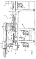
- a system 10 according to the present invention is bulk-fed with reels R from a wheel with radial blades, indicated generally by 12 in figs. 1 and 2. Any kind of loading tables or conveyor devices-not described, because already known--may be provided upstream of the wheel.
- a preferred wheel is a type shown in a previous European patent application EP-A-0113126 of the same applicant and comprises four or more radial blades. Each pair of blades defines a space for receiving a row of reels and transferring them into the system.
- Said system 10 is fed by a conveyor unit 14, usually a belt-type one, and comprises an orientation unit 16 and possibly a feeder-loader unit 18 (see fig. 8).
- the conveyor-belt unit may be of any known type and will not, therefore, be described in detail.
- the preferred kind is a dented belt 20 driven by a motor 21 and actuated by the presence of reels in the orientation unit 16.
- the orientation unit 16 comprises a first conveyor belt 22 and a second conveyor belt 24. In the exemplary embodiment both are shown assembled on the same fixed stand 26.
- the belt 22 runs on rollers 25, 25' driven by a motor 27.
- a slanting plate device 30, shown in figs. 1, 2 and 6 is fitted on a first section of belt 22.
- the - slanting plate device has a plate 31 which slides in guides 31a between an extended position and a retracted position.
- the first position it extends over one section of the belt from one side of the conveyor belt and has a slanting upper surface 32, a part of the slanting plate which is furthest away from the center line of the belt is higher and a part of the slanting plate which is nearest the center line is basically level with the belt.
- a particularly suitable angle of inclination is about 15° from the horizontal. It is preferable to provide that surface 32 be especially smooth and frictionless.
- the orientation unit 16 has a tilting unit 47, made up of a device 48 for detecting the position of the hole in the reels and a tilting device 50 operated by the detecting device, and cooperating therewith.
- the detecting device 48 comprises a system of photocells for indicating whether the through hole is vertical or horizontal in a stationary reel on the belt.
- the tilting device 50 comprises a frame 52 pivoted on a horizontal axis 54. Said frame 52 consists of two arms 54a and 54b, each one holding a jaw, 56a and 56b respectively. The two jaws can move towards and away from one another across the belt's longitudinal axis.
- Each jaw is attached to guide bars 57, which slide in guide sleeve 58, and is moved by a cylinder-piston 59.
- the frame 52 rotates for about 90° on the axis 54, as shown by the broken lines in fig. 2 in order to tilt the jaws 56a and 56b through 90°.
- the second conveyor belt 24 in the orientation unit has a "pen-type" end facing towards belt 22 is driven by a motor 62 and moves around rollers 60 and 61.
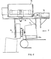
- a unit for rotating the reels is mounted on a fixed structure 66 at the side and above belt 24 and comprises a detecting device (not shown) and a pick-up device 68 with blades or a cradle. The latter is held by a bracket 72 connected to a vertical hub 74 (figs. 1 and 6).
- the hub is housed in a carriage 76 and is rotatable about its vertical axis 74, said carriage being able to traverse horizontally on a fixed structure 66, and being driven by a cylinder-piston unit 78, so that it can make a short and a long run, as will be explained in more detail below.
- the pick-up device comprises a pair of blades 68a and 68b, which rotate on parallel horizontal axes 70 between a spread apart position (shown by broken lines in fig. -7) and a closed position (shown by continuous lines in fig. 7).
- the blades' contact or seizing surfaces are arc-shaped in front view, as seen in fig. 7.
- the detecting device is for detecting whether a reel has its larger or smaller end facing forwards.
- Said device is of a known type (for example, as shown in the said preceding application EP-A-0113126 of the same applicant) and will not be described in detail.
- a loader-feeder unit 18 Downstream of unit 64, the system incfudes a loader-feeder unit 18.
- This comprises an inclined channel 80, which is preferably curved in plan view through an arc of about 90°. If the system is mainly for use with frusto-conical reels, the bottom of the channel may advantageously be shaped like a cylindrical-helical arc. Obviously, however, the plan shape and degree of inclination of the channel may differ according to the system's requirements.
- the initial section of channel 80 is arranged at a lower level than the surface of belt 24. In line with said initial section (fig. 9a), a wedge 82 can be inserted with a suitable surface for fitting the surface of a reel R.
- a movable abutment 84 can be fitted to the side of the channel, comprising a head 85 and a rod 86.
- the abutment can be moved transversally to the channel's axis between a position outside the channel and a position inside the channel, wherein the head of the abutment is facing a side of the channel at a distance therefrom.
- the channel comprises a mechanical gate 88, which can move transversally to the channel's axis between a position closing the channel and a position leaving it open.
- a piston-type pusher 90 is provided, having a transversal movement to the channel's axis; the pusher pushes each reel against a fixed stop 91 so as to stop the reel, and in this way it also stops the reels behind the first one.
- the channel 80 can be fitted with plate-type sides 93 and 94.
- Side 93 is pivoted at 95 and side 94 at 96, at opposite ends of the channel, whereas the ends of the plate-type sides opposite the pivoted ones each slide on a pin with a slot thereof, so that they can be adjusted in position and locked apart at the required dis- tarice.
- One of the longitudinal edges of each side protrudes into the channel in such a way, that a reel rolling along the channel is guided by contact with said edges alone.
- the system Downstream of channel 80 the system comprises a further channel or "bowl" 100, with a V-shaped bottom and axis transversal to said channel 80, and an openable door 102.
- a pusher 104 with a horizontal axis transversal to the axis of channel 80 is provided for pushing each reel R from the bowl towards holding means (of a per se known type) of a device downstream of the system.
- a control device (not shown) is provided above the pusher 104 for checking the size and attitude of each reel and for actuating the opening of door 102, in case the reel is not proper.
- the system is prearranged with the slanting plate device 30, the cradle device 68 above belt 24 and a wedge 82 with arc-shaped surface.
- the sides 93 and 94 are set in the widened position.
- the frusto-conical reels arrive on belt 22 in a random attitude, i.e. as shown in fig. 3 (in which they are drawn seen from above) and may have:
- the correct position, which is required in the bowl 100, is for example as in 3b, that is, with the reel lying along the belt's axis and its larger end facing forwards.
- the reels are fed onto belt 24 one by one, that is to say, a new reel can only be supplied to belt 22 for orienting when the preceding reel has left the belt. This can be achieved using known means, not shown.
- any reel in position 3e corrects it position so that the projection of its axis is parallel to the belt's axis, whereas plate 30 has no real effect on a reel in positions a, b, c and d in fig. 3.
- the reel is in one of the positions a, b, c or d in fig. 3.
- the reel is caught between jaws 56a and 56b and the hole-detecting device starts operating. If a vertical hole is detected (position 3c or 3d), the tilting of device 50 is actuated. Said device rotates the jaws holding the reel through 90° around the axis 54, then opens the jaws depositing the reel on belt 22 in an attitude lying along the axis and returns to the lowered position. On leaving device 50, the reel R, is positioned as in 3a or 3b and in this attitude it advances under device 68 which closes blades 68a and 68b and picks up the reel. The detecting device (not shown) of the rotating unit reads the position of the reel's ends.
- the cradle device 68 rotates through 180° around the vertical axis and deposits the reel in the channel 80 in position 3a. If the smaller end is already facing forwards in position 3a, device 68 moves forward and deposits the reel in channel 80.
- the control device checks the reel size and attitude and, if suitable, the reel is pushed by pusher 104 against a pick-up device. At this point reel R has its larger base facing forwards. Take note, however, that using the same system and process the reels can also be oriented in a different way than as described so far, that is, for example, with the smaller end facing forwards.
- the system is adjusted by arranging device 30 in the path, removing the detecting device of the rotation unit 64, removing abutment 84 from channel 80 and adjusting sides 93 and 94 to the size of the reel or cone.
- the cylindrical reels may arrive on belt 22 in any one of attitudes a, b and c, shown in fig. 4, that it so say, with their horizontal axis parallel to the belt's axis, or with their axis vertical, or with their axis lateral or oblique relative to the belt's axis. If the reel's axis is lateral or oblique, it is straightened by device 30 and, therefore, downstream of said device the reels can only be in attitude 4a or 4b. Then the reel is held between the jaws 56a and 56b of the tilting device 50 which, as explained in the case of a frusto-conical reel, tilts it through 90° according to whether or not a vertical hole is detected.
- the reel downstream of device 50 the reel can only be in attitude 4a. Then it is picked up in this attitude and deposited in channel 80, along which it rolls as far as pusher 90, gate 88 and bowl 100, in the same way as the frusto-conical reel.
- the system has the advantage of being easy to adjust for use with frusto-conical reels or cones or with cylindrical reels.
Landscapes
- Engineering & Computer Science (AREA)
- Mechanical Engineering (AREA)
- Replacing, Conveying, And Pick-Finding For Filamentary Materials (AREA)
- Specific Conveyance Elements (AREA)
- Preliminary Treatment Of Fibers (AREA)
- Attitude Control For Articles On Conveyors (AREA)
Claims (14)
Applications Claiming Priority (2)
| Application Number | Priority Date | Filing Date | Title |
|---|---|---|---|
| IT8421237A IT1209550B (it) | 1984-06-04 | 1984-06-04 | Impianto e procedimento per orientare in modo voluto corpi troncoconici e/o cilindrici forati, generalmente rocche di filato, alimentati alla rinfusa. |
| IT2123784 | 1984-06-04 |
Publications (2)
| Publication Number | Publication Date |
|---|---|
| EP0164648A1 EP0164648A1 (de) | 1985-12-18 |
| EP0164648B1 true EP0164648B1 (de) | 1988-02-24 |
Family
ID=11178839
Family Applications (1)
| Application Number | Title | Priority Date | Filing Date |
|---|---|---|---|
| EP85106598A Expired EP0164648B1 (de) | 1984-06-04 | 1985-05-29 | Vorrichtung und Verfahren zur Orientierung von durchgebohrten Stumpfkonen und/oder von zylindrischen Körpern, wie z.B. Garnspulen oder Konen in Masse angeliefert |
Country Status (6)
| Country | Link |
|---|---|
| US (1) | US4697690A (de) |
| EP (1) | EP0164648B1 (de) |
| JP (1) | JPS6118680A (de) |
| DE (1) | DE3561657D1 (de) |
| ES (1) | ES8607169A1 (de) |
| IT (1) | IT1209550B (de) |
Families Citing this family (2)
| Publication number | Priority date | Publication date | Assignee | Title |
|---|---|---|---|---|
| DE3909966A1 (de) * | 1989-03-28 | 1990-10-04 | Schlafhorst & Co W | Verfahren und anordnung zum kippen von kreuzspulen |
| US5605222A (en) * | 1996-04-24 | 1997-02-25 | Illinois Tool Works Inc. | Dual knife edge transfer conveyor |
Family Cites Families (15)
| Publication number | Priority date | Publication date | Assignee | Title |
|---|---|---|---|---|
| US2652140A (en) * | 1952-06-07 | 1953-09-15 | Sun Oil Co | Drum tumbler |
| FR1411937A (fr) * | 1964-09-01 | 1965-09-24 | Dispositif pour orienter des corps de filature ou objets analogues | |
| NL6503257A (de) * | 1965-03-15 | 1966-09-16 | ||
| US3361246A (en) * | 1966-09-01 | 1968-01-02 | Phillips Petroleum Co | Article aligning device |
| GB1179146A (en) * | 1967-11-01 | 1970-01-28 | Reynolds Metals Co | Orienting and Feeding Cores in a Coil-Winding Apparatus. |
| US3592326A (en) * | 1969-01-31 | 1971-07-13 | Ncr Co | Parcel post singulating and orienting apparatus |
| DE2201013A1 (de) * | 1972-01-11 | 1973-07-19 | Becker Klaus | Vorrichtung zum gleichrichten von textilspulen |
| JPS5443099B2 (de) * | 1973-06-22 | 1979-12-18 | ||
| SU460846A1 (ru) * | 1973-07-02 | 1975-02-25 | Ставропольский научно-исследовательский институт сельского хозяйства | Устройство дл ориентации изделий |
| US3924732A (en) * | 1973-11-19 | 1975-12-09 | Kartridg Pak Co | Apparatus for unscrambling and orienting overcaps |
| US4333558A (en) * | 1976-05-06 | 1982-06-08 | Shinko Electric Co., Ltd. | Photoelectric control system for parts orientation |
| IT8083474A0 (it) * | 1980-12-03 | 1980-12-03 | Savio Spa | Dispositivo di lubrificazione. |
| JPS58139979A (ja) * | 1982-02-16 | 1983-08-19 | Toyoda Autom Loom Works Ltd | コ−ンチ−ズの搬送方法および装置 |
| JPS58197323A (ja) * | 1982-05-12 | 1983-11-17 | Toyoda Autom Loom Works Ltd | 紡機における巻糸パツケ−ジの搬送方法 |
| IT1155099B (it) * | 1982-12-31 | 1987-01-21 | Raveggi Ornella Minnetti | Dispositivo tastatore-ribaltatore per disporre in un medesimo assetto corpi rastremati alimentati allineati con asseto casuale |
-
1984
- 1984-06-04 IT IT8421237A patent/IT1209550B/it active
-
1985
- 1985-05-29 DE DE8585106598T patent/DE3561657D1/de not_active Expired
- 1985-05-29 EP EP85106598A patent/EP0164648B1/de not_active Expired
- 1985-06-04 ES ES543889A patent/ES8607169A1/es not_active Expired
- 1985-06-04 JP JP60119872A patent/JPS6118680A/ja active Pending
- 1985-06-04 US US06/741,189 patent/US4697690A/en not_active Expired - Fee Related
Also Published As
| Publication number | Publication date |
|---|---|
| EP0164648A1 (de) | 1985-12-18 |
| ES8607169A1 (es) | 1986-06-01 |
| IT1209550B (it) | 1989-08-30 |
| DE3561657D1 (en) | 1988-03-31 |
| JPS6118680A (ja) | 1986-01-27 |
| US4697690A (en) | 1987-10-06 |
| IT8421237A0 (it) | 1984-06-04 |
| ES543889A0 (es) | 1986-06-01 |
Similar Documents
| Publication | Publication Date | Title |
|---|---|---|
| US5027700A (en) | Bundling and stacking machine | |
| US5056726A (en) | Yarn end loosening apparatus for a textile winding machine | |
| JPH05192068A (ja) | ガットキャタピラを分離させ且つ充填チューブ上に配置する方法及び装置 | |
| US5609237A (en) | Cylindrical object tipping device and method | |
| US4645058A (en) | Apparatus for orienting eggs in a egg handling systems | |
| NL1014057C2 (nl) | Graszodenverzamelaar. | |
| US4742967A (en) | System for delivering packages to an automatic winder | |
| EP0737769B1 (de) | Verfahren und Vorrichtung zur Handhabung einer Länge eines flexiblen Materials | |
| CA1175021A (en) | System for packaging ice-cream cones and like articles | |
| US4925000A (en) | Device for positioning bobbins with yarn packages | |
| US4697690A (en) | System and a process for orienting as required bored frusto-conical and/or cylindrical bodies, usually yarn reels or cones fed in bulk | |
| US5304030A (en) | Device for the automatic feeding of stacks of cutouts to a user machine | |
| JPH06316324A (ja) | 円錐形のチューブを整向するための装置 | |
| EP0113125A2 (de) | Anzeige-und Kippvorrichtung zum Gleichrichten von konischen Körpern willkürlich ausgerichtet geliefert | |
| US5772000A (en) | Hop vine transfer system | |
| US5746570A (en) | Apparatus for positioning a handle of a pail for a printing operation on the pail | |
| US5499708A (en) | Elongate member orienting ramp | |
| JP3506750B2 (ja) | 巻管装填装置 | |
| US5025911A (en) | Method and apparatus for tilting substantially rotationally symmetrical bodies such as cross-wound bobbins | |
| US3538990A (en) | Bobbin orienting installation | |
| US5911803A (en) | System and method for delivering elongate workpieces to a point of use | |
| US4234288A (en) | Apparatus for transporting elongated cylindrical workpieces | |
| JPH0617192B2 (ja) | 自動巻き取り機 | |
| JPH05270739A (ja) | キャディーにかぶせ嵌められた巻管を抜き取るための装置 | |
| JP3444833B2 (ja) | 山積み束からの棒材1本取出し装置 |
Legal Events
| Date | Code | Title | Description |
|---|---|---|---|
| PUAI | Public reference made under article 153(3) epc to a published international application that has entered the european phase |
Free format text: ORIGINAL CODE: 0009012 |
|
| AK | Designated contracting states |
Designated state(s): BE CH DE FR GB LI SE |
|
| 17P | Request for examination filed |
Effective date: 19851224 |
|
| 17Q | First examination report despatched |
Effective date: 19860917 |
|
| GRAA | (expected) grant |
Free format text: ORIGINAL CODE: 0009210 |
|
| AK | Designated contracting states |
Kind code of ref document: B1 Designated state(s): BE CH DE FR GB LI SE |
|
| PG25 | Lapsed in a contracting state [announced via postgrant information from national office to epo] |
Ref country code: CH Effective date: 19880224 Ref country code: LI Effective date: 19880224 |
|
| PG25 | Lapsed in a contracting state [announced via postgrant information from national office to epo] |
Ref country code: SE Effective date: 19880229 |
|
| REF | Corresponds to: |
Ref document number: 3561657 Country of ref document: DE Date of ref document: 19880331 |
|
| ET | Fr: translation filed | ||
| REG | Reference to a national code |
Ref country code: CH Ref legal event code: PL |
|
| PLBE | No opposition filed within time limit |
Free format text: ORIGINAL CODE: 0009261 |
|
| STAA | Information on the status of an ep patent application or granted ep patent |
Free format text: STATUS: NO OPPOSITION FILED WITHIN TIME LIMIT |
|
| 26N | No opposition filed | ||
| PGFP | Annual fee paid to national office [announced via postgrant information from national office to epo] |
Ref country code: FR Payment date: 19891107 Year of fee payment: 5 |
|
| PGFP | Annual fee paid to national office [announced via postgrant information from national office to epo] |
Ref country code: BE Payment date: 19891116 Year of fee payment: 5 |
|
| PGFP | Annual fee paid to national office [announced via postgrant information from national office to epo] |
Ref country code: GB Payment date: 19891130 Year of fee payment: 5 |
|
| PGFP | Annual fee paid to national office [announced via postgrant information from national office to epo] |
Ref country code: DE Payment date: 19891222 Year of fee payment: 5 |
|
| PG25 | Lapsed in a contracting state [announced via postgrant information from national office to epo] |
Ref country code: GB Effective date: 19900529 |
|
| PG25 | Lapsed in a contracting state [announced via postgrant information from national office to epo] |
Ref country code: BE Effective date: 19900531 |
|
| BERE | Be: lapsed |
Owner name: OFFICINE MINNETTI DI FEDERICO MINNETTI & C. S.A.S Effective date: 19900531 |
|
| GBPC | Gb: european patent ceased through non-payment of renewal fee | ||
| PG25 | Lapsed in a contracting state [announced via postgrant information from national office to epo] |
Ref country code: FR Effective date: 19910131 |
|
| PG25 | Lapsed in a contracting state [announced via postgrant information from national office to epo] |
Ref country code: DE Effective date: 19910201 |
|
| REG | Reference to a national code |
Ref country code: FR Ref legal event code: ST |