EP0164771A1 - Tube-image - Google Patents
Tube-image Download PDFInfo
- Publication number
- EP0164771A1 EP0164771A1 EP85200640A EP85200640A EP0164771A1 EP 0164771 A1 EP0164771 A1 EP 0164771A1 EP 85200640 A EP85200640 A EP 85200640A EP 85200640 A EP85200640 A EP 85200640A EP 0164771 A1 EP0164771 A1 EP 0164771A1
- Authority
- EP
- European Patent Office
- Prior art keywords
- deflection
- field
- electron beam
- plates
- display tube
- Prior art date
- Legal status (The legal status is an assumption and is not a legal conclusion. Google has not performed a legal analysis and makes no representation as to the accuracy of the status listed.)
- Granted
Links
Images

Classifications
-
- H—ELECTRICITY
- H01—ELECTRIC ELEMENTS
- H01J—ELECTRIC DISCHARGE TUBES OR DISCHARGE LAMPS
- H01J29/00—Details of cathode-ray tubes or of electron-beam tubes of the types covered by group H01J31/00
- H01J29/46—Arrangements of electrodes and associated parts for generating or controlling the ray or beam, e.g. electron-optical arrangement
- H01J29/48—Electron guns
- H01J29/51—Arrangements for controlling convergence of a plurality of beams by means of electric field only
-
- H—ELECTRICITY
- H01—ELECTRIC ELEMENTS
- H01J—ELECTRIC DISCHARGE TUBES OR DISCHARGE LAMPS
- H01J29/00—Details of cathode-ray tubes or of electron-beam tubes of the types covered by group H01J31/00
- H01J29/46—Arrangements of electrodes and associated parts for generating or controlling the ray or beam, e.g. electron-optical arrangement
- H01J29/70—Arrangements for deflecting ray or beam
- H01J29/701—Systems for correcting deviation or convergence of a plurality of beams by means of magnetic fields at least
- H01J29/707—Arrangements intimately associated with parts of the gun and co-operating with external magnetic excitation devices
Definitions
- the invention relates to an image display tube with an evacuated piston, which consists of an image window, a cone and a neck, in which an electron beam generator for generating an electron beam is accommodated, which is one on a screen attached to the inside of the image window Impact spot focused and deflected on this screen in two substantially perpendicular directions by deflection fields of a deflection coil system.
- Such a picture display tube is used, for example, in an arrangement for representing symbols and / or figures, e.g. generated by a computer.
- Such a picture display tube is known, for example, from the "Philips Data Handbook", Electron Tubes, Part 8, July 1983, Monitor Tubes.
- deflection coils are used in which the generated horizontal deflection field, but also mostly the vertical deflection field, is designed in a pillow-like manner to minimize the raster distortion.
- Such pillow-shaped deflection fields are known to influence the shape of the electron beam and thus, on the screen, the shape of the impact leak that this beam forms. It is now very desirable for data graphics tubes that the impact leak does not fluctuate too much across the entire screen, so that symbols and figures in the center, in the corners and on the edge of the screen are displayed almost equally sharply.
- field shapers to reduce deflection defocusing (see, for example, US Pat. No. 4,346,327).
- the invention has for its object to provide structurally simple and easy to arrange field formers for a picture display tube of the type mentioned.
- edge fields of the deflection fields on the electron beam generator side of the deflection coil system are made barrel-shaped by means of field formers which contain four plates of ferromagnetic material which are grouped around the electron beam and extend essentially from the electron beam in the deflection directions, and are attached to the beam generator end at a substantially equal distance from this beam generator end.
- the sometimes barrel-shaped distortion of the deflection fields means that the impact leakage distortion at the edge, but especially in the corners of the screen, is significantly reduced.
- the field formers can easily be cut from ferromagnetic sheet metal and attached to the centering plate at the end of the beam generator. It was also found that such field formers can increase the sensitivity of the deflection.
- the barrel-shaped distortion of the field becomes even clearer, but there is almost no increase in sensitivity to distraction.
- the field formers for the horizontal deflection field preferably extend from the beam generator over a greater distance along the electron beam than the field formers for the vertical deflection field. This is particularly the case with so-called “hybrid” deflection coils (deflection coils both with saddle and with toroid coils).
- the plates extending from the electron beam in the deflection directions are preferably provided with gaps extending in the deflection directions to prevent eddy currents in the field formers.
- the additional plates made of ferromagnetic material can also be provided with slots. These slots are particularly important in field formers or in parts of field formers that extend essentially perpendicular to the horizontal field, because this deflection field fluctuates with the highest frequencies; (Horizontal frequency).
- Fig. 1 is a partially broken, pers perspective view of an image display tube according to the invention.
- This tube contains a glass bulb 1, which consists of an image window 2, a cone 3 and a neck 4, in which an electron beam generator 5 for generating an electron beam 6 is received.
- This electron beam 6 is focused on a screen 7 to an impact spot 8.
- the screen 7 is attached to the inside of the picture window 2.
- the electron beam is deflected 'via the screen 7 in two directions x and y which are perpendicular to one another with the aid of the deflection coil system 9.
- the deflection fields are designed in a pillow shape.
- the deflection defocusing caused thereby can be reduced with field shapers according to FIG. 2.
- These field formers are attached to the end 10 of the beam generator 5 which faces the deflection coil system 9.
- the display tube is equipped with a base 11 with connection pins 12.
- FIG. 2 is a perspective view of the beam generator 5 of the display tube of Figure 1.
- This beam generator includes a control grating (G-1) 20, a second grating (G-2) 21 and a focusing lens made up of electrodes 22, 23 and 24 exists (G-3, G-4 or G-5).
- the cathode which is not visible here, is located in the control grid.
- the voltages to the electrodes are shown in the figure.
- a centering plate 26 provided with an opening 25 is attached to the electrode 24. Centering springs are attached to this plate for centering the jet generator in the tube neck, but are omitted in this figure.
- the edge field of the pillow-shaped deflection fields of the deflection coil system 9 see FIG.
- the field formers 28 and 30 are provided in the field formers 28 and 30 running perpendicular to the horizontal field. It is of course possible also to provide the field formers 27 and 29 with such slots.
- the field formers have, for example, a length of 10 mm in the direction of the electron gun axis 32; its width is, for example, 4.8 mm and the thickness is 0.25 mm.
- the field formers can be cut from NiFe sheet (with 48% Ni) and attached to the centering plate 26 by means of spot welding.
- dx and dy are the impact leak dimensions in mm in the center of the screen, on the top and bottom (N / S), on the left and right side (E / W) and in the corners of the screen.
- the average magnification of the impact leak dimensions (in%), in particular in the corners of the screen, is significantly reduced.
- the impingement leak dimensions apply to an electron beam current of approximately 100 / uA in a picture display tube with a picture diagonal of 31 cm and a 90 ° deflection of the electron beam.
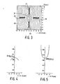
- FIG. 3 shows the barrel-shaped distortion of a pillow-shaped horizontal deflection field, of which some field lines 40 of the field formers 27, 28, 29 and 30 are shown.
- FIG. 5 shows the magnetic field strength B, divided by the supplied field strength B ext , as a percentage depending on the distance from the axis 32 of the beam generator 5 in the direction of the field 40 according to FIG. 3.
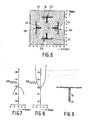
- FIG. 6 shows the barrel distortion of a pillow-shaped horizontal deflection field, of which some field lines 50 are shown, by T-shaped field formers 127, 128, 129, 130.
- T-shaped field formers 127, 128, 129, 130 At the ends 51 of the plates facing away from the electron beam 6, which extend away from the electron beam, additional plates 52 and 53 made of ferromagnetic material are attached, which extend essentially perpendicular to the field to be formed.
- the plates 52 extend almost perpendicular to the horizontal field shown and the plates 53 almost perpendicular to the vertical field, not shown.
- FIGS. 7 and 8 are analogous to FIGS. 4 and 5.
- the standardized field strength is approximately 100%.
- the field is designed with the field formers according to FIG. 3 with a clear barrel shape. There is no increase in sensitivity to distraction.
- FIG. 9 shows a cross section through a T-shaped field former 60, which consists of a piece of sheet metal is made.
- the radius of curvature of the end 61 should be chosen to be as small as possible for the best possible barrel-shaped field.
Landscapes
- Vessels, Lead-In Wires, Accessory Apparatuses For Cathode-Ray Tubes (AREA)
- Video Image Reproduction Devices For Color Tv Systems (AREA)
- Image-Pickup Tubes, Image-Amplification Tubes, And Storage Tubes (AREA)
- Details Of Television Scanning (AREA)
Applications Claiming Priority (2)
| Application Number | Priority Date | Filing Date | Title |
|---|---|---|---|
| NL8401444A NL8401444A (nl) | 1984-05-07 | 1984-05-07 | Beeldbuis. |
| NL8401444 | 1984-05-07 |
Publications (2)
| Publication Number | Publication Date |
|---|---|
| EP0164771A1 true EP0164771A1 (fr) | 1985-12-18 |
| EP0164771B1 EP0164771B1 (fr) | 1989-07-12 |
Family
ID=19843907
Family Applications (1)
| Application Number | Title | Priority Date | Filing Date |
|---|---|---|---|
| EP85200640A Expired EP0164771B1 (fr) | 1984-05-07 | 1985-04-24 | Tube-image |
Country Status (9)
| Country | Link |
|---|---|
| US (1) | US4691139A (fr) |
| EP (1) | EP0164771B1 (fr) |
| JP (1) | JPS60241630A (fr) |
| KR (1) | KR920001871B1 (fr) |
| CA (1) | CA1239975A (fr) |
| DD (1) | DD233454A5 (fr) |
| DE (1) | DE3571529D1 (fr) |
| ES (1) | ES8700498A1 (fr) |
| NL (1) | NL8401444A (fr) |
Cited By (1)
| Publication number | Priority date | Publication date | Assignee | Title |
|---|---|---|---|---|
| FR2818799A1 (fr) * | 2000-12-22 | 2002-06-28 | Thomson Tubes & Displays | Systeme de deflexion pour tube a rayons cathodiques couleur corrige en coma horizontale |
Citations (4)
| Publication number | Priority date | Publication date | Assignee | Title |
|---|---|---|---|---|
| US3866080A (en) * | 1973-08-08 | 1975-02-11 | Rca Corp | Inline electron gun having magnetically permeable plates for enhancing convergence of electron beams |
| US4057747A (en) * | 1974-10-14 | 1977-11-08 | Tokyo Shibaura Electric Company, Ltd. | In-line plural beam color cathode ray tube having deflection defocus correcting elements |
| US4346327A (en) * | 1978-02-27 | 1982-08-24 | U.S. Philips Corporation | Display tube for displaying color pictures |
| EP0112567A1 (fr) * | 1982-12-24 | 1984-07-04 | Matsushita Electronics Corporation | Tube à rayon cathodique à rayon unique |
Family Cites Families (6)
| Publication number | Priority date | Publication date | Assignee | Title |
|---|---|---|---|---|
| JPS5522907B2 (fr) * | 1973-05-04 | 1980-06-19 | ||
| JPS52123831A (en) * | 1976-04-12 | 1977-10-18 | Toshiba Corp | Cothode ray tube |
| JPS5583136A (en) * | 1978-12-19 | 1980-06-23 | Matsushita Electronics Corp | Color image pick-up tube |
| JPS5738544A (en) * | 1980-08-19 | 1982-03-03 | Matsushita Electronics Corp | Electromagnetic deflection system picture tube system equipment |
| JPS5761246A (en) * | 1980-09-30 | 1982-04-13 | Mitsubishi Electric Corp | Electron gun for color picture tube |
| JPS5859536A (ja) * | 1981-10-06 | 1983-04-08 | Toshiba Corp | カラ−受像管 |
-
1984
- 1984-05-07 NL NL8401444A patent/NL8401444A/nl not_active Application Discontinuation
- 1984-07-05 US US06/627,948 patent/US4691139A/en not_active Expired - Fee Related
-
1985
- 1985-04-24 DE DE8585200640T patent/DE3571529D1/de not_active Expired
- 1985-04-24 EP EP85200640A patent/EP0164771B1/fr not_active Expired
- 1985-05-02 CA CA000480636A patent/CA1239975A/fr not_active Expired
- 1985-05-03 ES ES542824A patent/ES8700498A1/es not_active Expired
- 1985-05-03 KR KR1019850003019A patent/KR920001871B1/ko not_active Expired
- 1985-05-03 DD DD85275962A patent/DD233454A5/de unknown
- 1985-05-04 JP JP60095864A patent/JPS60241630A/ja active Pending
Patent Citations (4)
| Publication number | Priority date | Publication date | Assignee | Title |
|---|---|---|---|---|
| US3866080A (en) * | 1973-08-08 | 1975-02-11 | Rca Corp | Inline electron gun having magnetically permeable plates for enhancing convergence of electron beams |
| US4057747A (en) * | 1974-10-14 | 1977-11-08 | Tokyo Shibaura Electric Company, Ltd. | In-line plural beam color cathode ray tube having deflection defocus correcting elements |
| US4346327A (en) * | 1978-02-27 | 1982-08-24 | U.S. Philips Corporation | Display tube for displaying color pictures |
| EP0112567A1 (fr) * | 1982-12-24 | 1984-07-04 | Matsushita Electronics Corporation | Tube à rayon cathodique à rayon unique |
Cited By (2)
| Publication number | Priority date | Publication date | Assignee | Title |
|---|---|---|---|---|
| FR2818799A1 (fr) * | 2000-12-22 | 2002-06-28 | Thomson Tubes & Displays | Systeme de deflexion pour tube a rayons cathodiques couleur corrige en coma horizontale |
| WO2002052606A1 (fr) * | 2000-12-22 | 2002-07-04 | Thomson Licensing S.A. | Systeme de deflexion pour tube cathodique couleur avec correction horizontale du coma |
Also Published As
| Publication number | Publication date |
|---|---|
| DE3571529D1 (en) | 1989-08-17 |
| CA1239975A (fr) | 1988-08-02 |
| JPS60241630A (ja) | 1985-11-30 |
| DD233454A5 (de) | 1986-02-26 |
| ES542824A0 (es) | 1986-10-01 |
| KR850008555A (ko) | 1985-12-18 |
| NL8401444A (nl) | 1985-12-02 |
| KR920001871B1 (ko) | 1992-03-06 |
| ES8700498A1 (es) | 1986-10-01 |
| US4691139A (en) | 1987-09-01 |
| EP0164771B1 (fr) | 1989-07-12 |
Similar Documents
| Publication | Publication Date | Title |
|---|---|---|
| DE2608463C3 (de) | Inline-Farbbildröhre | |
| DE69020478T2 (de) | Farbbildröhrensystem mit reduziertem Fleckwachstum. | |
| DE2223818C3 (de) | Selbstkonvergierende Farbbildwiedergabeeinrichtung | |
| AT391380B (de) | Selbstkonvergierendes ablenkjoch | |
| DE69210943T2 (de) | Bildröhrenablenkeinheit mit Vertikalablenkspulen vom Semi-Satteltyp | |
| DE2224404C3 (de) | Vorrichtung zum Beseitigen der horizontalen Unsymmetrie der Raster in einer Farbkathodenstrahlröhre | |
| DE2545718A1 (de) | Kathodenstrahl-farbbildroehre | |
| DE2544294B2 (de) | Farbbildsichtgeraet | |
| DE2907192C2 (de) | Farbbildröhre mit Inline-Elktronenstrahlerzeugungssystem | |
| DD259059A5 (de) | Farbbild-wiedergabesystem | |
| DE69013183T2 (de) | Farbbildröhrensystem mit reduziertem Fleckwachstum. | |
| DE69510968T2 (de) | Farbkathodenstrahlröhre | |
| DE3417392C2 (de) | Fernsehbild-Wiedergabegerät | |
| DE2004880B2 (de) | Elektrostatische elektronenlinse fuer elektronenstrahlbildroehren zum fokussieren und konvergieren mehrerer elektronenstrahlbuendel und deren verwendung | |
| DE2917268C2 (fr) | ||
| DE69517377T2 (de) | Ablenkjoch und mit dem Ablenkjoch versehene Farbkathodenstrahlröhre | |
| DD238473A5 (de) | Schlitzmaskenelektronenkanone fuer katodenstrahlroehren | |
| DE3121457A1 (de) | "einrichtung zur verstaerkung der ablenkung bei einer bildroehre" | |
| DE3844731C2 (fr) | ||
| DE3106846A1 (de) | Kompensierte ablenkeinrichtung fuer einen fernsehempfaenger mit inline-bildroehre | |
| EP0164771B1 (fr) | Tube-image | |
| DE3402857A1 (de) | Farbbildroehre mit inline-elektronenstrahlerzeugungssystem | |
| EP0138264B1 (fr) | Tube-image couleurs | |
| DE69704978T2 (de) | Kompensierungsvorrichtung für Kathodenstrahlröhre-Rasterverzerrungen | |
| DE3216039C2 (de) | Elektronenstrahl-Erzeugungssystem einer Kathodenstrahlröhre |
Legal Events
| Date | Code | Title | Description |
|---|---|---|---|
| PUAI | Public reference made under article 153(3) epc to a published international application that has entered the european phase |
Free format text: ORIGINAL CODE: 0009012 |
|
| AK | Designated contracting states |
Designated state(s): DE FR GB IT |
|
| 17P | Request for examination filed |
Effective date: 19860603 |
|
| 17Q | First examination report despatched |
Effective date: 19871228 |
|
| GRAA | (expected) grant |
Free format text: ORIGINAL CODE: 0009210 |
|
| AK | Designated contracting states |
Kind code of ref document: B1 Designated state(s): DE FR GB IT |
|
| REF | Corresponds to: |
Ref document number: 3571529 Country of ref document: DE Date of ref document: 19890817 |
|
| ITF | It: translation for a ep patent filed | ||
| GBT | Gb: translation of ep patent filed (gb section 77(6)(a)/1977) | ||
| ET | Fr: translation filed | ||
| PLBE | No opposition filed within time limit |
Free format text: ORIGINAL CODE: 0009261 |
|
| STAA | Information on the status of an ep patent application or granted ep patent |
Free format text: STATUS: NO OPPOSITION FILED WITHIN TIME LIMIT |
|
| 26N | No opposition filed | ||
| ITTA | It: last paid annual fee | ||
| ITPR | It: changes in ownership of a european patent |
Owner name: CAMBIO RAGIONE SOCIALE;PHILIPS ELECTRONICS N.V. |
|
| REG | Reference to a national code |
Ref country code: FR Ref legal event code: CD |
|
| PGFP | Annual fee paid to national office [announced via postgrant information from national office to epo] |
Ref country code: GB Payment date: 19960329 Year of fee payment: 12 |
|
| PGFP | Annual fee paid to national office [announced via postgrant information from national office to epo] |
Ref country code: FR Payment date: 19960429 Year of fee payment: 12 |
|
| PGFP | Annual fee paid to national office [announced via postgrant information from national office to epo] |
Ref country code: DE Payment date: 19960625 Year of fee payment: 12 |
|
| PG25 | Lapsed in a contracting state [announced via postgrant information from national office to epo] |
Ref country code: GB Effective date: 19970424 |
|
| GBPC | Gb: european patent ceased through non-payment of renewal fee |
Effective date: 19970424 |
|
| PG25 | Lapsed in a contracting state [announced via postgrant information from national office to epo] |
Ref country code: FR Free format text: LAPSE BECAUSE OF NON-PAYMENT OF DUE FEES Effective date: 19971231 |
|
| PG25 | Lapsed in a contracting state [announced via postgrant information from national office to epo] |
Ref country code: DE Free format text: LAPSE BECAUSE OF NON-PAYMENT OF DUE FEES Effective date: 19980101 |
|
| REG | Reference to a national code |
Ref country code: FR Ref legal event code: ST |