EP0164801B1 - Appareil à résonance de spin nucléaire avec un élément de réglage pour l'adaptation ou l'accord du résonateur - Google Patents
Appareil à résonance de spin nucléaire avec un élément de réglage pour l'adaptation ou l'accord du résonateur Download PDFInfo
- Publication number
- EP0164801B1 EP0164801B1 EP85200887A EP85200887A EP0164801B1 EP 0164801 B1 EP0164801 B1 EP 0164801B1 EP 85200887 A EP85200887 A EP 85200887A EP 85200887 A EP85200887 A EP 85200887A EP 0164801 B1 EP0164801 B1 EP 0164801B1
- Authority
- EP
- European Patent Office
- Prior art keywords
- coil
- magnetic field
- movement
- resonator
- adjusting
- Prior art date
- Legal status (The legal status is an assumption and is not a legal conclusion. Google has not performed a legal analysis and makes no representation as to the accuracy of the status listed.)
- Expired
Links
Images


Classifications
-
- G—PHYSICS
- G01—MEASURING; TESTING
- G01R—MEASURING ELECTRIC VARIABLES; MEASURING MAGNETIC VARIABLES
- G01R33/00—Arrangements or instruments for measuring magnetic variables
- G01R33/20—Arrangements or instruments for measuring magnetic variables involving magnetic resonance
- G01R33/28—Details of apparatus provided for in groups G01R33/44 - G01R33/64
- G01R33/32—Excitation or detection systems, e.g. using radio frequency signals
- G01R33/36—Electrical details, e.g. matching or coupling of the coil to the receiver
- G01R33/3628—Tuning/matching of the transmit/receive coil
-
- G—PHYSICS
- G01—MEASURING; TESTING
- G01R—MEASURING ELECTRIC VARIABLES; MEASURING MAGNETIC VARIABLES
- G01R33/00—Arrangements or instruments for measuring magnetic variables
- G01R33/20—Arrangements or instruments for measuring magnetic variables involving magnetic resonance
- G01R33/28—Details of apparatus provided for in groups G01R33/44 - G01R33/64
Definitions
- the invention relates to a nuclear magnetic resonance device with a magnet for generating a homogeneous static main magnetic field and a resonant arrangement for generating a high-frequency magnetic field which is at least approximately perpendicular to the main magnetic field, with at least one actuator which is connected to an actuator for adapting the resonator to a high-frequency generator and / or Tuning the resonator acts.
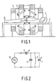
- a magnetic resonance imaging device of this type is shown in FIG. 1. It comprises an electromagnet consisting of four coils, which generates a static, homogeneous magnetic field running in the direction of the common horizontal coil axis.
- a patient 3 mounted on a table top 2 inside the electromagnet is enclosed by a high-frequency coil 4, which generates a high-frequency magnetic field in pulses that is directed perpendicular to the main magnetic field generated by the electromagnet.
- the frequency of the high-frequency magnetic field is proportional to the flux density of the main magnetic field, which, depending on the design of the electromagnet, can be between 0.1 T and 2 T; the proportionality constant is equal to the gyromagnetic ratio.
- Nuclear magnetic resonances can therefore be generated within the volume enclosed by the high-frequency coil.
- four so-called gradient coils 5, which generate a magnetic field that runs in the direction of the main magnetic field and changes linearly in this direction ensure that this excitation is limited to a vertical layer 6.
- the frequency of the vibrations generated by the high-frequency coil corresponds exactly to the nuclear magnetic resonance frequency specified by the gyromagnetic ratio and the flux density of the main magnetic field, and that the resonator containing the high-frequency coil 4 is always adapted to the high-frequency generator supplying the high-frequency vibrations.
- the resonance frequency is detuned and the quality is reduced, depending on body size and body area. of the resonator. This effect is caused by the dielectric properties and the electrical conductivity of the body tissue.
- the high-frequency generator or the high-frequency receiver which is then connected to the resonator and receives the nuclear magnetic resonance signal that arises in the examined body area, is no longer adapted to the resonator at the so-called nuclear magnetic resonance frequency.
- the resonator comprises the coil 5 as well as the capacitor 9 and the rotary capacitor 7, which are connected in parallel with the coil 5.
- the capacitor 9 can also be omitted if the dimensions are suitable.
- This resonator is connected to a high-frequency generator 10 via a rotary capacitor 8. The adjustment takes place with the help of the variable capacitor 8 and the adjustment with the help of the variable capacitor 7, the two processes influencing one another.
- variable capacitors are difficult. These are arranged outside the high-frequency coil inside the electromagnet and cannot be adjusted by stepper motors or the like, because their ferromagnetic parts would disturb the homogeneity of the magnetic field.
- the stepper motors must therefore be arranged outside the electromagnet at such a distance that they do not interfere with the homogeneity of the main magnetic field and are not impaired in their function by the stray fields of the electromagnet, and they must be coupled to the actuators arranged inside the electromagnet via long drive rods .
- the actuator contains a coil which is exposed to the main magnetic field and is movably mounted, that the coil is connected to a current pulse generator for generating current pulses of one or the other polarity, through which the coil in one or the other direction from its rest position is deflected, and that the deflection movement is transmitted to the actuator via a step mechanism that converts the reciprocating movement of the coil into a stepwise movement of the actuator, the direction of which is uniquely assigned to the direction of the deflection.
- the coil When a current impulse flows through it, the coil is deflected from its rest position in the main magnetic field and returns after the current impulse - e.g. B. with the help of return springs - back to their rest position. If several current pulses of the same polarity are fed to the coil, this therefore executes a reciprocating movement. This is done with the help of Stepping mechanism implemented in a step (rotary or push) movement of the actuator, the direction of which is uniquely assigned to the direction of the deflection and thus the polarity of the current pulses.
- Stepping mechanism implemented in a step (rotary or push) movement of the actuator, the direction of which is uniquely assigned to the direction of the deflection and thus the polarity of the current pulses.
- Such an actuator does not require ferromagnetic parts. For this reason and because the lines from the current pulse generator to the coil can remain currentless during the actual measurement, such an actuator does not impair the field homogeneity.
- an elongated solenoid coil 11 is connected to a mounting body 12 which is mounted in a housing frame 13 at its lower end so as to be pivotable about a horizontal axis 14.
- the upper end of the holder body 12 is connected to a control member 15 such that a tilting movement of the bobbin 12 is converted into a pushing movement of the control member 15, which is guided in a horizontally extending guide rail 16.
- Two springs attached to both ends of the control member 15 cause the bracket body and with it the solenoid coil to be at rest, i.e. if no other external forces are acting on them, assume a vertical position.
- the coil axis then runs perpendicular to the main magnetic field, the direction of which is indicated in FIG. 3 by the horizontally extending arrows 18.
- a current pulse generator 19 is connected to the connections of the coil 11, e.g. can contain a direct current source which can be connected to the connections via a controllable multi-pole changeover switch such that either current in one direction, no current or current in the opposite direction can flow through the coil 11.
- control member 12 executes a movement from the center to the left (or to the right) and backward movement.
- This reciprocating movement is converted by the step mechanism into a step-wise rotary movement of the rotor of the variable capacitor 7 or 8, so that its polarity increases gradually with current pulses of one polarity and gradually decreases with current pulses of the other polarity.
- the control member 15 is provided with two pawls 21 and 22, which are arranged symmetrically to the central position of the control member 15 and are pivotally mounted about vertical journals 23 and 24, respectively.
- Springs, not shown, ensure that the ends of the control pawls facing away from each other are pressed against two ratchet gears 25 and 26, which are offset from one another in the direction of the magnetic field and are rotatably mounted about a vertical axis symmetrically to the rest position of the control member 15.
- the other control pawl 22 is pressed by this movement of the control member 15 against the control pin 27, which control pawl simultaneously executes a counterclockwise pivoting movement about the bearing pin 24 due to the banana-shaped curvature of the outer contour facing the control pin 27, whereby the other end of the control pawl 22 causes the pawl gear 26 releases.
- the step movement of the ratchet gear 25 is transmitted via a gear wheel 28, which is fixedly connected to the ratchet gear 25 and rotatable about the same axis as this, to a gear wheel 30, which is connected to the rotor of the variable capacitor 7 or 8 (FIG. 3 ).
- the gear 30 is in engagement with a gear 29 which is connected to the ratchet gear 26 in the same way as the gear 28 with the ratchet gear 25.
- a toothed rack 31, indicated by dashed lines in FIG. 4 can be used, which meshes with the gearwheels 28 and 29 and is connected to a dielectric which - As known from DE-OS 3 347 597 - is shifted inside a coaxial line acting as a stub line, so that its reactance changes step by step.
- the translatory, back and forth movement of the control member 15 is thus converted into a gradual pushing movement of the rack 31.
- FIGS. 5 and 6 An embodiment is shown in FIGS. 5 and 6 in which the pivoting movement of the coil is implemented directly and not via a detour of a translatory movement.
- the coil which comprises one or more turns with, for example, a rectangular cross section, is rotatably mounted about its axis of symmetry 33 running perpendicular to the main magnetic field and is arranged in the rest position such that the magnetic field lines of the main magnetic field run parallel to the coil plane.
- a driver lever 34 With the upper end of the coil, a driver lever 34 is fixedly connected, which is provided near its end with driver pins 35 which engage around one arm of a three-armature armature 36, the other two arms of which are provided with pawls 37, each of which with a gear 38 can engage.
- the armature 36 is rotatably fastened to a further lever 40 about an axis 39 parallel to the axis of rotation of the coil 32 and its two arms carrying the pawls 37 are connected to this lever via springs so that they are symmetrical to this lever in the rest position.
- the lever 40 itself is in turn held in a rest position by springs 41.
- the lever 34 or the coil 32, the gear 38 and the further lever 40 are rotatably supported about the same axis independently of one another.
- the invention thus uses the forces exerted by the main magnetic field on a current-carrying coil to generate an adjustment of the actuator.
- the actuator according to the invention only contains non-magnetic material, and after the adaptation or retuning, no more current flows through the coil, so that no interference fields can arise in the subsequent nuclear magnetic resonance measurements, which could influence the homogeneity of the main magnetic field.
- This actuator which is structurally combined with the high-frequency coil 4 (FIG. 1) and can be exchanged with it for another high-frequency coil with a corresponding actuator, is very well suited for automatic adaptation or retuning with the aid of a computer, because only current pulses are used to drive it the required number must be generated.
Landscapes
- Physics & Mathematics (AREA)
- Condensed Matter Physics & Semiconductors (AREA)
- General Physics & Mathematics (AREA)
- Magnetic Resonance Imaging Apparatus (AREA)
Claims (4)
Applications Claiming Priority (2)
| Application Number | Priority Date | Filing Date | Title |
|---|---|---|---|
| DE3421830 | 1984-06-13 | ||
| DE19843421830 DE3421830A1 (de) | 1984-06-13 | 1984-06-13 | Kernspinresonanzgeraet mit einem stellglied zur anpassung oder zum nachstimmen des resonators |
Publications (3)
| Publication Number | Publication Date |
|---|---|
| EP0164801A2 EP0164801A2 (fr) | 1985-12-18 |
| EP0164801A3 EP0164801A3 (en) | 1987-05-27 |
| EP0164801B1 true EP0164801B1 (fr) | 1989-11-29 |
Family
ID=6238198
Family Applications (1)
| Application Number | Title | Priority Date | Filing Date |
|---|---|---|---|
| EP85200887A Expired EP0164801B1 (fr) | 1984-06-13 | 1985-06-06 | Appareil à résonance de spin nucléaire avec un élément de réglage pour l'adaptation ou l'accord du résonateur |
Country Status (4)
| Country | Link |
|---|---|
| US (1) | US4698595A (fr) |
| EP (1) | EP0164801B1 (fr) |
| JP (1) | JPS6111644A (fr) |
| DE (2) | DE3421830A1 (fr) |
Families Citing this family (18)
| Publication number | Priority date | Publication date | Assignee | Title |
|---|---|---|---|---|
| US4920318A (en) * | 1985-08-14 | 1990-04-24 | Picker International, Inc. | Surface coil system for magnetic resonance imaging |
| JPH0628648B2 (ja) * | 1985-09-10 | 1994-04-20 | 株式会社東芝 | コイルシステム |
| US4950993A (en) * | 1985-11-29 | 1990-08-21 | Thomson-Cgr | Device and method for adjusting a radiofrequency antenna of a nuclear magnetic resonance apparatus |
| US4733190A (en) * | 1987-03-16 | 1988-03-22 | Medical Advances, Inc. | NMR local coil with adjustable spacing |
| JPH0616076B2 (ja) * | 1987-07-27 | 1994-03-02 | 株式会社東芝 | 磁気共鳴イメージング装置 |
| JP2538954B2 (ja) * | 1987-11-18 | 1996-10-02 | 株式会社東芝 | 磁気共鳴診断装置 |
| JPH01131651A (ja) * | 1987-11-18 | 1989-05-24 | Toshiba Corp | 磁気共鳴診断装置 |
| EP0385367B1 (fr) * | 1989-02-27 | 1995-10-25 | Medrad Inc. | Sonde intracavitaire et dispositif d'interface pour l'imagerie par résonance magnétique et spectroscopie |
| DE4119674A1 (de) * | 1991-06-14 | 1992-12-17 | Spectrospin Ag | Stellantrieb |
| US5483163A (en) * | 1993-08-12 | 1996-01-09 | The United States Of America As Represented By The Department Of Health And Human Services | MRI coil using inductively coupled individually tuned elements arranged as free-pivoting components |
| US5672172A (en) * | 1994-06-23 | 1997-09-30 | Vros Corporation | Surgical instrument with ultrasound pulse generator |
| DE4424843C1 (de) * | 1994-07-14 | 1996-02-01 | Spectrospin Ag | Mischvorrichtung und Verfahren zum Durchmischen von Fluiden in einer Hochdruck-NMR-Meßeinrichtung |
| DE4442742C1 (de) * | 1994-12-01 | 1996-05-23 | Bruker Analytische Messtechnik | Probenkopf für die Kernresonanz-Spektroskopie |
| DE19744763C2 (de) * | 1997-10-10 | 1999-09-02 | Bruker Ag | NMR-Probenkopf mit integrierter Fernabstimmung |
| US6083166A (en) * | 1997-12-02 | 2000-07-04 | Situs Corporation | Method and apparatus for determining a measure of tissue manipulation |
| US6217518B1 (en) | 1998-10-01 | 2001-04-17 | Situs Corporation | Medical instrument sheath comprising a flexible ultrasound transducer |
| WO2006107344A2 (fr) | 2004-11-15 | 2006-10-12 | Medrad, Inc. | Sondes intracavitaires et interfaces associees utilisees pour obtenir des images et des spectres de structures intracavitaires au moyen de systemes de resonance magnetique de haute resolution |
| JP4437073B2 (ja) | 2002-05-16 | 2010-03-24 | メドラッド インコーポレーテッド | 3.0テスラの磁気共鳴システムを使用して腔内構造の画像及びスペクトルを得るためのシステム及び方法 |
Family Cites Families (8)
| Publication number | Priority date | Publication date | Assignee | Title |
|---|---|---|---|---|
| US1875329A (en) * | 1932-09-06 | Henbi chibeix | ||
| US3447047A (en) * | 1968-03-20 | 1969-05-27 | Wesley Newton Lindsay | Motor driven variable capacitor |
| DE2409947A1 (de) * | 1974-03-01 | 1975-09-11 | Sp K Bjuro I Radiotechniki I E | Meterwellen-impulsradiospektrometer zur kernquadrupolresonanz-untersuchung fester proben |
| US4095168A (en) * | 1977-02-22 | 1978-06-13 | Varian Associates, Inc. | Rf pick-up coil circuit for a wide tuning range nuclear magnetic resonance probe |
| US4312025A (en) * | 1978-12-06 | 1982-01-19 | Rca Corporation | Magnetic variable capacitor |
| SU894506A1 (ru) * | 1980-05-16 | 1981-12-30 | Институт физики им. Л.В.Киренского СО АН СССР | Датчик сигнала магнитного резонанса |
| JPS59155239A (ja) * | 1983-02-23 | 1984-09-04 | 株式会社東芝 | 診断用核磁気共鳴装置 |
| DE3336254A1 (de) * | 1983-10-05 | 1985-04-25 | Siemens AG, 1000 Berlin und 8000 München | Geraet zur erzeugung von bildern eines untersuchungsobjektes |
-
1984
- 1984-06-13 DE DE19843421830 patent/DE3421830A1/de not_active Withdrawn
-
1985
- 1985-05-17 US US06/735,006 patent/US4698595A/en not_active Expired - Fee Related
- 1985-06-06 DE DE8585200887T patent/DE3574500D1/de not_active Expired - Lifetime
- 1985-06-06 EP EP85200887A patent/EP0164801B1/fr not_active Expired
- 1985-06-11 JP JP60125262A patent/JPS6111644A/ja active Pending
Also Published As
| Publication number | Publication date |
|---|---|
| DE3574500D1 (de) | 1990-01-04 |
| US4698595A (en) | 1987-10-06 |
| JPS6111644A (ja) | 1986-01-20 |
| EP0164801A3 (en) | 1987-05-27 |
| DE3421830A1 (de) | 1985-12-19 |
| EP0164801A2 (fr) | 1985-12-18 |
Similar Documents
| Publication | Publication Date | Title |
|---|---|---|
| EP0164801A2 (fr) | Appareil à résonance de spin nucléaire avec un élément de réglage pour l'adaptation ou l'accord du résonateur | |
| DE3323657C2 (de) | Einstellbare HF-Spulenanordnung | |
| EP0223284B1 (fr) | Arrangement de bobines haute-fréquence pour appareil pour la résonance de spin nucléaire | |
| EP0930509B1 (fr) | Appareil de résonance magnétique avec un instrument médical et procédé pour déterminer la position de l'instrument médical | |
| EP0186238B1 (fr) | Procédé de production d'un signal de déplacement et tomographe de spins nucléaires pour un tel procédé | |
| DE4002160C2 (fr) | ||
| EP0136642B1 (fr) | Appareil de production d'images d'un objet examiné | |
| EP0361190A1 (fr) | Dispositif de bobines de surface pour examens par résonance magnétique nucléaire | |
| DE2917794C2 (de) | Bimodaler Resonator für Elektronenspinresonanz-Experimente | |
| DE4223909C2 (de) | Vorrichtungen zum Messen magnetischer Resonanz | |
| DE2927172C2 (de) | Netzwerk in Mikrostreifenleitungstechnik zur breitbandigen Impedanzanpassung | |
| EP0346974A2 (fr) | Agencement en quadrature de bobines à haute fréquence pour un appareil d'examen à résonance nucléaire | |
| EP0486086B1 (fr) | Dispositif de bobines en quadrature | |
| DE9012639U1 (de) | Fehlersichere Entkopplung von Sende- und Empfangsantennen bei Kernspinresonanzgeräten | |
| EP0401917B1 (fr) | Système de bobines haute-fréquence en quadrature | |
| DE3826995C2 (de) | Sondenspuleneinrichtung für ein MR-Gerät | |
| DE3825525C2 (de) | NMR-Abbildungsgerät | |
| DE4018657A1 (de) | Probenkopf fuer kernresonanz-spektrometer | |
| DE4425997C1 (de) | Teilbares, bewegliches Gradientensystem für NMR-Tomographen | |
| DE1938722C3 (de) | Kernresonanz-Sondensystem | |
| DE1927420C3 (de) | Abstimm-Mechanismus für ein Mehrkammer-Klystron | |
| DE4125655C2 (de) | Resonatoranordnung für die Elektronenspinresonanz-Spektroskopie | |
| DE1523101B2 (de) | Mikrowellen-hohlraumresonator | |
| DE1292885B (de) | Korrekturspulenanordnung zur Verbesserung der Homogenitaet eines statischen Magnetfeldes | |
| DE3889425T2 (de) | Schalter für Einsatz in starken Magnetfeldern. |
Legal Events
| Date | Code | Title | Description |
|---|---|---|---|
| PUAI | Public reference made under article 153(3) epc to a published international application that has entered the european phase |
Free format text: ORIGINAL CODE: 0009012 |
|
| AK | Designated contracting states |
Designated state(s): CH DE FR GB LI NL |
|
| PUAL | Search report despatched |
Free format text: ORIGINAL CODE: 0009013 |
|
| AK | Designated contracting states |
Kind code of ref document: A3 Designated state(s): CH DE FR GB LI NL |
|
| 17P | Request for examination filed |
Effective date: 19870720 |
|
| RAP1 | Party data changed (applicant data changed or rights of an application transferred) |
Owner name: N.V. PHILIPS' GLOEILAMPENFABRIEKEN Owner name: PHILIPS PATENTVERWALTUNG GMBH |
|
| 17Q | First examination report despatched |
Effective date: 19890210 |
|
| GRAA | (expected) grant |
Free format text: ORIGINAL CODE: 0009210 |
|
| AK | Designated contracting states |
Kind code of ref document: B1 Designated state(s): CH DE FR GB LI NL |
|
| PG25 | Lapsed in a contracting state [announced via postgrant information from national office to epo] |
Ref country code: NL Effective date: 19891129 |
|
| REF | Corresponds to: |
Ref document number: 3574500 Country of ref document: DE Date of ref document: 19900104 |
|
| ET | Fr: translation filed | ||
| GBT | Gb: translation of ep patent filed (gb section 77(6)(a)/1977) | ||
| NLV1 | Nl: lapsed or annulled due to failure to fulfill the requirements of art. 29p and 29m of the patents act | ||
| PGFP | Annual fee paid to national office [announced via postgrant information from national office to epo] |
Ref country code: GB Payment date: 19900601 Year of fee payment: 6 |
|
| PGFP | Annual fee paid to national office [announced via postgrant information from national office to epo] |
Ref country code: FR Payment date: 19900626 Year of fee payment: 6 |
|
| PG25 | Lapsed in a contracting state [announced via postgrant information from national office to epo] |
Ref country code: LI Effective date: 19900630 Ref country code: CH Effective date: 19900630 |
|
| PGFP | Annual fee paid to national office [announced via postgrant information from national office to epo] |
Ref country code: DE Payment date: 19900824 Year of fee payment: 6 |
|
| PLBE | No opposition filed within time limit |
Free format text: ORIGINAL CODE: 0009261 |
|
| PLBE | No opposition filed within time limit |
Free format text: ORIGINAL CODE: 0009261 |
|
| STAA | Information on the status of an ep patent application or granted ep patent |
Free format text: STATUS: NO OPPOSITION FILED WITHIN TIME LIMIT |
|
| 26N | No opposition filed | ||
| 26N | No opposition filed | ||
| REG | Reference to a national code |
Ref country code: CH Ref legal event code: PL |
|
| PG25 | Lapsed in a contracting state [announced via postgrant information from national office to epo] |
Ref country code: GB Effective date: 19910606 |
|
| GBPC | Gb: european patent ceased through non-payment of renewal fee | ||
| PG25 | Lapsed in a contracting state [announced via postgrant information from national office to epo] |
Ref country code: FR Effective date: 19920228 |
|
| PG25 | Lapsed in a contracting state [announced via postgrant information from national office to epo] |
Ref country code: DE Effective date: 19920401 |
|
| REG | Reference to a national code |
Ref country code: FR Ref legal event code: ST |