EP0164809A1 - Verfahren zum Schützen oder Abschirmen einer Vorrichtung gegen Sauerstoff in einer Glasschmelzwanne - Google Patents
Verfahren zum Schützen oder Abschirmen einer Vorrichtung gegen Sauerstoff in einer Glasschmelzwanne Download PDFInfo
- Publication number
- EP0164809A1 EP0164809A1 EP85200916A EP85200916A EP0164809A1 EP 0164809 A1 EP0164809 A1 EP 0164809A1 EP 85200916 A EP85200916 A EP 85200916A EP 85200916 A EP85200916 A EP 85200916A EP 0164809 A1 EP0164809 A1 EP 0164809A1
- Authority
- EP
- European Patent Office
- Prior art keywords
- glass
- electrode
- coating
- rod
- selected length
- Prior art date
- Legal status (The legal status is an assumption and is not a legal conclusion. Google has not performed a legal analysis and makes no representation as to the accuracy of the status listed.)
- Withdrawn
Links
- 238000002844 melting Methods 0.000 title claims abstract description 18
- 238000000034 method Methods 0.000 title claims abstract description 17
- QVGXLLKOCUKJST-UHFFFAOYSA-N atomic oxygen Chemical compound [O] QVGXLLKOCUKJST-UHFFFAOYSA-N 0.000 title claims description 15
- 239000001301 oxygen Substances 0.000 title claims description 15
- 229910052760 oxygen Inorganic materials 0.000 title claims description 15
- 239000011248 coating agent Substances 0.000 claims abstract description 29
- 238000000576 coating method Methods 0.000 claims abstract description 29
- 239000006060 molten glass Substances 0.000 claims abstract description 27
- 230000003647 oxidation Effects 0.000 claims abstract description 21
- 238000007254 oxidation reaction Methods 0.000 claims abstract description 21
- 238000007654 immersion Methods 0.000 claims abstract description 14
- 239000007800 oxidant agent Substances 0.000 claims abstract description 3
- 230000001590 oxidative effect Effects 0.000 claims abstract description 3
- 239000011521 glass Substances 0.000 claims description 40
- 239000000463 material Substances 0.000 claims description 24
- 239000007789 gas Substances 0.000 claims description 12
- 238000010926 purge Methods 0.000 claims description 9
- PNEYBMLMFCGWSK-UHFFFAOYSA-N aluminium oxide Inorganic materials [O-2].[O-2].[O-2].[Al+3].[Al+3] PNEYBMLMFCGWSK-UHFFFAOYSA-N 0.000 claims description 5
- 238000007496 glass forming Methods 0.000 claims description 5
- 230000002939 deleterious effect Effects 0.000 claims description 3
- 238000007598 dipping method Methods 0.000 claims description 3
- VYPSYNLAJGMNEJ-UHFFFAOYSA-N Silicium dioxide Chemical compound O=[Si]=O VYPSYNLAJGMNEJ-UHFFFAOYSA-N 0.000 claims description 2
- 239000005350 fused silica glass Substances 0.000 claims description 2
- 230000035939 shock Effects 0.000 claims description 2
- 239000000126 substance Substances 0.000 claims description 2
- 230000015572 biosynthetic process Effects 0.000 claims 2
- 238000005755 formation reaction Methods 0.000 claims 2
- 239000008187 granular material Substances 0.000 claims 2
- 238000007789 sealing Methods 0.000 claims 1
- 238000004901 spalling Methods 0.000 claims 1
- 241001279686 Allium moly Species 0.000 description 14
- 230000008018 melting Effects 0.000 description 7
- 239000011241 protective layer Substances 0.000 description 7
- 239000006063 cullet Substances 0.000 description 5
- 239000010410 layer Substances 0.000 description 5
- 239000011253 protective coating Substances 0.000 description 4
- 230000001681 protective effect Effects 0.000 description 4
- 238000011109 contamination Methods 0.000 description 3
- 238000001816 cooling Methods 0.000 description 3
- 229910011255 B2O3 Inorganic materials 0.000 description 2
- 239000005388 borosilicate glass Substances 0.000 description 2
- JKWMSGQKBLHBQQ-UHFFFAOYSA-N diboron trioxide Chemical compound O=BOB=O JKWMSGQKBLHBQQ-UHFFFAOYSA-N 0.000 description 2
- 239000012530 fluid Substances 0.000 description 2
- 239000000203 mixture Substances 0.000 description 2
- 229910001220 stainless steel Inorganic materials 0.000 description 2
- 239000010935 stainless steel Substances 0.000 description 2
- 239000012815 thermoplastic material Substances 0.000 description 2
- XLYOFNOQVPJJNP-UHFFFAOYSA-N water Substances O XLYOFNOQVPJJNP-UHFFFAOYSA-N 0.000 description 2
- UFHFLCQGNIYNRP-UHFFFAOYSA-N Hydrogen Chemical compound [H][H] UFHFLCQGNIYNRP-UHFFFAOYSA-N 0.000 description 1
- ZOKXTWBITQBERF-UHFFFAOYSA-N Molybdenum Chemical compound [Mo] ZOKXTWBITQBERF-UHFFFAOYSA-N 0.000 description 1
- WGLPBDUCMAPZCE-UHFFFAOYSA-N Trioxochromium Chemical compound O=[Cr](=O)=O WGLPBDUCMAPZCE-UHFFFAOYSA-N 0.000 description 1
- 239000003513 alkali Substances 0.000 description 1
- 238000000137 annealing Methods 0.000 description 1
- 230000003466 anti-cipated effect Effects 0.000 description 1
- 229910052788 barium Inorganic materials 0.000 description 1
- DSAJWYNOEDNPEQ-UHFFFAOYSA-N barium atom Chemical compound [Ba] DSAJWYNOEDNPEQ-UHFFFAOYSA-N 0.000 description 1
- 230000009286 beneficial effect Effects 0.000 description 1
- YXTPWUNVHCYOSP-UHFFFAOYSA-N bis($l^{2}-silanylidene)molybdenum Chemical compound [Si]=[Mo]=[Si] YXTPWUNVHCYOSP-UHFFFAOYSA-N 0.000 description 1
- 230000000903 blocking effect Effects 0.000 description 1
- 239000003518 caustics Substances 0.000 description 1
- 229910000423 chromium oxide Inorganic materials 0.000 description 1
- 230000007797 corrosion Effects 0.000 description 1
- 238000005260 corrosion Methods 0.000 description 1
- 230000007423 decrease Effects 0.000 description 1
- 230000001419 dependent effect Effects 0.000 description 1
- 230000006866 deterioration Effects 0.000 description 1
- 238000010586 diagram Methods 0.000 description 1
- 230000003467 diminishing effect Effects 0.000 description 1
- 239000007772 electrode material Substances 0.000 description 1
- 238000010438 heat treatment Methods 0.000 description 1
- 239000001257 hydrogen Substances 0.000 description 1
- 229910052739 hydrogen Inorganic materials 0.000 description 1
- 230000008595 infiltration Effects 0.000 description 1
- 238000001764 infiltration Methods 0.000 description 1
- 238000003780 insertion Methods 0.000 description 1
- 230000037431 insertion Effects 0.000 description 1
- 239000012212 insulator Substances 0.000 description 1
- 238000010309 melting process Methods 0.000 description 1
- 229910052750 molybdenum Inorganic materials 0.000 description 1
- 239000011733 molybdenum Substances 0.000 description 1
- 229910021343 molybdenum disilicide Inorganic materials 0.000 description 1
- 238000012856 packing Methods 0.000 description 1
- 230000002093 peripheral effect Effects 0.000 description 1
- 238000002360 preparation method Methods 0.000 description 1
- 230000002250 progressing effect Effects 0.000 description 1
- 229910052702 rhenium Inorganic materials 0.000 description 1
- WUAPFZMCVAUBPE-UHFFFAOYSA-N rhenium atom Chemical compound [Re] WUAPFZMCVAUBPE-UHFFFAOYSA-N 0.000 description 1
- 239000004590 silicone sealant Substances 0.000 description 1
- 239000007787 solid Substances 0.000 description 1
- 238000007711 solidification Methods 0.000 description 1
- 230000008023 solidification Effects 0.000 description 1
- 238000003756 stirring Methods 0.000 description 1
- 239000010409 thin film Substances 0.000 description 1
- WFKWXMTUELFFGS-UHFFFAOYSA-N tungsten Chemical compound [W] WFKWXMTUELFFGS-UHFFFAOYSA-N 0.000 description 1
- 229910052721 tungsten Inorganic materials 0.000 description 1
- 239000010937 tungsten Substances 0.000 description 1
Images

Classifications
-
- C—CHEMISTRY; METALLURGY
- C03—GLASS; MINERAL OR SLAG WOOL
- C03B—MANUFACTURE, SHAPING, OR SUPPLEMENTARY PROCESSES
- C03B5/00—Melting in furnaces; Furnaces so far as specially adapted for glass manufacture
- C03B5/16—Special features of the melting process; Auxiliary means specially adapted for glass-melting furnaces
- C03B5/167—Means for preventing damage to equipment, e.g. by molten glass, hot gases, batches
- C03B5/1672—Use of materials therefor
-
- C—CHEMISTRY; METALLURGY
- C03—GLASS; MINERAL OR SLAG WOOL
- C03B—MANUFACTURE, SHAPING, OR SUPPLEMENTARY PROCESSES
- C03B5/00—Melting in furnaces; Furnaces so far as specially adapted for glass manufacture
- C03B5/02—Melting in furnaces; Furnaces so far as specially adapted for glass manufacture in electric furnaces, e.g. by dielectric heating
- C03B5/027—Melting in furnaces; Furnaces so far as specially adapted for glass manufacture in electric furnaces, e.g. by dielectric heating by passing an electric current between electrodes immersed in the glass bath, i.e. by direct resistance heating
-
- C—CHEMISTRY; METALLURGY
- C03—GLASS; MINERAL OR SLAG WOOL
- C03B—MANUFACTURE, SHAPING, OR SUPPLEMENTARY PROCESSES
- C03B5/00—Melting in furnaces; Furnaces so far as specially adapted for glass manufacture
- C03B5/02—Melting in furnaces; Furnaces so far as specially adapted for glass manufacture in electric furnaces, e.g. by dielectric heating
- C03B5/027—Melting in furnaces; Furnaces so far as specially adapted for glass manufacture in electric furnaces, e.g. by dielectric heating by passing an electric current between electrodes immersed in the glass bath, i.e. by direct resistance heating
- C03B5/0275—Shaft furnaces
-
- C—CHEMISTRY; METALLURGY
- C03—GLASS; MINERAL OR SLAG WOOL
- C03B—MANUFACTURE, SHAPING, OR SUPPLEMENTARY PROCESSES
- C03B5/00—Melting in furnaces; Furnaces so far as specially adapted for glass manufacture
- C03B5/16—Special features of the melting process; Auxiliary means specially adapted for glass-melting furnaces
- C03B5/167—Means for preventing damage to equipment, e.g. by molten glass, hot gases, batches
-
- C—CHEMISTRY; METALLURGY
- C03—GLASS; MINERAL OR SLAG WOOL
- C03B—MANUFACTURE, SHAPING, OR SUPPLEMENTARY PROCESSES
- C03B5/00—Melting in furnaces; Furnaces so far as specially adapted for glass manufacture
- C03B5/16—Special features of the melting process; Auxiliary means specially adapted for glass-melting furnaces
- C03B5/18—Stirring devices; Homogenisation
- C03B5/183—Stirring devices; Homogenisation using thermal means, e.g. for creating convection currents
- C03B5/185—Electric means
Definitions
- This invention relates to glass-melting furnaces. More particularly, the invention relates to a method of protecting or shielding a device from oxygen with such a furnace, and to a device which is so protected or shielded.
- the said devices are electrodes or other devices inserted at selected locations through the batch of a vertical glass-melting furnace.
- electrodes are coupled to a source of electric power and placed in contact with a bath of molten glass. Electrical energy flows between the electrodes and dissipates energy in the form of Joule heating in the molten glass for melting a blanket of glass-forming batch materials deposited on and floating on top of the bath.
- Such electrodes may be inserted through openings in wall portions of the furnace, as in conventional furnaces, or may be directly placed in contact with the molten glass from above or through the layer of batch floating thereon, as in the case of a cold crown electric melter. Further details of such a furnace are to be found in EP-A-0078715 from which the present application is divided and to which attention is directed.
- molybdenum In many glass-melting furnaces molybdenum (moly) is used as the preferred electrode material. However, because moly has a relatively low oxidation temperature of about 500°C, complex protection devices are required to shield the electrodes from deterioration by contact with oxygen trapped in the glass-forming batch materials and/or other corrosive agents therein. Such devices include conventional water-cooled stainless steel sleeves or specially fabricated glass contact refractory sleeves which surround the electrode. These devices are expensive and somewhat short lived. For example, water cooling tends to dissipate energy intended for glass-melting purposes and has a deleterious effect on melting efficiency and glass quality. Protection devices tend to be heavy and cumbersome and are not easily adjusted or replaced, thereby diminishing their versatility. Glass quality may also be affected by contamination of the glass by materials forming the protective devices, and these materials eventually corrode and become mixed with the glass in the furnace.
- a preferred embodiment of the aspect of the present invention uses a relatively inexpensive and long-lived system for directly immersing moly rods into a bath of thermoplastic material.
- the moly rods are protected from oxidation without complicated peripheral apparatus.
- the system requires no cooling, and thus, energy utilization is enhanced.
- the moly rods can be supported in a relatively simple holder thereby facilitating adjustment and replacement.
- the present invention is also applicable to other devices which may be directly immersed in a bath of molten glass as, for example, stirring devices, oxygen sensors and thermocouples.
- other oxidizable materials are contemplated, for example tungsten, rhenium and columbium-, . as long as the oxidizable portions thereof are protected in the manner set forth herein.
- the present invention provides a method of protecting or shielding a device from oxygen within a glass-melting furnace containing a supply of molten glass, the device being maintained at elevated temperatures above an oxidizing temperature thereof comprising the steps of: dipping the device into the molten glass to a selected immersion level along a selected length thereof susceptible to temperatures in excess of the oxidation temperature, maintaining the device at the immersion level for a sufficient time to allow the molten glass to adhere to and coat the device over said selected length, and withdrawing the device and the adhered molten glass coating same from the bath at least to a selected operating level above the immersion level such that the device is shielded from oxidizing agents along the selected length.
- the invention further provides a device for immersion into a supply of glass in a molten state, said device being capable of operating in excess of an oxidation temperature thereof, comprising: an oxidizable rod of a selected length having a tip end and extending axially therefrom to at least a support portion thereof, said rod being oxidizable in the presence of oxygen and at temperatures necessary to melt the glass, said rod being locatable in said furnace and partially submersible in the molten glass from the tip end to at least near the support portion thereof, and a relatively thin coating of vitreous material adhered to a selected portion of the rod between the tip end and the support portion, said vitreous coating being relatively highly viscous at temperatures at least near said oxidation temperature of said rod and remaining adhered to said rod, and said rod being shielded from oxygen by said coating where the temperature of said rod is in excess of the oxidation temperature thereof.
- FIG. 1 illustrates an embodiment to the present invention wherein a vertical electric glass-melting furnace 110 is illustrated in fragmented side section.
- the furnace 110 contains a bath of molten thermoplastic material such as glass 112.
- the furnace 110 includes an upstanding side wall 114 and a bottom wall 116.
- the bath of molten glass 112 has an upper free surface 118 upon which there is deposited a quantity of glass-forming materials or batch 120.
- the batch 120 is in the form of a floating blanket which insulates the free surface 118 of the batch 112 and retains heat within the furnace 110.
- the molten glass 112 is initially melted by conventional means including a gas burner not shown. Thereafter, continuous melting takes place by means of a plurality of current-carrying electrodes 130 inserted into the bath 112. Only one electrode 130 is shown in order to simplify the drawing.
- Each electrode 130 may be carried in a collar 134 secured to a support arm structure 132.
- the collar 134 has an adjustment ring structure 136 for allowing the electrode 130 to slide up and down within an aperture 138 in said collar 134.
- the support arm 132 is shown fragmented and is suitably supported exterior of the furnace 110 by a frame structure (not shown) which allows the support arm 132 to move upwardly and downwardly in the direction of the double headed arrow ' A in Figure 1.
- Support arm 132 may be joined to collar 134 by sleeve 135 which allows individual placement of electrode 130 (see curved double headed arrow B).
- support arm may be moved circumferentially about its frame structure by means not shown (in the direction into and out of the page as illustrated by double headed arrow C) .
- the present invention is primarily concerned with protecting the electrode from its tip 131 to a puint therealong at 133 just be low the collar 134.
- the electrode 130 is normally immersed so that its tip end 131 extends into the bath 112 to a depth Dl, referred to as the operating level, as measured from the free surface 118.
- Dl depth
- electrode 130 is shown with its tip 131 immersed to a second or dipping level D2 as measured from the free surface 118 of the bath of glass 112.
- This embodiment of the invention operates as follows: A portion of the electrode 130 from the tip 131 to near the point 133 is submerged or dipped into the bath 112. The electrode is held submerged with its tip 131 at the depth D2 for several minutes until it becomes heated sufficiently, such that, the glass 123 becomes adhered to the electrode 130 at least along a portion thereof submerged below the free surface 118 (i.e. from tip 131 to near point 133). After sufficient time has elapsed for the molten glass 112 to adhere to the elctrode 130, it is partially withdrawn from the furnace 110 up to the operating level Dl. Adhered glass shown at reference numeral 140 forms a coating 140 having respective upper and lower edges 40A-40B.
- the coating 140 covers or coats a selected length L of the electrode 130 as a relatively thin film of thickness t thereby blocking oxygen infiltration and protecting the electrode from deleterious oxidation.
- the thickness t of the coating 140 is dependent upon the temperature and viscosity characteristics of the glass 112.
- the adhered glass coating 140 becomes partially solidified or highly viscous due to the fact that the temperature of the electrode 130 drops to near a solidification temperature thereof as one moves away from the tip 131.
- the batch 120 surrounding the electrode 130 is relatively cool and insulates the coating 140 from the high heat of furnace 110.
- the depth at which the electrode 130 is operated may vary about the depth of Dl, but for purposes of illustration herein, the operating level Dl of the electrode 130 remains substantially constant once it is determined.
- External cooling of the electrode 130 is not generally necessary since portions thereof above upper edge 140A which are exposed to ambient oxygen are cooled by natural convection to below the oxidation temperature of the moly. Portions of the electrode 130 below a lower edge 140B of the coating 140 are protected from oxidation by immersion in the molten glass 112.
- the present invention has most significant applications for batch electrodes or electrodes which penetrate a batch blanket in cold crown vertical melters. In principle, however, there is no reason why such an electrode could not be used wherever electrodes are presently used in furnaces (e.g. through the side walls 114 or bottom wall 116) as long as some form of protection is provided to prevent furnace leaks.
- This aspect of the present invention affords considerable savings over conventional protective devices. Further, since conventional devices are typically water cooled, there are significant energy savings available resulting in higher melting efficiencies.
- the tip 131 of the electrode 130 should be placed as close as possible to an underside 120' of the batch 120 near free surface 118.
- more efficient melting takes place when the tip 131 of the electrode 130 is placed further down in the molten glass 112. It can be readily appreciated that these adjustments are more easily accomplished by using a bare rod concept herein described. Since the electrode structure formed of a cylindrical moly rod is significantly lighter without the stainless steel water-cooled jacket of the prior conventional furnaces, adjustment of operating level Dl of the electrode 130 is uncomplicated. Thus, more efficient melting can be achieved because the location of the tip end 131 of the electrode 130 can be fine tuned to best suit melting characteristics of the particular glass being melted.
- the operating level Dl of the electrode 130 may be changed by simply moving the support arm 132 upwardly and/or downwardly from exterior the furnace 110 or by moving the electrode in support collar 134. Further, the electrode 130 may be reciprocated between levels Dl and D2 to periodically replenish the coating 140.
- the outer surface of the elctrode 130 may be treated prior to immersion in the bath 112 in order to protect the moly and to allow for more adequate adhesion of the glass layer 140 to the electrode 130.
- a refractory substance such as a flame sprayed aluminium oxide sold under the trademark ROKIDE appears to reduce oxygen contamination and has a beneficial effect on adhesion of the glass layer 140 to the electrode 130.
- a coating of chromium oxide over the surface of electrode 130 may also enhance adhesion of the glass coating 140. It has been found that slight oxidation of the electrode 130 itself may be helpful to glass adhesion.
- a coating of molybdenum disilicide may also be used to protect the electrode 130 from oxidation.
- Electrode 130 may be inclined about the vertical by means of sleeve connection 135 (see double headed arrow B ). Gas bubbles evolved will tend to float vertically upward and away from electrode 130.
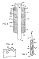
- FIG. 2 there is illustrated an alternative embodiment of this aspect of the present invention wherein electrode 130' is pre-shielded with a protective glass coating 140'.
- the electrode 130 1 has a moly collar 135 located near the tip end 131.
- the collar 135 may be threaded, shrink fitted or bolted onto the electrode 130'.
- a plurality of different glass-forming materials in the form of unconsolidated cullet or solid glass annular rings or annular cylinders 137A-137E, may be located axially of the electrode 130' along a selected length L' to grade the protective coating 140' thereof.
- an alumina tube 139 of sufficient length may be joined at a lower end 141 to the collar 135 for containing the materials therein.
- a fused silica material such as sold under the trademark V YCOR could be used for tube 139.
- an annular refractory cap or plug 145 may be sleeved over the rod 130' and located within the tube 139 to close a space containing the protective coating 140 1 therein.
- the plug 145 may be a packing material such as FIBERFRAX O Rope.
- a readily available extrudable silicone sealant 147 such as Dow Corning RTV 732 could be placed over refractory cap 145.
- a purge line 148 may be fitted through opening 149 in plug 145 and seal 147 for the introduction of a purge gas P interior the tube 139.
- a purge gas P protects the moly electrode during startup before the cullet rings 137A-137E melt. Thereafter, the melted material protects electrode from oxygen contamination.
- the electrode 130' illustrated in Figure 2 might be suitably clamped to the support collar 134 and slowly lowered through the batch 120 and into the molten glass 112. At such time, the various layers of protective materials 137A-137E would become melted or softened and adhere to the electrode 1301. It should be realized that, as in the embodiment of Figure 1, the protective layer 140 experiences a temperature gradient when placed in service. The temperature of the electrode 130' decreases as one moves axially therealong from the tip 131 to the point 133 near where it is supported by collar 134. Different glass compositions may be used for the rings 137A-137E forming protective layer 140', each having a different softening and annealing point. Each will be susceptible to some viscous flow at various temperatures.
- each will exhibit the proper characteristics at its anticipated operating temperature.
- the glasses as hereinabove set forth, there is less likelihood of thermally shocking the protective layer 140' over the temperature gradient therealong.
- the batch layer 120 acts as an insulator from the high heat generated within the bath of molten glass 112, the protective coating 140' will remain relatively intact even though it is softened.
- Example 1 is thought to set forth a suitable embodiment of a graded protective coating 140' beginning with the lower ring 137A or relatively softer glass and progressing to the uppermost ring 137E of relatively harder glass as follows:
- the present invention also contemplates the use of a borosilicate glass tube 139 such as Corning Code 7052 having an expansion comparable with the moly.
- the tube 139 would be sealed directly to the electrode 130' without the cullet fill 137A-137E.
- the electrode 130' should be preheated in order to prevent thermal shock.
- Electrode 130' may be prefabricated for quick insertion into the furnace 110 without any other preparation.
- the tube 139 not only contains therewithin the protective layer 140' (if in granular form) , but also provides for some protection of the protective layer 140' at least until it is consolidated during operation of the furnace 110.
- the moly collar 135 would normally be located below the level of the free surface 118 of the bath 112 shown in Figure 1, and thus, is protected from oxidation by its immersion in the molten glass 112.
- An electrode 130" may have an axial bore 150 drilled or formed therein.
- the bore 150 extends generally lengthwise thereof from an open upper end 151 to near tip 152 thereof.
- a purge line 153 may be located in the open end 151 and a purge fluid P introduced therein.
- hydrogen or other gases inert with respect to moly will diffuse therethrough as shown by dotted arrow Pd.
- This embodiment when dipped according to the invention is additionally protected from oxidation without undue energy and materials costs.
Landscapes
- Chemical & Material Sciences (AREA)
- Engineering & Computer Science (AREA)
- Materials Engineering (AREA)
- Organic Chemistry (AREA)
- Chemical Kinetics & Catalysis (AREA)
- Electrochemistry (AREA)
- Physics & Mathematics (AREA)
- Thermal Sciences (AREA)
- Glass Melting And Manufacturing (AREA)
- Furnace Details (AREA)
Applications Claiming Priority (6)
| Application Number | Priority Date | Filing Date | Title |
|---|---|---|---|
| US31799681A | 1981-11-04 | 1981-11-04 | |
| US317995 | 1981-11-04 | ||
| US06/317,994 US4413346A (en) | 1981-11-04 | 1981-11-04 | Glass-melting furnace with batch electrodes |
| US317996 | 1981-11-04 | ||
| US06/317,995 US4429402A (en) | 1981-11-04 | 1981-11-04 | Devices for use in a glass-melting furnace |
| US317994 | 1999-05-25 |
Related Parent Applications (1)
| Application Number | Title | Priority Date | Filing Date |
|---|---|---|---|
| EP82305861.5 Division | 1982-11-04 |
Publications (1)
| Publication Number | Publication Date |
|---|---|
| EP0164809A1 true EP0164809A1 (de) | 1985-12-18 |
Family
ID=27405965
Family Applications (3)
| Application Number | Title | Priority Date | Filing Date |
|---|---|---|---|
| EP82305861A Ceased EP0078715A1 (de) | 1981-11-04 | 1982-11-04 | Glasschmelzöfen |
| EP85200916A Withdrawn EP0164809A1 (de) | 1981-11-04 | 1982-11-04 | Verfahren zum Schützen oder Abschirmen einer Vorrichtung gegen Sauerstoff in einer Glasschmelzwanne |
| EP87201869A Withdrawn EP0261749A1 (de) | 1981-11-04 | 1982-11-04 | Verfahren zum Schützen eines Systems vor Sauerstoff in einem Glasschmelzofen und durch dieses Verfahren geschützte Vorrichtung |
Family Applications Before (1)
| Application Number | Title | Priority Date | Filing Date |
|---|---|---|---|
| EP82305861A Ceased EP0078715A1 (de) | 1981-11-04 | 1982-11-04 | Glasschmelzöfen |
Family Applications After (1)
| Application Number | Title | Priority Date | Filing Date |
|---|---|---|---|
| EP87201869A Withdrawn EP0261749A1 (de) | 1981-11-04 | 1982-11-04 | Verfahren zum Schützen eines Systems vor Sauerstoff in einem Glasschmelzofen und durch dieses Verfahren geschützte Vorrichtung |
Country Status (2)
| Country | Link |
|---|---|
| EP (3) | EP0078715A1 (de) |
| CA (1) | CA1202057A (de) |
Cited By (2)
| Publication number | Priority date | Publication date | Assignee | Title |
|---|---|---|---|---|
| AT397241B (de) * | 1986-06-06 | 1994-02-25 | Saint Gobain Rech | Elektroschmelzverfahren für glas |
| EP0717010A3 (de) * | 1994-12-17 | 1996-09-11 | Sorg Gmbh & Co Kg | Elektrodenanordnung für Glas-Wannenöfen |
Families Citing this family (4)
| Publication number | Priority date | Publication date | Assignee | Title |
|---|---|---|---|---|
| US4752938A (en) * | 1984-04-12 | 1988-06-21 | Corning Glass Works | Baffled glass melting furnaces |
| PL427601A1 (pl) * | 2018-10-30 | 2020-05-04 | Forglass Spółka Z Ograniczoną Odpowiedzialnością | Sposób ciągłego intensywnego wytapiania szkła |
| CN110357397A (zh) * | 2019-07-09 | 2019-10-22 | 东旭科技集团有限公司 | 电助熔冷却水套 |
| CN114751625A (zh) * | 2022-04-27 | 2022-07-15 | 陕西彩虹工业智能科技有限公司 | 一种耐高温电极加热砖的制备及玻璃窑炉内玻璃加工方法 |
Citations (4)
| Publication number | Priority date | Publication date | Assignee | Title |
|---|---|---|---|---|
| DE889337C (de) * | 1944-09-01 | 1953-09-10 | Ragnar Tanberg | Elektroden fuer elektrische Schmelzoefen, besonders Glasschmelzoefen |
| GB960032A (en) * | 1961-02-17 | 1964-06-10 | Siemens Ag | Improvements in or relating to closure devices for melt outlets of melting apparatus |
| US3884669A (en) * | 1971-11-03 | 1975-05-20 | Pilkington Brothers Ltd | Refractory elements |
| US3983309A (en) * | 1975-05-16 | 1976-09-28 | Johns-Manville Corporation | Primary electrode arrangement for high temperature melting furnace |
Family Cites Families (2)
| Publication number | Priority date | Publication date | Assignee | Title |
|---|---|---|---|---|
| US2263549A (en) * | 1938-08-05 | 1941-11-18 | Saint Gobain | Electrical heating of liquid baths |
| GB568469A (en) * | 1943-07-02 | 1945-04-06 | Gen Electric Co Ltd | Improvements in glass of low thermal expansion |
-
1982
- 1982-06-29 CA CA000406240A patent/CA1202057A/en not_active Expired
- 1982-11-04 EP EP82305861A patent/EP0078715A1/de not_active Ceased
- 1982-11-04 EP EP85200916A patent/EP0164809A1/de not_active Withdrawn
- 1982-11-04 EP EP87201869A patent/EP0261749A1/de not_active Withdrawn
Patent Citations (4)
| Publication number | Priority date | Publication date | Assignee | Title |
|---|---|---|---|---|
| DE889337C (de) * | 1944-09-01 | 1953-09-10 | Ragnar Tanberg | Elektroden fuer elektrische Schmelzoefen, besonders Glasschmelzoefen |
| GB960032A (en) * | 1961-02-17 | 1964-06-10 | Siemens Ag | Improvements in or relating to closure devices for melt outlets of melting apparatus |
| US3884669A (en) * | 1971-11-03 | 1975-05-20 | Pilkington Brothers Ltd | Refractory elements |
| US3983309A (en) * | 1975-05-16 | 1976-09-28 | Johns-Manville Corporation | Primary electrode arrangement for high temperature melting furnace |
Cited By (2)
| Publication number | Priority date | Publication date | Assignee | Title |
|---|---|---|---|---|
| AT397241B (de) * | 1986-06-06 | 1994-02-25 | Saint Gobain Rech | Elektroschmelzverfahren für glas |
| EP0717010A3 (de) * | 1994-12-17 | 1996-09-11 | Sorg Gmbh & Co Kg | Elektrodenanordnung für Glas-Wannenöfen |
Also Published As
| Publication number | Publication date |
|---|---|
| CA1202057A (en) | 1986-03-18 |
| EP0078715A1 (de) | 1983-05-11 |
| EP0261749A1 (de) | 1988-03-30 |
Similar Documents
| Publication | Publication Date | Title |
|---|---|---|
| US4366571A (en) | Electric furnace construction | |
| JP5425473B2 (ja) | 溶融物の温度操作方法 | |
| KR100626467B1 (ko) | 실리카 용융로, 석영 부재 및 석영 부재 형성 방법 | |
| US3717450A (en) | Furnace for manufacture of striationfree quartz tubing | |
| US4429402A (en) | Devices for use in a glass-melting furnace | |
| EP0471152B1 (de) | Verfahren zum Herstellen von Glasgegenständen | |
| EP0164809A1 (de) | Verfahren zum Schützen oder Abschirmen einer Vorrichtung gegen Sauerstoff in einer Glasschmelzwanne | |
| US20080128271A1 (en) | Apparatus for Rapid Startup During In-Container Vitrification | |
| US3659029A (en) | Electrical high-temperature melting furnace | |
| EP1484770A1 (de) | Glasschmelzer und Verfahren zum Betreiben eines solchen | |
| GB2193070A (en) | Electric glass melting furnace | |
| US1897973A (en) | Method of and apparatus for melting glass | |
| CN1235819C (zh) | 无机物的熔融或提纯装置 | |
| US3230060A (en) | Glass feeding | |
| US3723287A (en) | Apparatus for producing aluminum from alumina | |
| JPS5884130A (ja) | ガラス溶融炉およびその作動方法 | |
| US9247586B2 (en) | Unit for conductively heatable melting | |
| CA1296070C (en) | Electric melter for high electrical resistivity glass materials | |
| US3198615A (en) | Method and apparatus for melting heat-softenable materials | |
| JP3655308B2 (ja) | 電気的溶融装置 | |
| US4430109A (en) | Method of regulating fuel and air flow to a glass melting furnace | |
| CA1212235A (en) | Glass-melting furnaces | |
| US5887015A (en) | Heater mechanism for crystal pulling apparatus | |
| SU1766266A3 (ru) | Катод дл электролитического рафинировани алюмини по трехслойному методу и способ подготовки катода | |
| US3381078A (en) | Electrode device for electric furnaces |
Legal Events
| Date | Code | Title | Description |
|---|---|---|---|
| PUAI | Public reference made under article 153(3) epc to a published international application that has entered the european phase |
Free format text: ORIGINAL CODE: 0009012 |
|
| AC | Divisional application: reference to earlier application |
Ref document number: 78715 Country of ref document: EP |
|
| AK | Designated contracting states |
Designated state(s): BE DE FR GB IT NL |
|
| 17P | Request for examination filed |
Effective date: 19860527 |
|
| 17Q | First examination report despatched |
Effective date: 19870223 |
|
| STAA | Information on the status of an ep patent application or granted ep patent |
Free format text: STATUS: THE APPLICATION IS DEEMED TO BE WITHDRAWN |
|
| 18D | Application deemed to be withdrawn |
Effective date: 19881012 |
|
| RIN1 | Information on inventor provided before grant (corrected) |
Inventor name: CARLEY, HAROLD JAMES Inventor name: PALMQUIST, RONALD WILLIAM |