EP0165171A2 - Drahtkühlvorrichtung für Drahtziehmaschine - Google Patents
Drahtkühlvorrichtung für Drahtziehmaschine Download PDFInfo
- Publication number
- EP0165171A2 EP0165171A2 EP85401101A EP85401101A EP0165171A2 EP 0165171 A2 EP0165171 A2 EP 0165171A2 EP 85401101 A EP85401101 A EP 85401101A EP 85401101 A EP85401101 A EP 85401101A EP 0165171 A2 EP0165171 A2 EP 0165171A2
- Authority
- EP
- European Patent Office
- Prior art keywords
- wire
- capstan
- cooling
- box
- turns
- Prior art date
- Legal status (The legal status is an assumption and is not a legal conclusion. Google has not performed a legal analysis and makes no representation as to the accuracy of the status listed.)
- Granted
Links
Images
Classifications
-
- B—PERFORMING OPERATIONS; TRANSPORTING
- B21—MECHANICAL METAL-WORKING WITHOUT ESSENTIALLY REMOVING MATERIAL; PUNCHING METAL
- B21C—MANUFACTURE OF METAL SHEETS, WIRE, RODS, TUBES, PROFILES OR LIKE SEMI-MANUFACTURED PRODUCTS OTHERWISE THAN BY ROLLING; AUXILIARY OPERATIONS USED IN CONNECTION WITH METAL-WORKING WITHOUT ESSENTIALLY REMOVING MATERIAL
- B21C9/00—Cooling, heating or lubricating drawing material
-
- B—PERFORMING OPERATIONS; TRANSPORTING
- B21—MECHANICAL METAL-WORKING WITHOUT ESSENTIALLY REMOVING MATERIAL; PUNCHING METAL
- B21C—MANUFACTURE OF METAL SHEETS, WIRE, RODS, TUBES, PROFILES OR LIKE SEMI-MANUFACTURED PRODUCTS OTHERWISE THAN BY ROLLING; AUXILIARY OPERATIONS USED IN CONNECTION WITH METAL-WORKING WITHOUT ESSENTIALLY REMOVING MATERIAL
- B21C1/00—Manufacture of metal sheets, wire, rods, tubes or like semi-manufactured products by drawing
- B21C1/02—Drawing metal wire or like flexible metallic material by drawing machines or apparatus in which the drawing action is effected by drums
- B21C1/14—Drums, e.g. capstans; Connection of grippers thereto; Grippers specially adapted for drawing machines or apparatus of the drum type; Couplings specially adapted for these drums
Definitions
- the present invention relates to a wire cooling device for a wire drawing machine.
- wire cooling devices which are basically of two kinds: indirect cooling devices and direct cooling devices.
- Indirect cooling consists in cooling, by circulation of liquid, the tools in contact with the wire, that is to say the die and the traction capstan.
- the residence time of an elementary slice of wire in the die being extremely short, this cooling is very limited.
- the capstan allows a large number of turns to be stored, thus increasing the contact surface between the hot wire and the cooled capstan. This cooling is therefore more efficient but is limited by its principle of heat exchange on the one hand, and by the purely linear contact between the round wire and the cylindrical capstan on the other hand.
- Another method consists in spraying the coolant from the outside directly onto the turns of wire accumulated on the capstan, which allows longer exposure of the wire to cooling. Such a process would be effective, but the runoff and centrifugation of liquid and the humid atmosphere surrounding the machine are practically not acceptable.
- a cooling box in the form of a circular sector and of tubular section, supplied with cooling liquid and arranged in a manner on the one hand, to direct the cooling fluid towards the turns of the wire wound on the capstan, on the other hand, to collect the fluid, after its cooling action, with a view to its evacuation.
- the box comprises, directed towards the capstan a wall, onto which opens the coolant supply pipe, arranged so as to direct and distribute the coolant in space, constituting the cooling zone between it and the turns of wire wound on the capstan.
- the box has, opening onto the space constituting the cooling zone and on either side of the distribution wall, a coolant collection and expansion chamber, projected by the pressure and the centrifugal force after its cooling action and the steam produced by the cooling, with a view to their evacuation by a pipe with which the box is provided, advantageously connected to a suction system.
- the box is mounted so that its spacing from the capstan of the machine can be varied.
- the box is removed from the machine, manually or by any other means such as an actuator, etc. while, during the drawing work of the machine the box is kept at a sufficient distance from the capstan so that the turns of wire stacked on the capstan do not touch the box.
- a thin strip of coolant is thus formed between the turns of the wire and the internal distribution wall of the box.
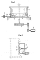
- the wire drawing machine comprises a capstan 1 which is presented as a cylindrical body driven in rotation by a motor 2 and a transmission 3.
- the inner part of the capstan 4 draws the wire 4a through the die 5 placed upstream.
- Several turns are formed on the capstan by the operator when threading the machine in order to obtain the capstan effect necessary for drawing and to cover the cooling area on the capstan.
- the turns of wire go up along the capstan before going to the downstream drawing block, in the case of multiple drawing machines or to the devices for receiving the wire, in the case of the last block of the multiple machines or in the case of monoblock drawing machines.
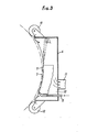
- a box 6 in the form of a circular sector and of tubular section is arranged near the bottom part of the capstan 1 and concentrically with the latter.
- the box has, on its face facing the capstan, a wall 7 to which is brought, by one or more, pipes 8, the coolant.
- the wall 7 is arranged so as to direct the coolant towards, and distribute it in, the space 9 formed between the wall and the turns of wire wound on the capstan 1.
- the distribution wall 7 is of a height such that a sufficient number of turns of wire is subjected to the direct cooling effect of the thin blade of liquid introduced into the space 9, constituting the cooling zone.
- the box has, opening onto the space 9, on either side of the distribution wall 7, a chamber 10 for collecting and expanding in which are sprayed by the pressure and the centrifugal force the liquid used for cooling and the vapor generated during cooling. These cooling residues are removed by a pipe 11 advantageously connected to a suction system (not shown).
- the box is mounted so that its position relative to the capstan can be changed for example in view of its spacing from the capstan during threading of the machine.
Landscapes
- Engineering & Computer Science (AREA)
- Mechanical Engineering (AREA)
- Metal Extraction Processes (AREA)
- Devices That Are Associated With Refrigeration Equipment (AREA)
- Defrosting Systems (AREA)
Priority Applications (1)
| Application Number | Priority Date | Filing Date | Title |
|---|---|---|---|
| AT85401101T ATE57632T1 (de) | 1984-06-15 | 1985-06-04 | Drahtkuehlvorrichtung fuer drahtziehmaschine. |
Applications Claiming Priority (2)
| Application Number | Priority Date | Filing Date | Title |
|---|---|---|---|
| FR8409426 | 1984-06-15 | ||
| FR8409426A FR2565855B1 (fr) | 1984-06-15 | 1984-06-15 | Dispositif de refroidissement de fil pour machine a trefiler |
Publications (3)
| Publication Number | Publication Date |
|---|---|
| EP0165171A2 true EP0165171A2 (de) | 1985-12-18 |
| EP0165171A3 EP0165171A3 (en) | 1988-01-13 |
| EP0165171B1 EP0165171B1 (de) | 1990-10-24 |
Family
ID=9305086
Family Applications (1)
| Application Number | Title | Priority Date | Filing Date |
|---|---|---|---|
| EP85401101A Expired - Lifetime EP0165171B1 (de) | 1984-06-15 | 1985-06-04 | Drahtkühlvorrichtung für Drahtziehmaschine |
Country Status (7)
| Country | Link |
|---|---|
| US (1) | US4620433A (de) |
| EP (1) | EP0165171B1 (de) |
| JP (1) | JPS6114017A (de) |
| AT (1) | ATE57632T1 (de) |
| DE (1) | DE3580195D1 (de) |
| ES (1) | ES8606801A1 (de) |
| FR (1) | FR2565855B1 (de) |
Families Citing this family (1)
| Publication number | Priority date | Publication date | Assignee | Title |
|---|---|---|---|---|
| DE102006017671B4 (de) * | 2006-04-12 | 2015-05-28 | Ernst Koch Gmbh & Co Kg | Drahtziehvorrichtung |
Family Cites Families (7)
| Publication number | Priority date | Publication date | Assignee | Title |
|---|---|---|---|---|
| US883695A (en) * | 1906-03-19 | 1908-04-07 | Chrome Steel Works | Die. |
| GB1249926A (en) * | 1969-03-25 | 1971-10-13 | British Iron Steel Research | Wire drawing |
| DE2020926A1 (de) * | 1970-04-29 | 1971-11-18 | Herborn Kg Maschf | Kuehlanordnung an Drahtziehmaschinen |
| US3774436A (en) * | 1972-03-22 | 1973-11-27 | E Tviksta | Device for metal treatment |
| SE7800058L (sv) * | 1977-01-14 | 1978-07-15 | Hi Draw Machinery Ltd | Forfarande och anordning for att kyla dragna, langstreckta material |
| GB2038219B (en) * | 1978-12-12 | 1982-08-18 | Marshall Richards Barcro Ltd | Wire drawing method and apparatus |
| GB2049519B (en) * | 1979-05-08 | 1983-01-26 | Masrhall Richards Barcro Ltd | Wire drawing |
-
1984
- 1984-06-15 FR FR8409426A patent/FR2565855B1/fr not_active Expired
-
1985
- 1985-05-29 ES ES543632A patent/ES8606801A1/es not_active Expired
- 1985-06-04 DE DE8585401101T patent/DE3580195D1/de not_active Expired - Fee Related
- 1985-06-04 AT AT85401101T patent/ATE57632T1/de not_active IP Right Cessation
- 1985-06-04 EP EP85401101A patent/EP0165171B1/de not_active Expired - Lifetime
- 1985-06-12 JP JP60127909A patent/JPS6114017A/ja active Pending
- 1985-06-12 US US06/743,961 patent/US4620433A/en not_active Expired - Fee Related
Also Published As
| Publication number | Publication date |
|---|---|
| ES543632A0 (es) | 1986-06-01 |
| US4620433A (en) | 1986-11-04 |
| EP0165171A3 (en) | 1988-01-13 |
| FR2565855A1 (fr) | 1985-12-20 |
| ES8606801A1 (es) | 1986-06-01 |
| ATE57632T1 (de) | 1990-11-15 |
| FR2565855B1 (fr) | 1988-12-02 |
| JPS6114017A (ja) | 1986-01-22 |
| EP0165171B1 (de) | 1990-10-24 |
| DE3580195D1 (de) | 1990-11-29 |
Similar Documents
| Publication | Publication Date | Title |
|---|---|---|
| EP0428464B1 (de) | Zylinder für Einzel- oder Doppelrollenstranggiessvorrichtung | |
| EP1337681B1 (de) | Vorrichtung zur tauchbeschichtung eines metallstreifens | |
| FR2568495A1 (fr) | Dispositif de brossage et le lubrification en continu de cylindres de laminoirs pour produits plats lamines. | |
| EP0165171B1 (de) | Drahtkühlvorrichtung für Drahtziehmaschine | |
| FR2599996A1 (fr) | Procede et appareil pour la production en continu de tubes metalliques soudes | |
| US4537243A (en) | Method of and apparatus for steam preheating endless flexible casting belt | |
| EP0116498B1 (de) | Drahtkühlvorrichtung für Drahtziehmaschine | |
| FR2833871A1 (fr) | Procede et installation de fabrication de bandes metalliques a partir de bandes coulees directement a partir de metal liquide | |
| FR2494160A1 (fr) | Procede et dispositif pour le traitement d'objets par abrasion, notamment d'objets peints, et son application au traitement de depolissage de carrosseries de vehicules | |
| FR3111164A1 (fr) | Système d’élimination de dépôt interne dans un tube central d’évacuation de turboréacteur | |
| FR2575092A1 (fr) | Procede et appareil pour decalaminer un feuillard chaud dans un laminoir | |
| CH497220A (fr) | Installation de refroidissement d'un moule de coulée | |
| FR2702973A1 (fr) | Procédé et dispositif de décalaminage d'un fil métallique. | |
| EP1158177B1 (de) | Lüfter | |
| EP0327526A1 (de) | Vorrichtung zum Kühlen eines Metalls während des Giessens | |
| BE473746A (fr) | Perfectionnements a la fabrication de feutres, notamment en fibres de verre ou autres fibres minerales | |
| FR2494626A1 (fr) | Procede et appareil de fabrication d'elements de turbulence en resine synthetique | |
| FR2742683A1 (fr) | Dispositif tournant de coulee continue | |
| EP0290423B1 (de) | Vorrichtung zur kontinuierlichen Herstellung eines dünnen Metallbands | |
| FR2551997A1 (fr) | Dispositif pour cintrer des tubes ou des articles semblables | |
| CA2472034A1 (fr) | Procede et dispositif de refroidissement d'une veine de fluide gazeux, et procede de refroidissement d'articles | |
| CH647172A5 (fr) | Machine de coulee continue de metal en fusion. | |
| EP1894479B1 (de) | Vorrichtung zum kühlen von flüssigen oder teigartigen produkten, die portioniermittel mit hilfe von vorschneidevorrichtungen umfasst und entsprechendes anwendungsverfahren | |
| BE1000528A6 (fr) | Procede et dispositif de fabrication en continu d'une bande metallique mince. | |
| KR820001706B1 (ko) | 선재, 금속봉등의 표면층을 스트리핑(stripping)하는 방법 |
Legal Events
| Date | Code | Title | Description |
|---|---|---|---|
| PUAI | Public reference made under article 153(3) epc to a published international application that has entered the european phase |
Free format text: ORIGINAL CODE: 0009012 |
|
| AK | Designated contracting states |
Designated state(s): AT BE CH DE GB IT LI LU NL SE |
|
| 17P | Request for examination filed |
Effective date: 19860321 |
|
| PUAL | Search report despatched |
Free format text: ORIGINAL CODE: 0009013 |
|
| AK | Designated contracting states |
Kind code of ref document: A3 Designated state(s): AT BE CH DE GB IT LI LU NL SE |
|
| 17Q | First examination report despatched |
Effective date: 19890228 |
|
| GRAA | (expected) grant |
Free format text: ORIGINAL CODE: 0009210 |
|
| ITF | It: translation for a ep patent filed | ||
| AK | Designated contracting states |
Kind code of ref document: B1 Designated state(s): AT BE CH DE GB IT LI LU NL SE |
|
| PG25 | Lapsed in a contracting state [announced via postgrant information from national office to epo] |
Ref country code: SE Effective date: 19901024 Ref country code: NL Effective date: 19901024 Ref country code: AT Effective date: 19901024 |
|
| REF | Corresponds to: |
Ref document number: 57632 Country of ref document: AT Date of ref document: 19901115 Kind code of ref document: T |
|
| GBT | Gb: translation of ep patent filed (gb section 77(6)(a)/1977) | ||
| REF | Corresponds to: |
Ref document number: 3580195 Country of ref document: DE Date of ref document: 19901129 |
|
| NLV1 | Nl: lapsed or annulled due to failure to fulfill the requirements of art. 29p and 29m of the patents act | ||
| PG25 | Lapsed in a contracting state [announced via postgrant information from national office to epo] |
Ref country code: GB Effective date: 19910604 |
|
| PG25 | Lapsed in a contracting state [announced via postgrant information from national office to epo] |
Ref country code: LU Free format text: LAPSE BECAUSE OF NON-PAYMENT OF DUE FEES Effective date: 19910630 Ref country code: LI Effective date: 19910630 Ref country code: CH Effective date: 19910630 Ref country code: BE Effective date: 19910630 |
|
| PLBE | No opposition filed within time limit |
Free format text: ORIGINAL CODE: 0009261 |
|
| STAA | Information on the status of an ep patent application or granted ep patent |
Free format text: STATUS: NO OPPOSITION FILED WITHIN TIME LIMIT |
|
| 26N | No opposition filed | ||
| BERE | Be: lapsed |
Owner name: OFFICE TECHNIQUE DES TREFILES Effective date: 19910630 |
|
| GBPC | Gb: european patent ceased through non-payment of renewal fee | ||
| REG | Reference to a national code |
Ref country code: CH Ref legal event code: PL |
|
| PG25 | Lapsed in a contracting state [announced via postgrant information from national office to epo] |
Ref country code: DE Effective date: 19920401 |