EP0165325A1 - Méthode et appareil pour le contrôle acoustique d'un mécanisme d'ajustage pour un dispositif optique - Google Patents
Méthode et appareil pour le contrôle acoustique d'un mécanisme d'ajustage pour un dispositif optique Download PDFInfo
- Publication number
- EP0165325A1 EP0165325A1 EP84106945A EP84106945A EP0165325A1 EP 0165325 A1 EP0165325 A1 EP 0165325A1 EP 84106945 A EP84106945 A EP 84106945A EP 84106945 A EP84106945 A EP 84106945A EP 0165325 A1 EP0165325 A1 EP 0165325A1
- Authority
- EP
- European Patent Office
- Prior art keywords
- intensity
- deviations
- values
- stage
- surface elements
- Prior art date
- Legal status (The legal status is an assumption and is not a legal conclusion. Google has not performed a legal analysis and makes no representation as to the accuracy of the status listed.)
- Granted
Links
Images
Classifications
-
- G—PHYSICS
- G01—MEASURING; TESTING
- G01J—MEASUREMENT OF INTENSITY, VELOCITY, SPECTRAL CONTENT, POLARISATION, PHASE OR PULSE CHARACTERISTICS OF INFRARED, VISIBLE OR ULTRAVIOLET LIGHT; COLORIMETRY; RADIATION PYROMETRY
- G01J1/00—Photometry, e.g. photographic exposure meter
- G01J1/42—Photometry, e.g. photographic exposure meter using electric radiation detectors
- G01J1/4257—Photometry, e.g. photographic exposure meter using electric radiation detectors applied to monitoring the characteristics of a beam, e.g. laser beam, headlamp beam
Definitions
- the present invention relates to the fields of imaging optics and laser optics and relates to optical devices in which the intensity distribution in a light bundle, in particular in a laser light bundle, is adjusted transversely to the optical axis of the light bundle with respect to a reference plane located in the beam path got to.
- the intensity distribution, the position or the direction of a light beam is influenced by optical components such as mirrors, deflection prisms, lenses, optically transparent flat and wedge plates, grating, holographic deflector screens, acoustic multifrequency modulators or acousto-optical reflectors.
- optical components such as mirrors, deflection prisms, lenses, optically transparent flat and wedge plates, grating, holographic deflector screens, acoustic multifrequency modulators or acousto-optical reflectors.
- the light source itself can also be moved.
- the adjustment of a light beam with regard to its intensity distribution, its position or its direction is carried out by means of suitable adjustment means in the form of mechanical adjustments such as, for. B. mirror mounts or in the form of electromechanical adjustments such. B. Piezo drives.
- the known adjustment aids are not precise enough, sometimes do not provide a clear indication of an optimal adjustment and are sometimes difficult to handle.
- the present invention is therefore based on the object of specifying a method and a device for acoustically checking the intensity distribution in a light bundle with respect to a reference plane located in the beam path transverse to the optical axis of the light bundle, with the aid of which the adjustment can be carried out more easily and more precisely, and also with which the necessary steps for an optimal adjustment according to size and direction are signaled.
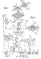
- Fig. 1 shows an embodiment of a device for acoustic monitoring or control of the adjustment of a light beam, for. B. a laser light beam, with respect to its intensity distribution in a predetermined reference plane transverse to the optical axis of the light beam.
- An example of a desired intensity distribution in reference plane 3 is shown in FIG. 2, in which the target intensity values I for s the individual surface elements 4 of plane 3 defined by coordinate values x and v are shown as a spatial function.
- a change in the intensity distribution in the beam 1 can be achieved, for example, by moving lenses or prisms in the beam path of the light beam 1.
- the light measuring surface 7 is e.g. B.
- each planar element 4 within the reference plane 3 a positionally matching photodiode is assigned within the photodiode matrix, so that the individual output signals of the photodiodes correspond to the measured, location-dependent actual intensity values I i - f (x, y) for the surface elements 4 of the reference plane 3.
- the light measuring surface 7 can of course also be arranged in the beam path of the light beam 1.
- a clock generator 12 To control the analog multiplexer 9, a clock generator 12 generates a clock sequence T 0 , which is counted into a fast cyclic counter 14 via a clock input 13. At the data output 15 of the fast cyclic counter 14 there is a digital control signal S 1 with n different bit combinations which are repeated in the individual measuring cycles after n counted clock cycles of the clock sequence T 0 . At the same time, a control signal S 2 "measuring cycle end" is generated at a signal output 16 of the counter 14 at the end of a measuring cycle. The digital control signal S 1 is given to switch through the measured actual intensity values I i in the individual measuring cycles to a control input 17 of the analog multiplexer 9, with the actual intensity value I. of a specific one being given with each bit combination of the control signal S 1 Surface element 4 of the reference plane 3 is switched through to the A / D converter 11.
- the actual intensity values I i of the individual surface elements 4 digitized in the A / D converter 11 are normalized in a normalization stage 18 in the exemplary embodiment shown, since in most cases the absolute, but the relative intensity distribution is of interest.
- the standardization stage 18 consists of an electronic switch 19 symbolized by a mechanical switch, an adder stage 20 with adder and subtotals memory and a divider stage 21.
- the electric switch 19 is in each case at the end of a measuring cycle by the counter 14 generated control signal S 2 "measurement cycle end" switched.
- the clock sequence T 0 obtained in the clock q over 12 is simultaneously counted into an address counter 25 via a clock input 24.
- the address counter 25 is set so that it calls up the corresponding addresses for the individual standardized target intensity values I s only in each even-numbered measuring cycle via its address output 26 and via the address input 27 of the target value memory 5, the to the read command input 28 of the setpoint memory 5 clock sequence T 0 is used as a read clock sequence.
- the intensity difference values ⁇ I. f (x, y) between target and actual intensity values.
- the target value memory 5 and the normalization stage 18 are connected to a difference stage 22, in which the intensity difference values ⁇ I. be formed.
- the intensity difference values ⁇ I. are modified according to a function in an advantageous manner, in the exemplary embodiment, are guadroned in a downstream squaring stage 29, whereby the sign of the difference values is eliminated and the evaluation of the deviations becomes more favorable.
- the q- corrected difference values (41) 2 are written into a buffer memory 31 via a data input 30 and temporarily stored there.
- the address counter 25 simultaneously calls up the addresses of the buffer memory 31 via the write address input 32, while the clock sequence q e T 0 is given as a write clock sequence to the write command input 33 of the buffer memory 31.
- the auadratic difference values ( ⁇ I. ) 2 are in slow cycles, e.g. B. with a cycle time of one second, read from the buffer memory 31.
- a clock generator 34 generates a clock sequence T 1 which is fed to the clock input 35 of a slow, cyclical address counter 36.
- the address counter 36 generates the read addresses which are fed to the read address input 37 of the buffer memory 31.
- the clock sequence T 1 used as a read clock sequence is fed to the buffer memory 31 via the read command input 38.
- the digital quadratic intensity difference values ( ⁇ I. ) 2 are converted in a downstream D / A converter 39 into analog voltage values, which represent a measure of the quadratic deviations of the actual intensity distribution from the target intensity distribution.
- a periodic oscillation is generated, the frequency, amplitude, duty cycle or duty cycle of the quadratic intensity difference values ( ⁇ I. ) 2 is modified. Then the modified oscillation is converted into a corresponding measuring tone, the pitch, volume, interrupter frequency or duration of interruption of the respective auadratic intensity difference values ( ⁇ I. ) 2 depend.
- the quadratic intensity difference values ( ⁇ I. ) 2 depending on the quadratic intensity difference values ( ⁇ I. ) 2 the frequency of the vibration and thus the pitch of the measuring tone varies.
- a voltage-controlled oscillator 40 ( V CO) is provided, to which the quadratic intensity difference values ( ⁇ I. ) 2 can be supplied as a control signal.
- Overvoltage g sqe horrte oscillator 40 generates a sinusoidal output oscillation whose Freauenz depends on the fed control signal.
- the output oscillation of the voltage-controlled oscillator 40 is passed to an amplifier 42, again symbolized as a mechanical switch, to an amplifier 42, amplified there and, for example, by means of an electroacoustic transducer.
- B. made audible in the form of a loudspeaker 43 as a measuring tone.
- the relationship between the quadratic intensity difference values ( ⁇ I. ) 2 and the pitch is taken, for example, so that the height of the measuring tone decreases as the square intensity difference values become smaller. Since the individual quadratic intensity difference values ( ⁇ I.
- the individual measurement tones for the surface elements 4 of the reference plane 3 are also generated at an interval of seconds.
- the acoustic over Monitoring the adjustment of the light beam 1 is thus a high measuring tone in a surface element 4 with a large intensity deviation and a low measuring tone is generated in a surface element 4 with a low intensity deviation, the deep measuring tones predominating with increasing intensity agreement for all surface elements 4.
- the quadratic intensity difference values ( ⁇ I. ) 2 given simultaneously via a switch 44 to an adding stage 45 of a threshold circuit 46.
- the quadratic intensity difference values ( ⁇ I. ) 2 of a measuring cycle a total value ⁇ ( ⁇ I. ) 2 formed and stored in an internal register of the adder stage 45.
- a standardized limit value is entered into a register 47 of the threshold circuit 46 I. g loaded, which represents a permissible deviation of the actual intensity distribution from the desired target intensity distribution.
- a comparator 48 the total values ⁇ ( ⁇ I. ) 2 with the specified limit I.
- the comparator 48 outputs a control signal S 3 which switches the changeover switch 41 to the position shown in broken lines.
- the connection between the voltage-controlled oscillator 40 and the loudspeaker 43 is interrupted and the measuring tone, which is dependent on the quadratic difference value, is switched off.
- the loudspeaker 43 is connected to an oscillator 50 via the changeover switch 41 and an interrupter 49.
- the oscillator 50 generates an oscillation of z. B. 500 Hz, which is interrupted by the interrupter 49 periodically with a frequency of 5 Hz, for example, and is made audible in the loudspeaker 43 as a periodically interrupted continuous measuring tone.
- This Periodically interrupted continuous measuring tone signals that the desired agreement between target and actual intensity distribution has been reached. If a more precise adjustment than that specified by the current limit value Ig entered in register 47 is desired, a correspondingly smaller limit value can be used I. Load g into register 47. The adjustment using these limit values has the advantage that it can be specified by the manufacturer or user of such optical devices.
- the threshold circuit 46 can advantageously be deactivated by actuating the switch 44, so that the changeover switch 41 remains in the position shown.
- the measuring tone generated is still of the quadratic difference values ( ⁇ I. ) 2 dependent, the loudspeaker 43 emitting a deep continuous measuring tone when the desired and actual intensity distribution are matched.
- the type of measurement tone generation is not limited to the exemplary embodiment described.
- the standardization stage 18 is bypassed or is omitted entirely, so that the output of the A / D converter 11 is connected directly to an input of the differential stage 22. Then the setpoint memory 5 and the register 47 are loaded not with the normalized but with the absolute setpoints or limit values.
- the position of the light bundle 1 can also be advantageously adjusted, for example by only assigning a target intensity value I to the surface elements 4 of the reference plane 3, which corresponds to the cross-sectional area of the light bundle 1 in the desired position form.
- other submenus of the surface elements 4 can also be queried in a specific sequence for adjusting the position of the light beam 1.
Landscapes
- Physics & Mathematics (AREA)
- Optics & Photonics (AREA)
- General Physics & Mathematics (AREA)
- Spectroscopy & Molecular Physics (AREA)
- Photometry And Measurement Of Optical Pulse Characteristics (AREA)
- Measurement Of Mechanical Vibrations Or Ultrasonic Waves (AREA)
- Testing Of Optical Devices Or Fibers (AREA)
- Mounting And Adjusting Of Optical Elements (AREA)
- Length Measuring Devices By Optical Means (AREA)
- Stereophonic System (AREA)
- Circuit For Audible Band Transducer (AREA)
Priority Applications (7)
| Application Number | Priority Date | Filing Date | Title |
|---|---|---|---|
| AT84106945T ATE36756T1 (de) | 1984-06-18 | 1984-06-18 | Verfahren und einrichtung zur akustischen kontrolle von justiervorgaengen an optischen vorrichtungen. |
| DE8484106945T DE3473649D1 (en) | 1984-06-18 | 1984-06-18 | Method and appliance for the acoustic control of the adjustment of optical devices |
| EP84106945A EP0165325B1 (fr) | 1984-06-18 | 1984-06-18 | Méthode et appareil pour le contrôle acoustique d'un mécanisme d'ajustage pour un dispositif optique |
| US06/743,516 US4694150A (en) | 1984-06-18 | 1985-06-11 | Method and apparatus for acoustic supervision of adjustment operations at optical devices |
| SU853911197A SU1755719A3 (ru) | 1984-06-18 | 1985-06-17 | Способ контрол распределени интенсивности в поперечном сечении светового пучка и устройство дл его осуществлени |
| CA000484159A CA1220554A (fr) | 1984-06-18 | 1985-06-17 | Methode et appareil de surveillance acoustique d'operations de reglage de dispositifs optiques |
| JP13097285A JPS6140532A (ja) | 1984-06-18 | 1985-06-18 | 光束の強度分布調整の音響監視方法および装置 |
Applications Claiming Priority (1)
| Application Number | Priority Date | Filing Date | Title |
|---|---|---|---|
| EP84106945A EP0165325B1 (fr) | 1984-06-18 | 1984-06-18 | Méthode et appareil pour le contrôle acoustique d'un mécanisme d'ajustage pour un dispositif optique |
Publications (2)
| Publication Number | Publication Date |
|---|---|
| EP0165325A1 true EP0165325A1 (fr) | 1985-12-27 |
| EP0165325B1 EP0165325B1 (fr) | 1988-08-24 |
Family
ID=8191998
Family Applications (1)
| Application Number | Title | Priority Date | Filing Date |
|---|---|---|---|
| EP84106945A Expired EP0165325B1 (fr) | 1984-06-18 | 1984-06-18 | Méthode et appareil pour le contrôle acoustique d'un mécanisme d'ajustage pour un dispositif optique |
Country Status (7)
| Country | Link |
|---|---|
| US (1) | US4694150A (fr) |
| EP (1) | EP0165325B1 (fr) |
| JP (1) | JPS6140532A (fr) |
| AT (1) | ATE36756T1 (fr) |
| CA (1) | CA1220554A (fr) |
| DE (1) | DE3473649D1 (fr) |
| SU (1) | SU1755719A3 (fr) |
Cited By (1)
| Publication number | Priority date | Publication date | Assignee | Title |
|---|---|---|---|---|
| US11306895B2 (en) | 2010-08-31 | 2022-04-19 | Ideal Industries Lighting Llc | Troffer-style fixture |
Families Citing this family (7)
| Publication number | Priority date | Publication date | Assignee | Title |
|---|---|---|---|---|
| US4945221A (en) * | 1987-04-24 | 1990-07-31 | Laser Alignment, Inc. | Apparatus and method for controlling a hydraulic excavator |
| JPS6415632A (en) * | 1987-07-09 | 1989-01-19 | Sonoike Mfg | Laser beam analyzer |
| JPH0243511A (ja) * | 1988-08-04 | 1990-02-14 | Fuji Electric Co Ltd | イメージセンサ対の光学系との位置合わせ方法 |
| JPH04110023U (ja) * | 1991-03-06 | 1992-09-24 | 株式会社村田製作所 | 圧電共振子 |
| US5264905A (en) * | 1992-04-27 | 1993-11-23 | Grumman Aerospace Corporation | Electro-optic automated test equipment |
| JP2007000316A (ja) * | 2005-06-23 | 2007-01-11 | Hitachi Medical Corp | X線ct装置 |
| JP5628103B2 (ja) * | 2011-06-30 | 2014-11-19 | 富士フイルム株式会社 | 放射線検出器、放射線画像撮影システム、断線検出プログラム、及び断線検出方法 |
Citations (4)
| Publication number | Priority date | Publication date | Assignee | Title |
|---|---|---|---|---|
| US4081216A (en) * | 1976-06-25 | 1978-03-28 | The United States Of America As Represented By The Department Of Health, Education And Welfare | Ultrasonic transducer calibration |
| US4126834A (en) * | 1977-06-27 | 1978-11-21 | Gte Sylvania Incorporated | Bulk wave bragg cell |
| DE2850743A1 (de) * | 1978-11-23 | 1980-05-29 | Messerschmitt Boelkow Blohm | Opto-elektronische messung der sendestrahlrichtung eines lidars |
| DE3151834A1 (de) * | 1980-12-29 | 1982-08-12 | Universal Pioneer Corp., Tokyo | "servofokusvorrichtung in einem optischen abtastsystem |
Family Cites Families (2)
| Publication number | Priority date | Publication date | Assignee | Title |
|---|---|---|---|---|
| US3907435A (en) * | 1972-09-29 | 1975-09-23 | Laser Alignment | Light beam alignment target and method |
| US3972622A (en) * | 1974-09-19 | 1976-08-03 | New Hampshire Ball Bearings, Inc. | Electronic survey target |
-
1984
- 1984-06-18 EP EP84106945A patent/EP0165325B1/fr not_active Expired
- 1984-06-18 DE DE8484106945T patent/DE3473649D1/de not_active Expired
- 1984-06-18 AT AT84106945T patent/ATE36756T1/de not_active IP Right Cessation
-
1985
- 1985-06-11 US US06/743,516 patent/US4694150A/en not_active Expired - Lifetime
- 1985-06-17 CA CA000484159A patent/CA1220554A/fr not_active Expired
- 1985-06-17 SU SU853911197A patent/SU1755719A3/ru active
- 1985-06-18 JP JP13097285A patent/JPS6140532A/ja active Granted
Patent Citations (4)
| Publication number | Priority date | Publication date | Assignee | Title |
|---|---|---|---|---|
| US4081216A (en) * | 1976-06-25 | 1978-03-28 | The United States Of America As Represented By The Department Of Health, Education And Welfare | Ultrasonic transducer calibration |
| US4126834A (en) * | 1977-06-27 | 1978-11-21 | Gte Sylvania Incorporated | Bulk wave bragg cell |
| DE2850743A1 (de) * | 1978-11-23 | 1980-05-29 | Messerschmitt Boelkow Blohm | Opto-elektronische messung der sendestrahlrichtung eines lidars |
| DE3151834A1 (de) * | 1980-12-29 | 1982-08-12 | Universal Pioneer Corp., Tokyo | "servofokusvorrichtung in einem optischen abtastsystem |
Non-Patent Citations (1)
| Title |
|---|
| APPLIED OPTICS, Band 18, Nr. 17, 1 September 1979;H.P. LAYER "Acoustooptic modulator intensity servo", Seiten 2947-2949 * |
Cited By (1)
| Publication number | Priority date | Publication date | Assignee | Title |
|---|---|---|---|---|
| US11306895B2 (en) | 2010-08-31 | 2022-04-19 | Ideal Industries Lighting Llc | Troffer-style fixture |
Also Published As
| Publication number | Publication date |
|---|---|
| JPS6140532A (ja) | 1986-02-26 |
| ATE36756T1 (de) | 1988-09-15 |
| DE3473649D1 (en) | 1988-09-29 |
| EP0165325B1 (fr) | 1988-08-24 |
| SU1755719A3 (ru) | 1992-08-15 |
| JPH0255731B2 (fr) | 1990-11-28 |
| CA1220554A (fr) | 1987-04-14 |
| US4694150A (en) | 1987-09-15 |
Similar Documents
| Publication | Publication Date | Title |
|---|---|---|
| DE2657938C2 (fr) | ||
| DE3326555C2 (fr) | ||
| DE2615838C2 (de) | Vorrichtung zur Positionsregelung eines Schreib-Lesekopfes für Datenträger mit einer Magnetspeicherschicht | |
| DE2937431C2 (de) | Einrichtung zur Meßwerterfassung an Prüflingen | |
| DE69116027T2 (de) | Gerät und Methode zur Informationsdetektion | |
| DE69117219T2 (de) | Verfahren und Apparat zur Verarbeitung von Signalen, und ein System wie z.B. eine Vorrichtung zur Bestimmung von Verschiebungen, die diese verwendet | |
| EP0054170A2 (fr) | Procédé pour corriger la faute de position d'un miroir polygonal tournant | |
| DE3750859T2 (de) | Bildaufzeichnungsvorrichtung. | |
| DE3701144C2 (fr) | ||
| DE2703200A1 (de) | Verfahren und vorrichtung zur kontrolle des schwingungszustandes eines schwingungssystems in einem signalgeber | |
| EP3658850A1 (fr) | Procédé et dispositif de mesure optique de surfaces au moyen d'un capteur confocal | |
| DE3544182A1 (de) | Kontaktbildsensorzeile | |
| EP0165325B1 (fr) | Méthode et appareil pour le contrôle acoustique d'un mécanisme d'ajustage pour un dispositif optique | |
| EP0165324B1 (fr) | Méthode et appareil pour le contrôle acoustique d'un mécanisme d'ajustage pour un dispositif optique | |
| DE2950220C2 (de) | Automatische Fokussierungsermittlungsvorrichtung für eine Kamera | |
| DE2504599C2 (de) | Optischer Leser zum Lesen eines scheibenförmigen Aufzeichnungsträgers | |
| EP0218151A1 (fr) | Méthode de mesure et dispositif de la détermination sans contact du diamètre de fils d'acier minces | |
| EP0165323B1 (fr) | Méthode et appareil pour le contrôle acoustique d'un mécanisme d'ajustage pour un dispositif optique | |
| DE2619795B2 (de) | Verfahren und Anordnungen zur automatischen Parallaxebestimmung | |
| EP0062191B1 (fr) | Procédé et dispositif de mesure de la position ou du déplacement d'un corps | |
| EP0576885B1 (fr) | Interféromètre multi-bras | |
| DE3300208C2 (de) | Vorrichtung zum Zentrieren für die Herstellung eines Mittelloches in Platten | |
| DE1960116A1 (de) | Vorrichtung zur Bestimmung der relativen Verschiebung eines Gegenstandes mit Hilfe eines mit dem Gegenstand mechanisch starr verbundenen Elements | |
| DE69126817T2 (de) | Verfahren zur Herstellung von verschobenen pits auf einem vorgeprägten Informationsmedium, Verfahren zur Ausverarbeitung eines Spurfehlersignals und Wiedergabegerät zur Realisierung dieses Verfahrens | |
| DE2821574C2 (fr) |
Legal Events
| Date | Code | Title | Description |
|---|---|---|---|
| PUAI | Public reference made under article 153(3) epc to a published international application that has entered the european phase |
Free format text: ORIGINAL CODE: 0009012 |
|
| 17P | Request for examination filed |
Effective date: 19850313 |
|
| AK | Designated contracting states |
Designated state(s): AT BE CH DE FR GB IT LI LU NL SE |
|
| RBV | Designated contracting states (corrected) |
Designated state(s): AT BE CH DE FR GB IT LI NL SE |
|
| 17Q | First examination report despatched |
Effective date: 19871104 |
|
| GRAA | (expected) grant |
Free format text: ORIGINAL CODE: 0009210 |
|
| AK | Designated contracting states |
Kind code of ref document: B1 Designated state(s): AT BE CH DE FR GB IT LI NL SE |
|
| PG25 | Lapsed in a contracting state [announced via postgrant information from national office to epo] |
Ref country code: SE Effective date: 19880824 Ref country code: BE Effective date: 19880824 |
|
| REF | Corresponds to: |
Ref document number: 36756 Country of ref document: AT Date of ref document: 19880915 Kind code of ref document: T |
|
| REF | Corresponds to: |
Ref document number: 3473649 Country of ref document: DE Date of ref document: 19880929 |
|
| ITF | It: translation for a ep patent filed | ||
| GBT | Gb: translation of ep patent filed (gb section 77(6)(a)/1977) | ||
| ET | Fr: translation filed | ||
| PG25 | Lapsed in a contracting state [announced via postgrant information from national office to epo] |
Ref country code: AT Effective date: 19890618 |
|
| PLBE | No opposition filed within time limit |
Free format text: ORIGINAL CODE: 0009261 |
|
| STAA | Information on the status of an ep patent application or granted ep patent |
Free format text: STATUS: NO OPPOSITION FILED WITHIN TIME LIMIT |
|
| 26N | No opposition filed | ||
| PGFP | Annual fee paid to national office [announced via postgrant information from national office to epo] |
Ref country code: GB Payment date: 19920506 Year of fee payment: 9 |
|
| REG | Reference to a national code |
Ref country code: FR Ref legal event code: TP Ref country code: FR Ref legal event code: CA |
|
| PGFP | Annual fee paid to national office [announced via postgrant information from national office to epo] |
Ref country code: CH Payment date: 19920508 Year of fee payment: 9 |
|
| PGFP | Annual fee paid to national office [announced via postgrant information from national office to epo] |
Ref country code: FR Payment date: 19920527 Year of fee payment: 9 |
|
| ITTA | It: last paid annual fee | ||
| PGFP | Annual fee paid to national office [announced via postgrant information from national office to epo] |
Ref country code: NL Payment date: 19920630 Year of fee payment: 9 |
|
| PG25 | Lapsed in a contracting state [announced via postgrant information from national office to epo] |
Ref country code: GB Effective date: 19930618 |
|
| PG25 | Lapsed in a contracting state [announced via postgrant information from national office to epo] |
Ref country code: LI Effective date: 19930630 Ref country code: CH Effective date: 19930630 |
|
| REG | Reference to a national code |
Ref country code: GB Ref legal event code: 732E |
|
| PG25 | Lapsed in a contracting state [announced via postgrant information from national office to epo] |
Ref country code: NL Effective date: 19940101 |
|
| GBPC | Gb: european patent ceased through non-payment of renewal fee |
Effective date: 19930618 |
|
| NLV4 | Nl: lapsed or anulled due to non-payment of the annual fee | ||
| PG25 | Lapsed in a contracting state [announced via postgrant information from national office to epo] |
Ref country code: FR Effective date: 19940228 |
|
| REG | Reference to a national code |
Ref country code: CH Ref legal event code: PL |
|
| REG | Reference to a national code |
Ref country code: FR Ref legal event code: ST |
|
| PGFP | Annual fee paid to national office [announced via postgrant information from national office to epo] |
Ref country code: DE Payment date: 19990525 Year of fee payment: 16 |
|
| PG25 | Lapsed in a contracting state [announced via postgrant information from national office to epo] |
Ref country code: DE Free format text: LAPSE BECAUSE OF THE APPLICANT RENOUNCES Effective date: 20000523 |