EP0165641A1 - Appareil à cylindre de frein et mécanisme de régleur de jeu, notamment pour véhicules ferroviaires - Google Patents
Appareil à cylindre de frein et mécanisme de régleur de jeu, notamment pour véhicules ferroviaires Download PDFInfo
- Publication number
- EP0165641A1 EP0165641A1 EP85200942A EP85200942A EP0165641A1 EP 0165641 A1 EP0165641 A1 EP 0165641A1 EP 85200942 A EP85200942 A EP 85200942A EP 85200942 A EP85200942 A EP 85200942A EP 0165641 A1 EP0165641 A1 EP 0165641A1
- Authority
- EP
- European Patent Office
- Prior art keywords
- acting
- length
- adjusting
- nut
- double
- Prior art date
- Legal status (The legal status is an assumption and is not a legal conclusion. Google has not performed a legal analysis and makes no representation as to the accuracy of the status listed.)
- Granted
Links
Images


Classifications
-
- B—PERFORMING OPERATIONS; TRANSPORTING
- B61—RAILWAYS
- B61H—BRAKES OR OTHER RETARDING DEVICES SPECIALLY ADAPTED FOR RAIL VEHICLES; ARRANGEMENT OR DISPOSITION THEREOF IN RAIL VEHICLES
- B61H13/00—Actuating rail-vehicle brakes
- B61H13/20—Transmitting mechanisms
-
- B—PERFORMING OPERATIONS; TRANSPORTING
- B61—RAILWAYS
- B61H—BRAKES OR OTHER RETARDING DEVICES SPECIALLY ADAPTED FOR RAIL VEHICLES; ARRANGEMENT OR DISPOSITION THEREOF IN RAIL VEHICLES
- B61H15/00—Wear-compensating mechanisms, e.g. slack adjusters
-
- F—MECHANICAL ENGINEERING; LIGHTING; HEATING; WEAPONS; BLASTING
- F16—ENGINEERING ELEMENTS AND UNITS; GENERAL MEASURES FOR PRODUCING AND MAINTAINING EFFECTIVE FUNCTIONING OF MACHINES OR INSTALLATIONS; THERMAL INSULATION IN GENERAL
- F16D—COUPLINGS FOR TRANSMITTING ROTATION; CLUTCHES; BRAKES
- F16D65/00—Parts or details
- F16D65/38—Slack adjusters
- F16D65/40—Slack adjusters mechanical
- F16D65/52—Slack adjusters mechanical self-acting in one direction for adjusting excessive play
- F16D65/56—Slack adjusters mechanical self-acting in one direction for adjusting excessive play with screw-thread and nut
Definitions
- This invention relates to a brake cylinder apparatus with a single-acting or double-acting slack adjuster mechanism, applicable particularly but not exclusively to railroad vehicles, comprising a cylinder, a piston within the cylinder, an adjusting rod, a storage spring, and a guiding tube.
- An apparatus comprising a rotary rod, an adjusting nut, a ball abutment (for single-acting operation) or two ball abutments (for double-acting operation), a storage spring, and a guiding tube for guiding the movable section.
- Such an apparatus fulfils two functions, i.e. the function of adjusting the length of the apparatus or the function of adjusting by screwing or unscrewing said rod within said nut and the function of enabling length adjustment through rotational release of the nut in an intermediary position relative to both clutches which hold the nut.
- the total length of the apparatus corresponds to the adjusting and guiding length for the translationally movable section providing the compensation in addition to the length of the adjuster mechanism and possibly a piston stroke.
- the adjuster mechanism is located after the guiding of the movable section. This is disadvantageous in as far as the apparatus must be as little cumbersome as possible; four of such apparatuses are for example needed for the four discs of an axle.
- This invention remedies such disadvantage and it provides a short apparatus resulting from a concentric arrangement from the center and outwards of a short non-rotary adjusting rod, an adjusting nut, rotatable on the rod, a compression spring and the storage spring, the nut providing for the adjustment function by adjusting the length of the apparatus in its central portion and the function of permitting the apparatus to be length adjusted at its concentric portion, with the contacting surfaces providing both functions being superposed in diameter.
- the apparatus length corresponds only to the adjusting and guiding length in addition to the piston stroke.
- the adjustability increased by the length of the nut and possibly the manual rescrewing device is only comprised within such length.
- the apparatus according to this invention in its double-acting embodiment uses a single ball abutment with a cup or ball bearing and a compression spring.
- the apparatus uses a ball abutment without any cup and without any compression spring but with a retaining spring.
- a rotary head is provided for manual rotation.
- the apparatus in another embodiment, which is double-acting in operation and single-acting at rest, comprises a cup type abutment preventing declutching between the nut and a sleeve (locking of the adjuster device at rest) and permitting the adjuster mechanism to be unlocked at braking.
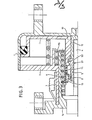
- Fig I shows a brake cylinder apparatus with a double-acting slack adjuster mechanism according to the invention in a longitudinal, partly cross-sectional view of one half thereof
- Fig 2 in the same manner shows a single-acting embodiment of such a slack adjuster mechanism
- Fig 3 also in the same manner shows an embodiment of such a slack adjuster mechanism, which is double-acting in operation and single-acting at rest.
- a brake cylinder apparatus and slack adjuster mechanism according to the invention are combined in a short apparatus comprising, apart from a cylinder 1 with its lid 2 and a piston 3 within the cylinder, a concentric arrangement of elements from the center and outwards.
- the concentric arrangement from the center and outwards comprises a short non-rotary threaded adjusting rod 4, an adjusting nut 5, a storage spring 6, a guiding tube 7, and a compression spring 15.
- the concentric arrangement from the center and outwards comprises a short non-rotary threaded adjusting rod 4, an adjusting nut 5, a storage spring 6, a guiding tube 7, and a compression spring 15.
- the nut 5 fulfils both the adjusting function by adjusting the length of the apparatus in its central portion and the function of permitting the apparatus to be length adjusted at its concentric part.
- the contacting surfaces Sl and S2 providing both functions are therefore superposed in diameter instead of being disposed longitudinally as in known apparatuses.
- the compression spring 15 permits to retain the nut 5 when there is no effective development of the braking force. It is compressed during the elastic travel.
- the nut 5 according to the invention replaces the rotary adjusting rod and the adjuster nut of such known devices in which screwing or unscrewing of said rotary adjusting rod within said adjuster nut causes the apparatus to become shorter or longer.
- the rotary nut 5 of the invention which is the only rotary part in the apparatus, makes it unnecessary to provide a bearing as required by a rotary rod. Since there is no bearing the length of the apparatus is smaller.
- this invention also ensures a simpler guiding of the piston 3, reduces friction and facilitates taking up slack.
- the apparatus according to the invention is simpler and its realization implies less expenses while being more reliable.
- the apparatus comprises a ball abutment 8 and a retaining spring 9 (Fig 2).
- the apparatus comprises a single ball abutment 8 with a cup 10 or a ball bearing (not shown) and a spring 11 (Fig 1).
- the apparatus in its embodiment which is double-acting in operation and single-acting at rest the apparatus according to the invention comprises a cuplike abutment 12 preventing declutching between the nut 5 and the sleeve 13, which corresponds to the locking of the adjuster mechanism at rest and the unlocking of the adjuster mechanism at braking (Fig 3).
- the apparatus comprises a rotary head 14 for screwing and unscrewing the adjuster mechanism.
Landscapes
- Engineering & Computer Science (AREA)
- Mechanical Engineering (AREA)
- General Engineering & Computer Science (AREA)
- Braking Arrangements (AREA)
Applications Claiming Priority (2)
| Application Number | Priority Date | Filing Date | Title |
|---|---|---|---|
| FR8409888 | 1984-06-22 | ||
| FR8409888A FR2566494B1 (fr) | 1984-06-22 | 1984-06-22 | Appareil a cylindre de frein et mecanisme de regleur de jeu notamment pour vehicules ferroviaires |
Publications (2)
| Publication Number | Publication Date |
|---|---|
| EP0165641A1 true EP0165641A1 (fr) | 1985-12-27 |
| EP0165641B1 EP0165641B1 (fr) | 1988-09-28 |
Family
ID=9305354
Family Applications (1)
| Application Number | Title | Priority Date | Filing Date |
|---|---|---|---|
| EP85200942A Expired EP0165641B1 (fr) | 1984-06-22 | 1985-06-14 | Appareil à cylindre de frein et mécanisme de régleur de jeu, notamment pour véhicules ferroviaires |
Country Status (5)
| Country | Link |
|---|---|
| EP (1) | EP0165641B1 (fr) |
| KR (1) | KR860000180A (fr) |
| BR (1) | BR8502981A (fr) |
| DE (1) | DE3565303D1 (fr) |
| FR (1) | FR2566494B1 (fr) |
Cited By (4)
| Publication number | Priority date | Publication date | Assignee | Title |
|---|---|---|---|---|
| WO2010043325A1 (fr) * | 2008-10-15 | 2010-04-22 | Knorr-Bremse Systeme für Schienenfahrzeuge GmbH | Cylindre de frein pneumatique |
| CN103335040A (zh) * | 2013-07-17 | 2013-10-02 | 四川制动科技股份有限公司 | 一种铁道车辆用单元制动缸 |
| WO2017084617A1 (fr) * | 2015-11-20 | 2017-05-26 | 中车戚墅堰机车车辆工艺研究所有限公司 | Vérin et dispositif de serrage de frein le comprenant |
| CN113120764A (zh) * | 2020-01-15 | 2021-07-16 | 宝山钢铁股份有限公司 | 一种起重机械制动器行程监测预警及自动调整装置 |
Citations (6)
| Publication number | Priority date | Publication date | Assignee | Title |
|---|---|---|---|---|
| US3744596A (en) * | 1971-01-12 | 1973-07-10 | Bromsregulator Svenska Ab | Pneumatic cylinder-piston unit for railway brake riggings |
| FR2276204A1 (fr) * | 1974-06-24 | 1976-01-23 | Bromsregulator Svenska Ab | Dispositif permettant de rentrer le poussoir d'un frein commande par pression fluidique et comportant un regleur a simple effet |
| US4036332A (en) * | 1975-07-14 | 1977-07-19 | Svenska Aktiebolaget Bromsregulator | Slack adjuster built into a brake unit for a rail vehicle brake system |
| US4138002A (en) * | 1977-02-09 | 1979-02-06 | Sab Industri Ab | Slack adjuster for a rail vehicle brake system |
| DE2830361B1 (de) * | 1978-07-11 | 1980-01-03 | Knorr Bremse Gmbh | Selbsttaetige Nachstellvorrichtung fuer Bremsgestaenge,insbesondere Bremszylinder,von Fahrzeugen,insbesondere Schienenfahrzeugen |
| FR2500897A1 (fr) * | 1981-03-02 | 1982-09-03 | Sab | Perfectionnements apportes aux regleurs de freins |
-
1984
- 1984-06-22 FR FR8409888A patent/FR2566494B1/fr not_active Expired
-
1985
- 1985-06-14 EP EP85200942A patent/EP0165641B1/fr not_active Expired
- 1985-06-14 DE DE8585200942T patent/DE3565303D1/de not_active Expired
- 1985-06-21 BR BR8502981A patent/BR8502981A/pt not_active IP Right Cessation
- 1985-06-21 KR KR1019850004402A patent/KR860000180A/ko not_active Ceased
Patent Citations (6)
| Publication number | Priority date | Publication date | Assignee | Title |
|---|---|---|---|---|
| US3744596A (en) * | 1971-01-12 | 1973-07-10 | Bromsregulator Svenska Ab | Pneumatic cylinder-piston unit for railway brake riggings |
| FR2276204A1 (fr) * | 1974-06-24 | 1976-01-23 | Bromsregulator Svenska Ab | Dispositif permettant de rentrer le poussoir d'un frein commande par pression fluidique et comportant un regleur a simple effet |
| US4036332A (en) * | 1975-07-14 | 1977-07-19 | Svenska Aktiebolaget Bromsregulator | Slack adjuster built into a brake unit for a rail vehicle brake system |
| US4138002A (en) * | 1977-02-09 | 1979-02-06 | Sab Industri Ab | Slack adjuster for a rail vehicle brake system |
| DE2830361B1 (de) * | 1978-07-11 | 1980-01-03 | Knorr Bremse Gmbh | Selbsttaetige Nachstellvorrichtung fuer Bremsgestaenge,insbesondere Bremszylinder,von Fahrzeugen,insbesondere Schienenfahrzeugen |
| FR2500897A1 (fr) * | 1981-03-02 | 1982-09-03 | Sab | Perfectionnements apportes aux regleurs de freins |
Cited By (10)
| Publication number | Priority date | Publication date | Assignee | Title |
|---|---|---|---|---|
| WO2010043325A1 (fr) * | 2008-10-15 | 2010-04-22 | Knorr-Bremse Systeme für Schienenfahrzeuge GmbH | Cylindre de frein pneumatique |
| CN102186707A (zh) * | 2008-10-15 | 2011-09-14 | 克诺尔-布里姆斯轨道车辆系统有限公司 | 气动制动缸 |
| CN102186707B (zh) * | 2008-10-15 | 2013-12-18 | 克诺尔-布里姆斯轨道车辆系统有限公司 | 气动制动缸 |
| US8776960B2 (en) | 2008-10-15 | 2014-07-15 | Knorr-Bremse Systeme Fur Schienenfahrzeuge Gmbh | Pneumatic brake cylinder |
| CN103335040A (zh) * | 2013-07-17 | 2013-10-02 | 四川制动科技股份有限公司 | 一种铁道车辆用单元制动缸 |
| CN103335040B (zh) * | 2013-07-17 | 2015-09-09 | 四川制动科技股份有限公司 | 一种铁道车辆用单元制动缸 |
| WO2017084617A1 (fr) * | 2015-11-20 | 2017-05-26 | 中车戚墅堰机车车辆工艺研究所有限公司 | Vérin et dispositif de serrage de frein le comprenant |
| CN108474429A (zh) * | 2015-11-20 | 2018-08-31 | 中车戚墅堰机车车辆工艺研究所有限公司 | 油缸以及包括该油缸的制动夹钳装置 |
| CN108474429B (zh) * | 2015-11-20 | 2019-10-25 | 中车戚墅堰机车车辆工艺研究所有限公司 | 油缸以及包括该油缸的制动夹钳装置 |
| CN113120764A (zh) * | 2020-01-15 | 2021-07-16 | 宝山钢铁股份有限公司 | 一种起重机械制动器行程监测预警及自动调整装置 |
Also Published As
| Publication number | Publication date |
|---|---|
| DE3565303D1 (en) | 1988-11-03 |
| BR8502981A (pt) | 1986-03-04 |
| FR2566494B1 (fr) | 1986-10-24 |
| EP0165641B1 (fr) | 1988-09-28 |
| FR2566494A1 (fr) | 1985-12-27 |
| KR860000180A (ko) | 1986-01-27 |
Similar Documents
| Publication | Publication Date | Title |
|---|---|---|
| US7802662B2 (en) | Slack adjuster for railway vehicle brake rigging | |
| EP0730107A2 (fr) | Frein à disque | |
| JPH0792110B2 (ja) | 鉄道車両用ブレーキすきま調節器組立体 | |
| JPS5986727A (ja) | スポツト型デイスクブレ−キ | |
| JPS61175330A (ja) | レール車両用デイスクブレーキのためのブレーキリンク機構 | |
| DE69408945T2 (de) | Fahrpedalanordnung | |
| GB971799A (en) | Brake | |
| DE3508039A1 (de) | Innen umgriffene scheibenbremse, insbesondere fuer kraftfahrzeuge | |
| AT392524B (de) | Gleitsattel-scheibenbremse | |
| DE1750176B1 (de) | Selbsttaetig und stufenlos wirkende mechanische nachstell vorrichtung fuer eine teilbelagscheibenbremse insbeson dere fuer kraftfahrzeuge | |
| EP0165641B1 (fr) | Appareil à cylindre de frein et mécanisme de régleur de jeu, notamment pour véhicules ferroviaires | |
| US4088205A (en) | Brake cylinder with built-in slack adjuster, including means for manually resetting piston travel | |
| EP0243114B1 (fr) | Freins à disque | |
| US4537293A (en) | Hydraulic cylinder assemblies | |
| DE2546402A1 (de) | Fahrzeug-bremsbetaetigungsvorrichtung | |
| CA1237680A (fr) | Frein de secours a desserrage manuel | |
| US6386339B1 (en) | Automatic adjuster for spring applied mechanisms | |
| EP0105977B1 (fr) | Dispositif automatique de rattrapage de jeu pour freins | |
| EP0259641B1 (fr) | Dispositif à vis et à écrou à frein pour la rotation | |
| DE3621712A1 (de) | Nachstellvorrichtung fuer eine scheibenbremse, insbesondere fuer kraftfahrzeuge | |
| JPS59110928A (ja) | ブレ−キ自動調節装置 | |
| US4867283A (en) | Ramp/roller slack adjuster | |
| US4543851A (en) | Torque application assembly for closure valve of a railroad hopper car outlet | |
| DE1959081A1 (de) | Handbetaetigbare Feststellbremse | |
| DE2558581A1 (de) | Zangenscheibenbremse mit hohem drehmoment |
Legal Events
| Date | Code | Title | Description |
|---|---|---|---|
| PUAI | Public reference made under article 153(3) epc to a published international application that has entered the european phase |
Free format text: ORIGINAL CODE: 0009012 |
|
| AK | Designated contracting states |
Designated state(s): DE FR GB IT |
|
| 17P | Request for examination filed |
Effective date: 19860512 |
|
| 17Q | First examination report despatched |
Effective date: 19870724 |
|
| ITF | It: translation for a ep patent filed | ||
| GRAA | (expected) grant |
Free format text: ORIGINAL CODE: 0009210 |
|
| AK | Designated contracting states |
Kind code of ref document: B1 Designated state(s): DE FR GB IT |
|
| REF | Corresponds to: |
Ref document number: 3565303 Country of ref document: DE Date of ref document: 19881103 |
|
| ET | Fr: translation filed | ||
| PLBI | Opposition filed |
Free format text: ORIGINAL CODE: 0009260 |
|
| 26 | Opposition filed |
Opponent name: KNORR-BREMSE AG Effective date: 19890518 |
|
| PGFP | Annual fee paid to national office [announced via postgrant information from national office to epo] |
Ref country code: FR Payment date: 19900530 Year of fee payment: 6 |
|
| PGFP | Annual fee paid to national office [announced via postgrant information from national office to epo] |
Ref country code: GB Payment date: 19900608 Year of fee payment: 6 |
|
| ITTA | It: last paid annual fee | ||
| PGFP | Annual fee paid to national office [announced via postgrant information from national office to epo] |
Ref country code: DE Payment date: 19900816 Year of fee payment: 6 |
|
| RDAG | Patent revoked |
Free format text: ORIGINAL CODE: 0009271 |
|
| STAA | Information on the status of an ep patent application or granted ep patent |
Free format text: STATUS: PATENT REVOKED |
|
| 27W | Patent revoked |
Effective date: 19901004 |
|
| GBPR | Gb: patent revoked under art. 102 of the ep convention designating the uk as contracting state | ||
| ITPR | It: changes in ownership of a european patent |
Owner name: CESSIONE;SAB WABCO HOLDINGS BV |