EP0166300A2 - Récepteur pour un système de navigation par satellite du type GPS et méthode pour déterminer la position d'une station stationnaire utilisant ce récepteur - Google Patents
Récepteur pour un système de navigation par satellite du type GPS et méthode pour déterminer la position d'une station stationnaire utilisant ce récepteur Download PDFInfo
- Publication number
- EP0166300A2 EP0166300A2 EP85107188A EP85107188A EP0166300A2 EP 0166300 A2 EP0166300 A2 EP 0166300A2 EP 85107188 A EP85107188 A EP 85107188A EP 85107188 A EP85107188 A EP 85107188A EP 0166300 A2 EP0166300 A2 EP 0166300A2
- Authority
- EP
- European Patent Office
- Prior art keywords
- satellites
- station
- receiver
- signal
- satellite
- Prior art date
- Legal status (The legal status is an assumption and is not a legal conclusion. Google has not performed a legal analysis and makes no representation as to the accuracy of the status listed.)
- Withdrawn
Links
Images

Classifications
-
- G—PHYSICS
- G01—MEASURING; TESTING
- G01S—RADIO DIRECTION-FINDING; RADIO NAVIGATION; DETERMINING DISTANCE OR VELOCITY BY USE OF RADIO WAVES; LOCATING OR PRESENCE-DETECTING BY USE OF THE REFLECTION OR RERADIATION OF RADIO WAVES; ANALOGOUS ARRANGEMENTS USING OTHER WAVES
- G01S19/00—Satellite radio beacon positioning systems; Determining position, velocity or attitude using signals transmitted by such systems
- G01S19/38—Determining a navigation solution using signals transmitted by a satellite radio beacon positioning system
- G01S19/39—Determining a navigation solution using signals transmitted by a satellite radio beacon positioning system the satellite radio beacon positioning system transmitting time-stamped messages, e.g. GPS [Global Positioning System], GLONASS [Global Orbiting Navigation Satellite System] or GALILEO
- G01S19/42—Determining position
Definitions
- the present invention relates generally to a receiver for a navigation system utilizing satellites or other spacecraft, the so-called Global Positioning System (GPS) or NAVSTAR. More specifically, the invention relates to a receiver which is designed for use with GPS in determining the position of a stationary station without being affected by error in clocks on the satellite and/or in the receiver.
- GPS Global Positioning System
- NAVSTAR NAVSTAR
- GPS or NAVSTAR presently under development, will enable precise positioning anywhere on the Earth by means of a network of 18 satellites when it is completed.
- Each satellite is designed to transmit pseudo-random ranging signals from which users with receivers will obtain three-dimensional location, velocity and timing information anywhere on or near the surface of the Earth.
- Position determination utilizing GPS or NAVSTAR has been disclosed in the United State Patent 4,114,155, issued on September 12, 1978, to Raab, among others.
- the disclosed apparatus and method are intended to enable positioning of a receiver on the basis of a plurality of pseudo-random data sequences from a plurality of sources of known position.
- the disclosed invention is also intended to improve the precision of the determined position of a receiver to within 300 meters.
- Arithmetic deviation of the position of a receiver station is well provided for in GPS.
- a three-dimensional Cartesian coordinate system with its origin at the center of the Earth is used.
- the position of the receiver station can be represented as P(x, y, z).
- the distance D i between any satellite and the receiver station can be derived from the following equation:
- the distance D i between the satellite at the coordinate position P i (x i , yi, zi) and the receiver station can be measured directly in terms of the propagation delay time T i of electromagnetic signals between the satellite and the receiver station, as follow: where c is the speed of light.
- the propagation delay time T i can be derived by reference to an epoch signal which is broadcast by each satellite every 6 sec. starting at 00:00:00 every Sunday. By comparing the clock time measured by a clock in the receiver with the broadcast epoch, the delay time T i can be read directly. However, since the receiver clock will have some finite epoch error, the actual propagation delay time T i must be corrected for the error t of the receiver clock. Therefore, the actual propagation delay time T . can be derived from the following equation: where T mi is the propagation delay time derived from the difference between the satellite epoch and the receiver epoch; and t is epoch error in the receiver clock.
- Equation (3) can be modified as follows: Equation (4) includes the four unknowns x, y, z and t. Therefore, by establishing a system of four equations (4) for four signals from four different satellite, the position of the receiver station P(x, y, z) can be obtained.
- the position of the receiver can be derived by arithmetic operation on the data contained in the signal transmitted from satellites.
- the position of the satellite resulting from these arithmetic operations will have some error.
- the measurement of the propagation delay time is performed with a resolution of 20 nsec. Therefore, the resultant position of the receiver station cannot be perfectly accurate. In order to minimize the error in the resultant position of the receiver station, it would be better to have more than four equations involving more than four signals from different satellites.
- Another and more specific object of the invention is to provide a GPS receiver which obviates the effect of epoch errors in clocks on satellites and in the receiver to enable use of data sampled at different times.
- a GPS receiver sets up an equation based on known position data and propagation delay time data transmitted from two satellites and received simultaneously, and independent of time epoch errors in the clocks of the satellites and the receiver.
- the receiver accumulates equations as data is received.
- the position of the receiver station can then be derived from the accumulated equations.
- the GPS receiver is provided with a timer which is reset at the timing of transmission of the epoch signals from satellites so as to measure the signal propagation interval by latching the timer value upon receipt of each satellite signal.
- the receiver uses the following equations: where X 1j' y 1j , z 1j are known coordinates of a first satellite;
- This procedure cancels the effect of epoch errors between the satellites and the receiver by employing only known position data and the difference between the propagation intervals of two satellites, thus eliminating time-dependent errors. In addition, only two satellites are needed to set up the complete system.
- a system for determining the position of a stationary receiver station designed to receive signals from any or all of a plurality of satellites, the satellite signals encoded with data indicative of its position and of transmission timing of the signal
- the system comprises first means, in the station, for receiving the signals transmitted from at least two of the satellites, second means for deriving the position data from the signals transmitted by the received satellite, third means for deriving the apparent distance between the station and each of the sattelites on the basis of the timing of reception of the encoded transmission timing data, fourth means, active when a predetermined reception condition is satisfied, for establishing at least one equation in the unknown positional coordinates of the station including the position data and the difference between the apparent distances to at least two satellites transmitted at the same time, fifth means for storing equations established by the fourth means, sixth means for deriving the positional coordinates of the station by solving the accumulated equations, and seventh means for displaying the derived positional coordinates of the station on a display.
- the fourth means has a timer measuring the intervals between the moments of reception of signals transmitted by different satellites.
- the system includes a plurality of channels in the station, each of which is adapted to process data encoded in the signal transmitted by one corresponding satellite, each of the channels including a second means and a third means.
- Each of the channels further comprises eighth means for synchronizing operation of the channel with the signal from the corresponding satellite.
- the fourth means becomes active when at least two channels are synchronized with the signals from corresponding satellites.
- a system for determining the position of a stationary receiver station utilizing a global positioning system in which a plurality of orbitting satellites each transmit a signal encoded with data indicative of its position and of the transmission timing of the signal comprises an antenna means, disposed in the station, for receiving the signal transmitted by the satellites, a receiver means having a plurality of channels, each adapted to derive the position of a corresponding satellite from the signal transmitted by the corresponding satellite and the apparent distance between the station and the corresponding satellite on the basis of the reception timing of the signal, the receiver means responding to a predetermined receiving condition by establishing at least one equation in the unknown positional coordinates of the station and including the positions of and the difference between the distances to at least two satellites derived from signals transmitted at the same time, the receiver further including a memory means for storing the equations and an arithmetic means for deriving the positional coordinates of the station by solving the accumulated equations, and a display means for displaying the derived positional coordinates of
- a method for determining the position of a stationary station comprising the steps of:
- the interval between reception of signals from two different satellites is measured to derive the difference between the distances to those two satellites.
- the method includes a step of providing a plurality of channels in the station, each of which is adapted to process data encoded in the signal transmitted by one corresponding satellites.
- the method further comprises a step of synchronizing each of the channels with the signal from the corresponding satellite.
- the fourth step is performed when at least two channels are synchronized with the signals from corresponding satellites.
- the preferred embodiment of a GPS receiver generally comprises an antenna section 10, a main section 20 and a display section 50.
- Each of a plurality of satellites (not shown) is adapted to transmits a spectrum diffusion signal at a frequency 1575.42 MHz encoded with its own known position and with transmission timing indicative data.
- Spectrum diffusion is performed by means of a C/A mode pseudo-random-noise (PRN) signal employing a 1023-bit gold code.
- PRN pseudo-random-noise
- the antenna section 10 comprises an antenna 11 and a low-noise converter (LNC) 12.
- the antenna 11 has hemispherical directivity for receiving the spectrum diffusion signals S 1 from the satellites.
- the LNC 12 converts the spectrum diffusion signal S 1 into a signal S 2 with a first intermediate frequency of 75.42 MHz.
- the LNC 12 sends the converted signal S 2 to the main section 20 through a coaxial cable 13.
- the main section 20 has a filter 21, an amplifier 22 and a mixer 23.
- the first intermediate frequency signal S 2 from the LNC 12 is sent to the mixer 23 through the filter 21 and the amplifier 22.
- the mixer 23 is also connected to a local oscillator 24 which produces a local frequency S 4 of 64.72 MHz.
- the mixer 23 converts the first intermediate frequency signal S 2 into a second intermediate frequency signal S 4 of 10.7 M Hz by mixing the first intermediate frequency signal with the local oscillation signal S 3 from the local oscillator 24.
- the mixer 23 feeds the second intermediate frequency signal S 4 to all four channels 35, 36, 37 and 38 of a data sampling circuit.
- Each of the data sampling channels 35, 36, 37 and 38 serves as a data processing section for picking out the known position data and the propagation delay time data.
- a BPSK circuit 25 built into each channel receives the second intermediate frequency signal S 4 from the mixer 23.
- the BPSK circuit 25 is also connected to a PRN signal generator 26 to receive a false signal S s in the form of a PRN signal. Utilizing the false signal from the PN signal generator 26, the BPSK circuit 25 translates the second intermediate frequency signal S 4 to a phase-shift keying (BPSK) signal S 6 ,
- BPSK phase-shift keying
- the BPSK signal S 6 is sent through a filter 27 which has a pass-band at 10 MHz to a mixer 28.
- the mixer 28 converts the BPSK signal S 6 into a third intermediate frequency signal S 7 at 455 MHz.
- the mixer 28 is connected to an oscillator 29.
- the oscillator 29 is in particular a voltage-controlled oscillator producing a local oscillation signal centered at 10.245 MHz.
- the central frequency of the local oscillation frequency is variable over a range of ⁇ 5 MHz.
- the central frequency of the voltage-controlled oscillator 29 is controlled by a voltage control signal S 9 from CPU 30.
- the CPU derives the voltage control signal S 9 so that the third intermediate frequency is corrected based on the Doppler frequency of the satellite so as to cancel out the Doppler shift.
- the third intermediate frequency signal S 7 is sent to a data demodulation circuit 31 and also to an envelope detecting circuit 32.
- the envelope detecting circuit 32 detects the envelope of the third intermediate frequency signal s 7 for use in synchronizing the first intermediate frequency signal S 4 from the antenna section 10 and the false signal S 5 from the PN signal generator 26.
- the envelope detecting circuit 32 derives a synchronization control signal S 8 for a voltage-controlled oscillator 33.
- the envelope detecting circuit 32 controls the voltage-controlled oscillator 33 through CPU 30.
- the data demodulation circuit 31 demodulates data including position data of the satellite from the BPSK signal S 7 .
- the data demodulation circuit 31 sends the data derived from the BPSK signal to CPU 30.
- CPU 30 derives the control signal S 9 from the data input from the data demodulation circuit 31 and sends the control signal to the voltage-controlled oscillator 29 to correct for Doppler shift. Therefore, the voltage-controlled oscillator 29, the mixer 28, the data demodulating circuit 31 and CPU 30 form a feedback loop for Doppler shift correction.
- CPU 30 is also connected to a ranging circuit 34 which is adapted to derive the propagration delay time data on the basis of PRN epoch in the signal transmitted from the satellite.
- CPU 30 issues a timing signal S 10 to start an internal timer (not clearly shown) at a given timing.
- the ranging circuit 34 receives the PRN epoch and derives the propagration delay time data on the basis of the timer value upon receipt of the PRN epoch.
- the ranging circuit 34 outputs the propagration delay time data to CPU 30.
- CPU receives thus receives known position data and propagation delay time data from each of the spectrum back-diffusion circuits 35, 36, 37 and 38. Based on the known position data and the propagation delay time data received at the same time from different satellites, the CPU sets up an equation with the receiver position coordinates (x, y, z) as unknowns.
- CPU 30 has a memory 40 which stores or accumulates the equations thus established.
- CPU 30 also performs arithmetic operations on all of the accumulated expressions to derive the position of the receiver station.
- the resultant value indicative of coordinate of the position of the stationary station in the three dimensional coordinates taking the center of the Earth as the center is translated into longitude, latitude and altitude.
- the data indicative of the determined position data in a form of longitude, latitude and altitude and/or in a form of aforementioned coordinate, is displayed on the display 50.
- the display 50 includes a display screen 50a and a mode selector 50b which is adapted to select one of the form of data to be displayed on the display screen.
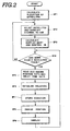
- the elevations of the various satellites over the horizon are derived in per se well known manner on the basis of the previously stored data in the internal memory, at a step SP 1 .
- the elevation of each satellite derived at the step SP 1 is compared with a predetermined threshold i.e. 5°, at a step SP 2 .
- CPU 30 allocates one of the data sampling channels 35, 36, 37 and 38 to each satellite from which signal S 1 can be received, i.e. with an elevation >5°.
- the PRN signal generator 26 of each channel 35, 36, 37 and 38 generates a false signal with a unique value indicative of the corresponding satellite.
- the Doppler shift of each selected satellite is calculated and the control signal S 9 is produced.
- the control signal S 9 controls the voltage controlled oscillator 29 so as to eliminate Doppler shift from the third intermediate frequency signal S 7 .
- the CPU checks to ensure that at least two channels of the data sampling channels 35, 36, 37 and 38 are synchronized with the signals transmitted by corresponding satellites. If fewer than two channels are in use, in other words, if fewer than two satellites are being tracked, the loop comprising steps SO 2 , SP 3 and SP 4 is repeated until at least two satellites are being tracked. After at least two satellites are found, the known position data (xij, y ij , z ij ) of the satellites is separated by the data demodulation circuit 31 and the propagation delay time data is derived by the ranging circuit 34 at a step SP 5 .
- CPU 30 Based on the position data and the propagation delay time data, CPU 30 establishes equations related to each satellite separately, at a step SP 6 . Assuming three satellites are being tracked and the positional coordinates of the satellites are (x 1j , y 1j , z 1j ), (x 2 j, Y 2j , z 2j ) and (x 3j , Y 3j , z 3 j ) and the propagation delay times are respectively T 1 j , T 2j and T 3 j , the following three equations are established: where t j is a constant indicative of epoch error between the clocks in the satellite and the clock in the receiver.
- the factor of the epoch error is eliminated from the equations (8) and (9). Since the epoch error is only the time-dependent unknown, the receiver station position can be derived from a system of equations employing values sampled at different times. Therefore, even if the number of equations that can be established at a given timing is less than that required to solve the equations for all unknowns, it is possible to solve for the positional unknowns by utilizing equations established at different times.
- the equations established at the step SP 6 are transferred to the memory 40 at a step SP 7 for storage until enough equations are established. Thereafter, all of the equations stored in the memory 40 are read out at a step SPg. Then, the equations are all processed at the step SP 8 to derive the position of the receiver station. In practice, the method of least squares can be used to minimize error.
- the derived Cartesian coordinates (x, y, z) of the receiver position can then be transformed into longitude, latitude and altitude values for the receiver station at the step SP 8 .
- the final position data, i.e. longitude, latitude and altitude of the receiver position thus derived are then displayed on the display unit 50 at a step SP 9 .
- step SP 9 the process goes back to the step SP 4 again to ensure that at least two satellites are being tracked. If not, the loop of the steps SP 2 , SP 3 and SP 4 is repeated until at least two satellites are found whereupon the steps SP to SP 9 are again executed for the next epoch signal transmission.
- the position of the stationary station can be determined by utilizing at least two orbiting satellites.
- the GPS receiver In the specific embodiment of the GPS receiver, four data sampling channels are provided so that the receiver can receive signals from different four satellites at the same time.
- the number of channels is not intended to limit the specific number. Only the essential feature is that the receiver is provided with two or more channels to receive at least two signals from different two satellites. Therefore, the invention should be understood to include any possible embodiments and/or modifications of the embodiments to be embodied without departing from the principle of the invention.
Landscapes
- Engineering & Computer Science (AREA)
- Radar, Positioning & Navigation (AREA)
- Remote Sensing (AREA)
- Computer Networks & Wireless Communication (AREA)
- Physics & Mathematics (AREA)
- General Physics & Mathematics (AREA)
- Position Fixing By Use Of Radio Waves (AREA)
- Navigation (AREA)
Applications Claiming Priority (2)
| Application Number | Priority Date | Filing Date | Title |
|---|---|---|---|
| JP121091/84 | 1984-06-13 | ||
| JP12109184A JPS61770A (ja) | 1984-06-13 | 1984-06-13 | Gps受信機 |
Publications (2)
| Publication Number | Publication Date |
|---|---|
| EP0166300A2 true EP0166300A2 (fr) | 1986-01-02 |
| EP0166300A3 EP0166300A3 (fr) | 1987-07-29 |
Family
ID=14802648
Family Applications (1)
| Application Number | Title | Priority Date | Filing Date |
|---|---|---|---|
| EP85107188A Withdrawn EP0166300A3 (fr) | 1984-06-13 | 1985-06-11 | Récepteur pour un système de navigation par satellite du type GPS et méthode pour déterminer la position d'une station stationnaire utilisant ce récepteur |
Country Status (4)
| Country | Link |
|---|---|
| EP (1) | EP0166300A3 (fr) |
| JP (1) | JPS61770A (fr) |
| AU (1) | AU4364785A (fr) |
| CA (1) | CA1241414A (fr) |
Cited By (10)
| Publication number | Priority date | Publication date | Assignee | Title |
|---|---|---|---|---|
| EP0353849A1 (fr) * | 1988-06-22 | 1990-02-07 | Hitachi, Ltd. | Procédé de réception d'un signal pour un appareil d'utilisateur dans un système GPS |
| DE3925831A1 (de) * | 1989-08-04 | 1991-02-07 | Bosch Gmbh Robert | Kraftfahrzeugsteuer- oder regelungssystem |
| EP0552975A3 (en) * | 1992-01-24 | 1994-05-25 | Novatel Communications Ltd | A pseudorandom noise ranging receiver which compensates for multipath distortion by dynamically adjusting the time delay spacing between early and late correlators |
| US5495499A (en) * | 1990-11-28 | 1996-02-27 | Novatel Communications, Ltd. | Pseudorandom noise ranging receiver which compensates for multipath distortion by dynamically adjusting the time delay spacing between early and late correlators |
| WO1998039667A1 (fr) * | 1997-03-05 | 1998-09-11 | Koninklijke Philips Electronics N.V. | Procede et recepteur de navigation par satellite pour determiner un lieu geographique |
| US5815539A (en) * | 1992-01-22 | 1998-09-29 | Trimble Navigation Limited | Signal timing synchronizer |
| US6417800B1 (en) | 2000-01-04 | 2002-07-09 | Nokia Mobile Phones Ltd. | Method for determining reference time error and an electronic device |
| US6570533B2 (en) | 2000-05-30 | 2003-05-27 | Nokia Mobile Phones Ltd. | Method for determining the phase of information, and an electronic device |
| US6618006B1 (en) | 2001-02-05 | 2003-09-09 | Nokia Corporation | Method for defining the error of reference time and an electronic device |
| EP4307013A1 (fr) * | 2022-07-11 | 2024-01-17 | u-blox AG | Positionnement statique gnss |
Families Citing this family (5)
| Publication number | Priority date | Publication date | Assignee | Title |
|---|---|---|---|---|
| JPH0656411B2 (ja) * | 1984-12-27 | 1994-07-27 | ソニー株式会社 | スペクトラム拡散信号受信装置 |
| US4734702A (en) * | 1986-02-25 | 1988-03-29 | Litton Systems, Inc. | Passive ranging method and apparatus |
| AU634587B2 (en) * | 1989-10-11 | 1993-02-25 | Sigtec Navigation Pty Ltd | Position reporting system |
| JPH042206A (ja) * | 1990-04-19 | 1992-01-07 | Nec Corp | 車載型衛星通信装置 |
| CN110068323B (zh) * | 2019-05-15 | 2021-02-02 | 北京邮电大学 | 网络时延定位误差补偿方法、装置及电子设备 |
Family Cites Families (2)
| Publication number | Priority date | Publication date | Assignee | Title |
|---|---|---|---|---|
| US3384891A (en) * | 1965-02-11 | 1968-05-21 | Gen Electric | Method and system for long distance navigation and communication |
| US4114155A (en) * | 1976-07-30 | 1978-09-12 | Cincinnati Electronics Corporation | Position determining apparatus and method |
-
1984
- 1984-06-13 JP JP12109184A patent/JPS61770A/ja active Pending
-
1985
- 1985-06-11 EP EP85107188A patent/EP0166300A3/fr not_active Withdrawn
- 1985-06-12 CA CA000483802A patent/CA1241414A/fr not_active Expired
- 1985-06-13 AU AU43647/85A patent/AU4364785A/en not_active Abandoned
Cited By (12)
| Publication number | Priority date | Publication date | Assignee | Title |
|---|---|---|---|---|
| EP0353849A1 (fr) * | 1988-06-22 | 1990-02-07 | Hitachi, Ltd. | Procédé de réception d'un signal pour un appareil d'utilisateur dans un système GPS |
| DE3925831A1 (de) * | 1989-08-04 | 1991-02-07 | Bosch Gmbh Robert | Kraftfahrzeugsteuer- oder regelungssystem |
| US5495499A (en) * | 1990-11-28 | 1996-02-27 | Novatel Communications, Ltd. | Pseudorandom noise ranging receiver which compensates for multipath distortion by dynamically adjusting the time delay spacing between early and late correlators |
| US5809064A (en) * | 1990-11-28 | 1998-09-15 | Novatel, Inc. | Pseudorandom noise ranging receiver which compensates for multipath distortion by dynamically adjusting the time delay spacing between early and late correlators |
| US5815539A (en) * | 1992-01-22 | 1998-09-29 | Trimble Navigation Limited | Signal timing synchronizer |
| EP0552975A3 (en) * | 1992-01-24 | 1994-05-25 | Novatel Communications Ltd | A pseudorandom noise ranging receiver which compensates for multipath distortion by dynamically adjusting the time delay spacing between early and late correlators |
| WO1998039667A1 (fr) * | 1997-03-05 | 1998-09-11 | Koninklijke Philips Electronics N.V. | Procede et recepteur de navigation par satellite pour determiner un lieu geographique |
| US6417800B1 (en) | 2000-01-04 | 2002-07-09 | Nokia Mobile Phones Ltd. | Method for determining reference time error and an electronic device |
| US6570533B2 (en) | 2000-05-30 | 2003-05-27 | Nokia Mobile Phones Ltd. | Method for determining the phase of information, and an electronic device |
| US6618006B1 (en) | 2001-02-05 | 2003-09-09 | Nokia Corporation | Method for defining the error of reference time and an electronic device |
| EP4307013A1 (fr) * | 2022-07-11 | 2024-01-17 | u-blox AG | Positionnement statique gnss |
| US12560725B2 (en) | 2022-07-11 | 2026-02-24 | U-Blox Ag | Static GNSS positioning |
Also Published As
| Publication number | Publication date |
|---|---|
| AU4364785A (en) | 1985-12-19 |
| EP0166300A3 (fr) | 1987-07-29 |
| JPS61770A (ja) | 1986-01-06 |
| CA1241414A (fr) | 1988-08-30 |
Similar Documents
| Publication | Publication Date | Title |
|---|---|---|
| EP1057041B1 (fr) | Procede et systeme mondial autonome de localisation (gps) a haute sensibilite | |
| US5119102A (en) | Vehicle location system | |
| US7696922B2 (en) | Method and apparatus for geolocation determination | |
| KR100543634B1 (ko) | 네트워크 위치확인 시스템 형성 방법 및 장치 | |
| US6525688B2 (en) | Location-determination method and apparatus | |
| EP1275259B1 (fr) | Synchronisation temporelle d'un appareil de positionnement gps | |
| US6570533B2 (en) | Method for determining the phase of information, and an electronic device | |
| US8299961B2 (en) | Method and system for selecting optimal satellites in view | |
| US8255160B2 (en) | Integrated mobile terminal navigation | |
| CA2647555C (fr) | Systeme facilitant la determination de la position gnss dans des environnements de propagation de signal pauvres | |
| US20060282216A1 (en) | Differential GPS corrections using virtual stations | |
| US20030187575A1 (en) | Time determination in satellite positioning system receivers and methods therefor | |
| EP0166300A2 (fr) | Récepteur pour un système de navigation par satellite du type GPS et méthode pour déterminer la position d'une station stationnaire utilisant ce récepteur | |
| US6417800B1 (en) | Method for determining reference time error and an electronic device | |
| US20010033627A1 (en) | Method for performing location determination and an electronic device | |
| US20010008393A1 (en) | Method for performing positioning and an electronic device | |
| US6583759B2 (en) | Method for determining a position, a positioning system, and an electronic device | |
| EP2069817A1 (fr) | Procédé et système d'acquisition de codes de bruit pseudo-aléatoire de signal gps cohérent avec suivi de tous les satellites visibles ( all-in-view ) | |
| US20030224802A1 (en) | Locating a mobile unit | |
| US7161533B2 (en) | Method and a system for positioning, and an electronic device | |
| US6393291B1 (en) | Method and apparatus for deriving a high rate output in a GPS system | |
| EP2003469B1 (fr) | Procédé de positionnement et un dispositif électronique | |
| EP1735633B1 (fr) | Systeme et procede pour la recherche de localisation au moyen de signaux de communication | |
| Appleyard et al. | Navstar-Global Positioning System | |
| JP2005326207A (ja) | 測位方法 |
Legal Events
| Date | Code | Title | Description |
|---|---|---|---|
| PUAI | Public reference made under article 153(3) epc to a published international application that has entered the european phase |
Free format text: ORIGINAL CODE: 0009012 |
|
| AK | Designated contracting states |
Designated state(s): AT DE FR GB NL |
|
| PUAL | Search report despatched |
Free format text: ORIGINAL CODE: 0009013 |
|
| AK | Designated contracting states |
Kind code of ref document: A3 Designated state(s): AT DE FR GB NL |
|
| STAA | Information on the status of an ep patent application or granted ep patent |
Free format text: STATUS: THE APPLICATION IS DEEMED TO BE WITHDRAWN |
|
| 18D | Application deemed to be withdrawn |
Effective date: 19880130 |
|
| RIN1 | Information on inventor provided before grant (corrected) |
Inventor name: KAGEYAMA, KOJI Inventor name: KIKUCHI, ATSUSHI |