EP0166929A2 - Dispositif de contact électrique pour garde-boue de bicyclette en matériau feuilleté consistant en une matière synthétique et au moins une feuille métallique, entourée de chaque côté de cette matière synthétique - Google Patents
Dispositif de contact électrique pour garde-boue de bicyclette en matériau feuilleté consistant en une matière synthétique et au moins une feuille métallique, entourée de chaque côté de cette matière synthétique Download PDFInfo
- Publication number
- EP0166929A2 EP0166929A2 EP85105945A EP85105945A EP0166929A2 EP 0166929 A2 EP0166929 A2 EP 0166929A2 EP 85105945 A EP85105945 A EP 85105945A EP 85105945 A EP85105945 A EP 85105945A EP 0166929 A2 EP0166929 A2 EP 0166929A2
- Authority
- EP
- European Patent Office
- Prior art keywords
- extension
- contacting device
- head
- projections
- underside
- Prior art date
- Legal status (The legal status is an assumption and is not a legal conclusion. Google has not performed a legal analysis and makes no representation as to the accuracy of the status listed.)
- Granted
Links
Images


Classifications
-
- B—PERFORMING OPERATIONS; TRANSPORTING
- B62—LAND VEHICLES FOR TRAVELLING OTHERWISE THAN ON RAILS
- B62J—CYCLE SADDLES OR SEATS; AUXILIARY DEVICES OR ACCESSORIES SPECIALLY ADAPTED TO CYCLES AND NOT OTHERWISE PROVIDED FOR, e.g. ARTICLE CARRIERS OR CYCLE PROTECTORS
- B62J15/00—Mud-guards for wheels
-
- H—ELECTRICITY
- H01—ELECTRIC ELEMENTS
- H01R—ELECTRICALLY-CONDUCTIVE CONNECTIONS; STRUCTURAL ASSOCIATIONS OF A PLURALITY OF MUTUALLY-INSULATED ELECTRICAL CONNECTING ELEMENTS; COUPLING DEVICES; CURRENT COLLECTORS
- H01R4/00—Electrically-conductive connections between two or more conductive members in direct contact, i.e. touching one another; Means for effecting or maintaining such contact; Electrically-conductive connections having two or more spaced connecting locations for conductors and using contact members penetrating insulation
- H01R4/26—Connections in which at least one of the connecting parts has projections which bite into or engage the other connecting part in order to improve the contact
-
- B—PERFORMING OPERATIONS; TRANSPORTING
- B62—LAND VEHICLES FOR TRAVELLING OTHERWISE THAN ON RAILS
- B62J—CYCLE SADDLES OR SEATS; AUXILIARY DEVICES OR ACCESSORIES SPECIALLY ADAPTED TO CYCLES AND NOT OTHERWISE PROVIDED FOR, e.g. ARTICLE CARRIERS OR CYCLE PROTECTORS
- B62J6/00—Arrangement of optical signalling or lighting devices on cycles; Mounting or supporting thereof; Circuits therefor
- B62J6/01—Electric circuits
-
- H—ELECTRICITY
- H01—ELECTRIC ELEMENTS
- H01R—ELECTRICALLY-CONDUCTIVE CONNECTIONS; STRUCTURAL ASSOCIATIONS OF A PLURALITY OF MUTUALLY-INSULATED ELECTRICAL CONNECTING ELEMENTS; COUPLING DEVICES; CURRENT COLLECTORS
- H01R4/00—Electrically-conductive connections between two or more conductive members in direct contact, i.e. touching one another; Means for effecting or maintaining such contact; Electrically-conductive connections having two or more spaced connecting locations for conductors and using contact members penetrating insulation
- H01R4/06—Riveted connections
Definitions
- the invention is based on an electrical contacting device for sandwich-type wheel protectors made of plastic and at least one metal foil which is enclosed on all sides by the plastic. According to the preamble of the main claim.
- the extensions penetrating the wheel arch protector are supposed to make electrical contact with the metal foil, which is sandwiched between two plastic films or webs embedded on all sides, in order to provide a cable-free power supply for the electrical devices attached to the wheel arch protector or in the vicinity thereof, for example the Over the course of time, however, it has been found that this contacting device, which is quite advantageous per se, shows a continuously increasing contact resistance between the extensions and the metal foil of the wheel protector after prolonged use, right up to complete power interruption.
- the invention has for its object to provide an electrical contacting device for the wheel protectors described in DE-AS 16 80 844, which has a reduced contact resistance to the metal foil, which is maintained over a significantly longer period of time even under unfavorable weather conditions.
- the contacting device according to the invention is characterized by the features of the main claim.
- the contact surfaces between the extension and the metal foil provide a seal for the contact point between the extension and the metal foil through the contact surfaces of the head and the fastening device on the plastic, and corrosive influences can occur , such as moisture and salt water, are effectively kept away from the contact point.
- the large number of projections protruding from the outer circumference of the extension results in a large number of contact points between the extension and the metal foil, even if one or the other contact point between an extension and the metal foil was inadequate from the beginning or has deteriorated over time. All measures together result in a significantly higher reliability and service life of the contacting device.
- a particularly reliable electrical connection between the protrusions and the metal foil is obtained if the protrusions are sharp-edged because this can penetrate a possibly adhering and poorly conductive oxide skin on the metal foil if the contacting device is pressed into the correspondingly prepared, narrowly tolerated opening of the wheel protector becomes.
- a very large number of electrically active projections can be produced if the extension has a circular cross section at least in the region of the projections and the projections themselves are formed by knurling.
- the knurling has the further advantage that it forms an anti-rotation device for the contacting device together with the plastic layer of the wheel protector, because the teeth of the knurling also penetrate into the plastic, which has a much greater mechanical strength than the thin, generally made of aluminum existing metal foil.
- the projections can, however, also be formed by the corners of a polygon, for example a hexagon, which press into the metal foil when the extension is inserted into the prepared round opening of the wheel protector.
- This embodiment also allows the use of an original circle Round tubular extension, which is expanded polygonal afterwards by a suitable tool after mounting the contacting device in the opening of the wheel protector. In this way, carryover or smearing of plastic material into the area between the extension and the metal foil is reliably avoided.
- the projections measured in the longitudinal direction of the extension, have a length which is less than the thickness of the wheel arch protector, such that they end within the wheel protector in the assembled state.
- the seal in the area of the fastening device, i.e. on the end opposite the head of the contacting device is simplified because no seal adapted to the shape of the projections is required.
- an additional sealing device which lies between the fastening device and the surface of the wheel protector which is adjacent in the assembled state and surrounds the extension sealingly.
- a sealing device can consist of an undeformable washer with a truncated cone-shaped central opening and an elastically or plastically deformable sealing washer, which penetrates into the truncated cone-shaped central opening of the washer when the fastening device is tightened, thus sealing the gap between the extension and the plastic of the wheel protector.
- sealing device Another possibility of the sealing device consists in a bell-shaped hood which can be placed on the extension and an O-ring which is chambered between the extension and the inner cavity of the hood. These.
- the type of sealing device is particularly useful in the case of a polygonal extension.
- the tightness between the head of the contacting device and the wheel protector can be improved, in particular if the wheel protector is strongly curved, in that the underside of the head is concave.
- Another way to achieve the same goal is to provide an annular groove concentrically surrounding the extension in the underside of the head. In both cases, relatively sharp edges are formed, which press into the soft, plastic outer surface of the mudguard.
- a fastening device of the contacting device which can be carried out very easily and inexpensively at least in the factory, consists in the extension, after the contacting device has been inserted into the corresponding opening of the wheel protector, rivet if necessary with the interposition of the aforementioned sealing devices.
- the corresponding closing head forms the fastening device anchored to the extension.
- the fastening device is formed by an external thread of the extension and a nut that can be screwed onto the external thread, because a subsequent attachment is then easily possible even without the use of complex tools.
- the contacting device has a through hole which passes through the head and the extension coaxially, a plug can be used for further electrical connection, so that a screw-free electrical connection is possible.
- the Kunststoffierunqs becomes particularly inexpensive if it is made in the manner of a hollow rivet, the head of the contacting device being formed by the rivet head, which is optionally designed in accordance with the above statements.
- riveting in particular is very simple during the assembly of the contacting device, the opening for the plug being obtained at the same time.
- the resistance of the contacting device can be increased if it consists of a corrosion-resistant stainless steel.
- a corrosion-resistant stainless steel for example, made of stainless steel with the designation 4305.
- mudguards are known under the name "Chromoplastics" and their structure and method of manufacture are described in DE-AS 16 80 844, to which reference is expressly made here.
- the mudguard consists of three sandwich-like layers, namely a lower plastic layer 3 facing the actual wheel, a thin metal foil 4 above it and a further layer of plastic 5 finally located above the metal foil 4.
- the two plastic layers 3 and 5 completely enclose the metal foil 4, which is about 0.05 to 0.1 mm thick and usually consists of aluminum.
- the contacting device serves to establish an electrical connection with the metal foil 4 embedded between the plastic layers 3 and 5, so as to obtain a cable-free power supply line for the power supply line to the electrical devices attached to the wheel protector.
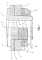
- the contacting device 1 contains a flat, disc-shaped head 6 which is circular in cross section, the underside 7 of which, facing the plastic layer 5, is concave in the manner illustrated.
- a cylindrical extension 8 protrudes in one piece from the underside 7 of the head 6 and, as shown in FIG. 1, leads through a corresponding opening 9 in the wheel protector 2 in the assembled state.
- the head 6 and the extension 8 are made of metal.
- the cylindrical extension 8 which runs coaxially and at right angles to the head 6, has on its section adjoining the underside 7 a knurled portion 11 which merges at 12 into an external thread 13 whose Au strip diameter is smaller than that in the manner shown Outside diameter of the knurling 11.
- the height of the knurling 11 is smaller than the thickness of the wheel protector 2, which is in the range between 1.5 ... 2.5 mm.
- Knurling 11 creates a large number of fine projections or teeth 14 with sharp edges on extension 8, which protrude beyond the outer circumference of extension 8 and extend through metal foil 4.
- the teeth 14 formed by the straight, simple knurling 11 run, as shown, parallel to the longitudinal axis 16 of the contacting device 1.
- the metal foil is punched 4 by the end faces of the teeth formed by the knurling 11 14 when the contacting means is inserted into the opening 9 1
- 14 form the teeth of the knurling 11 in a g to the outdoor e winch 13 adjacent area 15, which is approximately 0.1 mm high, an imaginary truncated cone, the small diameter of which corresponds to the outer diameter of the external thread 13 and the large diameter of which is equal to the outer diameter of the knurling 11.
- the outer diameter of the knurling 11 is preferably 0.1 to 0.2 mm larger than the outer diameter of the thread 13, which is approximately 4 mm.
- a nut 16 which is screwed onto the external thread 13 of the extension 8, is used to hold the contacting device 1 in the wheel protector 2, with which a washer 17 is pressed against the outside of the plastic layer 3 with the interposition of a soft, plastically or elastically deformable sealing disk 18.
- the center bore 19 of the plane-parallel insert washer 17 is tapered, its larger diameter facing the sealing washer 18 in order to effectively seal the external thread 13, which is designed as a fine thread, by penetrating the material of the sealing washer 18.
- the sealing effect can be further increased if the sealing washer 18 contains a circumferential bead 180 which is concentric with its central bore and which, as shown, projects into the conical central bore 19 of the non-deformable washer 17, which is preferably made of metal, so that even small ones
- the bead 180 is already pressed axially against the outer circumference of the extension 8 by the oblique wall of the center bore 19.
- the surface of the sealing washer 18 facing the plastic layer 3 is pre-shaped convexly.
- the contacting device 1 shown serves as a socket for a contact plug shown in FIG. 4, it contains a cylindrical through bore 21 which is coaxial with the extension 8 and completely penetrates the contacting device 1.
- the contacting device 1 is mounted on the wheel protector 2 in such a way that the opening 9 is first made on the wheel protector 2, for example by punching.
- the inside width of the opening 9 is slightly larger than the outside diameter of the thread 13, but significantly smaller than the outside diameter of the knurling 11, in order to easily insert the contacting device 1.
- the contacting device 1 can be inserted into the opening 9 prepared in this way easily insert easily until the frustoconical section 15 of the knurling 11 abuts the outer edge of the opening 9.
- the plastic layer 5 is gradually pushed aside radially with respect to the longitudinal axis 20 due to the frustoconical section 15, so that as far as possible no plastic of the plastic layer 5 from the teeth 14 of the knurling 11 is taken in the direction of the insertion movement of the contacting device 1.
- the frustoconical section 15 finally comes to the metal foil 4, which is then also gradually pushed sideways or radially with respect to the longitudinal axis 16, because the teeth 14 rise in the frustoconical Section 15 gradually from the outer diameter of the thread 13 to its full height.
- the knurling 11 still partially penetrates the lower plastic layer 3, because the axial extent of the knurling 11 is dimensioned such that its end face 12 comes to lie within the lower plastic layer 3 when the contacting device 1 is fully pressed in.
- the contacting device 1 is also pulled more firmly into the opening 9 of the wheel protector 2, as a result of which the outer edge of the concave underside 7 also lies sealingly against the outside of the plastic layer 5.
- the contact point between the extension 8 and the metal foil 4 is also sealed from the other side and no moisture or salt water can penetrate to the contact point.
- the projections or teeth 14 of the knurling 11 simultaneously prevent the extension 8 from turning in the opening 9 when the nut 16 is tightened, so that complicated tools for holding the head 6 are unnecessary.
- FIG. 2 illustrates a further exemplary embodiment of the contacting device 1, which differs from the exemplary embodiment according to FIG. 1 only in the design of the fastening device, which in the preceding case is formed by the external thread 13 and the nut 16 screwed thereon.
- the same reference numerals are therefore used for the contacting device 1 according to FIG. 2 for corresponding components which are not described again.
- the contacting device 1 in turn contains a cylindrical extension 8 which is coaxial with the head 6 and which has knurling 11 in its area adjoining the underside 7, the axial extent of which is approximately half to three-quarters of the thickness of the wheel protector 2.
- the part of the extension 8 adjoining the knurling 11 is, however, smooth-walled cylindrical, the outside diameter being smaller than the outside diameter of the knurling 11.
- the contacting device 1 is fastened by riveting the free end of the extension 8, in which the closing head 22 shown in FIG. 2 is formed.
- the closing head 22 presses the washer 17, as before, against the sealing washer 18, which thereby flows into the conical center opening 19.
- the sealing washer 18 is nevertheless expedient, because the outside of the plastic layer 3 is curved as a rule about two axes with different radii of curvature due to the shape of the wheel protector 2 , so that under certain circumstances without the sealing washer 18 leaks between the washer 17 required for riveting and the underside of the plastic layer 3 can occur.
- the extension 8 is countersunk at 23 at its end facing away from the head 6.
- the Kunststofftechnikseinrichtunq 1 consists of one Hollow or tubular rivet 30 with a rivet head 31 and an adjoining cylindrical tubular shank 32.
- the rivet head 31 relative to the shaft 32 crimped to 180 0 to the outside and thus forms including a extending around the shank 32 annular groove 33 the Head 6 of the contacting device 1, while the extension 8 consists of the shaft 32.
- the opening 21 of the contacting device 1 i.e. a mandrel with a regular polygonal cross-section, for example hexagonal, is pressed into the shaft 32 of the riveted tubular rivets 30, as a result of which projections are formed on the outside of the extension 8, which penetrate into the metal foil 4 and produce the desired electrical contact.
- a chambered O-ring 330 can also be used.
- an approximately bell-shaped hood 34 is seated between the closing head 22 and the plastic layer 3 of the wheel protector 2, which is pushed onto the extension 8 with its central opening 35 and points towards the plastic layer 3 with its edge 36 which runs approximately parallel to the extension 8 .
- a chamber is thus created between the inside of the hood 34 and the outside of the extension 8, in which the O-ring 330 is clamped in a known manner, since the height of the space delimited by the hood 34 in the axial direction is smaller than the thickness of the O- Ring 330 is.
- the O-ring 330 thereby seals against the outside of the extension 8, the outside of the plastic layer 3 and the inside wall of the hood 34, which in turn is supported with its end face on the outside of the plastic layer 3.
- the contacting device as shown in the various forms in the figures, consists of a corrosion-inhibiting or corrosion-free material, preferably stainless steel with the designation 4305.
- FIG. 4 finally shows a connector 38, also made of stainless steel, suitable for the contacting device 1, which has an upper cylindrical shaft part 41 provided with a blind bore 39 as well as a connector part 42 integrally molded coaxially therewith, also with a circular cross section.
- the cylindrical plug part 42 has a circumferential bead 43 at its end facing away from the shaft part 41 and is slotted lengthwise at 44.
- the slot 44 runs through the longitudinal axis of the plug 38 and allows the resulting jaws 45 and 46 to spring together when the.
- Bead 43 penetrates into the opening 21 of the contacting device 1.
- a softer spring effect is achieved if the plug part 42 is provided with a taper 47 in the area between the bead 43 and the sheep part 41, as indicated by the dashed line.
- the taper 47 does not reach up to the upper shaft part 41, but instead there remains a short cylindrical section 48, the outside diameter of which corresponds to the clear width of the opening 21 of the contacting device 1 in order to reliably guide the plug in the contacting device 1.
- the length of the plug part 42 is adapted to the axial length of the contacting device 1 in such a way that the bead 43 comes to rest in the cylindrical region of the bore 21 when the shoulder formed between the plug part 42 and the shaft part 41 49 rests on the head 6.
- the plug part 42 can be ana-seated at its free end in the shape of a truncated cone.
- the cable is fastened in the blind bore 39 of the shaft part 41 by soldering, welding or squeezing the shaft part 41.
Landscapes
- Engineering & Computer Science (AREA)
- Mechanical Engineering (AREA)
- Body Structure For Vehicles (AREA)
- Laminated Bodies (AREA)
- Connector Housings Or Holding Contact Members (AREA)
- Shielding Devices Or Components To Electric Or Magnetic Fields (AREA)
- Surface Heating Bodies (AREA)
- Toys (AREA)
- Gasket Seals (AREA)
- Connection Of Plates (AREA)
- Multi-Conductor Connections (AREA)
- Coupling Device And Connection With Printed Circuit (AREA)
- Insertion Pins And Rivets (AREA)
- Elimination Of Static Electricity (AREA)
Priority Applications (1)
| Application Number | Priority Date | Filing Date | Title |
|---|---|---|---|
| AT85105945T ATE69522T1 (de) | 1984-06-06 | 1985-05-14 | Elektrische kontaktierungseinrichtung fuer sandwichartig aufgebaute, aus kunststoff und wenigstens einer von dem kunststoff allseitig umschlossenen metallfolie bestehende radkotschuetzer. |
Applications Claiming Priority (2)
| Application Number | Priority Date | Filing Date | Title |
|---|---|---|---|
| DE3420960 | 1984-06-06 | ||
| DE3420960A DE3420960C2 (de) | 1984-06-06 | 1984-06-06 | Elektrische Kontaktierungseinrichtung für sandwichartig aufgebaute Radkotschützer |
Publications (3)
| Publication Number | Publication Date |
|---|---|
| EP0166929A2 true EP0166929A2 (fr) | 1986-01-08 |
| EP0166929A3 EP0166929A3 (en) | 1988-03-02 |
| EP0166929B1 EP0166929B1 (fr) | 1991-11-13 |
Family
ID=6237694
Family Applications (1)
| Application Number | Title | Priority Date | Filing Date |
|---|---|---|---|
| EP85105945A Expired - Lifetime EP0166929B1 (fr) | 1984-06-06 | 1985-05-14 | Dispositif de contact électrique pour garde-boue de bicyclette en matériau feuilleté consistant en une matière synthétique et au moins une feuille métallique, entourée de chaque côté de cette matière synthétique |
Country Status (8)
| Country | Link |
|---|---|
| US (1) | US4708665A (fr) |
| EP (1) | EP0166929B1 (fr) |
| AT (1) | ATE69522T1 (fr) |
| CA (1) | CA1237501A (fr) |
| DE (2) | DE3420960C2 (fr) |
| DK (1) | DK155860C (fr) |
| FI (1) | FI79207C (fr) |
| NO (1) | NO167948C (fr) |
Cited By (3)
| Publication number | Priority date | Publication date | Assignee | Title |
|---|---|---|---|---|
| EP0540030A3 (fr) * | 1991-10-31 | 1994-03-02 | Profil Verbindungstechnik Gmbh | |
| EP0722881A1 (fr) * | 1995-01-19 | 1996-07-24 | Prodece | Garde-boue à âme métallique coextrudée pour bicyclette et procédé de réalisation associé |
| US6125524A (en) * | 1994-03-25 | 2000-10-03 | Multifastener Corporation | Rivetable element, assembly, method of assembly and riveting die |
Families Citing this family (6)
| Publication number | Priority date | Publication date | Assignee | Title |
|---|---|---|---|---|
| DE8913759U1 (de) * | 1989-11-21 | 1991-03-28 | Grote & Hartmann Gmbh & Co Kg, 5600 Wuppertal | Vorrichtung für die Masse-Kontaktierung einer Fahrzeug-Tankeinrichtung |
| DE4232539A1 (de) * | 1992-09-29 | 1994-03-31 | Engelbert Wiener Gmbh & Co Kg | Fahrrad mit abnehmbaren Schutzblechen |
| DE19527639C1 (de) * | 1995-07-28 | 1996-11-07 | Esge Marby Gmbh & Co | Schutzblech mit integriertem Stromleiter |
| GB2307670A (en) * | 1995-11-30 | 1997-06-04 | Webb Ronald R | Cycle mudguard with concealed electrical wires |
| NL1018078C2 (nl) * | 2001-05-15 | 2002-11-19 | Curana Bvba | Spatbord uit kunststof. |
| WO2013152856A1 (fr) * | 2012-04-13 | 2013-10-17 | Leoni Bordnetz-Systeme Gmbh | Support de connexions servant à raccorder le blindage d'au moins un câble coaxial |
Family Cites Families (18)
| Publication number | Priority date | Publication date | Assignee | Title |
|---|---|---|---|---|
| US2456118A (en) * | 1943-05-14 | 1948-12-14 | Thomas Hawkinson | Terminal member |
| US2552686A (en) * | 1948-07-31 | 1951-05-15 | H H Buggie & Company | Coaxial connector with pressure sealing |
| US2666805A (en) * | 1951-02-03 | 1954-01-19 | Rohr Aircraft Corp | Lead-in terminal |
| US2962691A (en) * | 1957-08-27 | 1960-11-29 | Edwards Company Inc | Panel wiring insert |
| US3277423A (en) * | 1963-05-01 | 1966-10-04 | Raytheon Co | High-voltage electrical connector |
| US3200366A (en) * | 1963-07-17 | 1965-08-10 | Itt | Reusable peripheral seal joint |
| US3292132A (en) * | 1963-12-30 | 1966-12-13 | Electronic Molding Corp | Test jack for panel mounting |
| DE1680844C3 (de) * | 1967-01-19 | 1973-02-08 | Esge Marby Gmbh & Co | Radkotschuetzer aus durchsichtigem Kunststoff,insbesondere fuer Zweiraeder |
| GB1222067A (en) * | 1967-11-10 | 1971-02-10 | John Christopher Warden | Improvements in electric cable connectors |
| US3535678A (en) * | 1968-06-19 | 1970-10-20 | Deutsch Fastener Corp | Electrical terminal |
| US3747206A (en) * | 1970-05-25 | 1973-07-24 | J Pease | Method of making a heating element and fitting assembly |
| US3810073A (en) * | 1973-01-26 | 1974-05-07 | Omni Spectra Inc | Connector locking mechanism |
| US3810054A (en) * | 1973-04-26 | 1974-05-07 | Robertshaw Controls Co | Automatic pilot valve magnet contact construction |
| US3876277A (en) * | 1973-06-25 | 1975-04-08 | Bunker Ramo | Connector assembly having flush mount adapter |
| US3922050A (en) * | 1974-03-21 | 1975-11-25 | Boeing Co | Blind, shank expanding electrical terminal structure |
| US4050772A (en) * | 1975-05-21 | 1977-09-27 | Jean Birnholz | Unitary socket terminal for electronic circuits |
| US4103134A (en) * | 1976-10-07 | 1978-07-25 | Urgero Peter P | Switch assembly for connecting opposing circuits on a printed circuit board |
| US4110904A (en) * | 1977-05-19 | 1978-09-05 | Allen-Bradley Company | Substrate with terminal connections and method of making the same |
-
1984
- 1984-06-06 DE DE3420960A patent/DE3420960C2/de not_active Expired
-
1985
- 1985-05-14 DE DE8585105945T patent/DE3584645D1/de not_active Expired - Lifetime
- 1985-05-14 EP EP85105945A patent/EP0166929B1/fr not_active Expired - Lifetime
- 1985-05-14 AT AT85105945T patent/ATE69522T1/de not_active IP Right Cessation
- 1985-05-28 FI FI852120A patent/FI79207C/fi not_active IP Right Cessation
- 1985-06-03 US US06/740,559 patent/US4708665A/en not_active Expired - Fee Related
- 1985-06-05 CA CA000483167A patent/CA1237501A/fr not_active Expired
- 1985-06-05 NO NO852266A patent/NO167948C/no unknown
- 1985-06-06 DK DK256285A patent/DK155860C/da not_active IP Right Cessation
Cited By (4)
| Publication number | Priority date | Publication date | Assignee | Title |
|---|---|---|---|---|
| EP0540030A3 (fr) * | 1991-10-31 | 1994-03-02 | Profil Verbindungstechnik Gmbh | |
| US6125524A (en) * | 1994-03-25 | 2000-10-03 | Multifastener Corporation | Rivetable element, assembly, method of assembly and riveting die |
| EP0722881A1 (fr) * | 1995-01-19 | 1996-07-24 | Prodece | Garde-boue à âme métallique coextrudée pour bicyclette et procédé de réalisation associé |
| FR2729632A1 (fr) * | 1995-01-19 | 1996-07-26 | Prodece | Garde-boue a ame metallique coextrudee pour bicyclette et procede de realisation associe |
Also Published As
| Publication number | Publication date |
|---|---|
| DE3420960A1 (de) | 1985-12-12 |
| FI79207B (fi) | 1989-07-31 |
| DK256285A (da) | 1985-12-07 |
| US4708665A (en) | 1987-11-24 |
| EP0166929A3 (en) | 1988-03-02 |
| FI852120A0 (fi) | 1985-05-28 |
| NO167948C (no) | 1991-12-27 |
| DK155860C (da) | 1989-10-02 |
| ATE69522T1 (de) | 1991-11-15 |
| DE3420960C2 (de) | 1986-06-12 |
| CA1237501A (fr) | 1988-05-31 |
| NO852266L (no) | 1985-12-09 |
| FI79207C (fi) | 1989-11-10 |
| DE3584645D1 (de) | 1991-12-19 |
| DK256285D0 (da) | 1985-06-06 |
| FI852120L (fi) | 1985-12-07 |
| EP0166929B1 (fr) | 1991-11-13 |
| DK155860B (da) | 1989-05-22 |
| NO167948B (no) | 1991-09-16 |
Similar Documents
| Publication | Publication Date | Title |
|---|---|---|
| DE2008035C3 (fr) | ||
| EP2226899B1 (fr) | Dispositif de liaison de deux conducteurs électriques | |
| DE2619690C3 (de) | Vorrichtung zur Herstellung einer Verbindung zwischen einem Batteriepol und einem Kabelschuh | |
| DE10130681B4 (de) | Selbstbohrende Blindnietmutter | |
| DE3909725C1 (en) | Hole- and thread-forming screw | |
| WO1994001688A1 (fr) | Element d'insertion utilise comme element d'assemblage pour assemblage resistant a l'ejection et ne devant pas tourner | |
| DE1289374B (de) | Rohrverbindungsstueck fuer Hochdruckleitungen | |
| EP0364699A2 (fr) | Méthode pour obturer de façon étanche un orifice, et orifice obturé | |
| EP0466861A1 (fr) | Dispositif d'assemblage rivete | |
| DE1575324A1 (de) | Einsteckmutter | |
| DE2535264A1 (de) | Gewindering bzw. mutter | |
| DE1475014A1 (de) | Befestigungsteil | |
| DE4323434C1 (de) | Abscherschraube | |
| EP0166929B1 (fr) | Dispositif de contact électrique pour garde-boue de bicyclette en matériau feuilleté consistant en une matière synthétique et au moins une feuille métallique, entourée de chaque côté de cette matière synthétique | |
| DE10256653A1 (de) | Radmutter | |
| EP2148392A1 (fr) | Vis de serrage | |
| DE4113242A1 (de) | Abscherschraube | |
| DE2138715C3 (de) | Elektrische Klemmbuchse mit elastischer Klemmung | |
| DE102021105747A1 (de) | Elektrische Verbindung für Kraftfahrzeugleitung | |
| EP0080558B1 (fr) | Douille taraudée | |
| DE202011004721U1 (de) | Elektrisch leitende Schraubverbindung und Spezialbuchse für eine solche Schraubverbindung | |
| DE4139473C1 (fr) | ||
| EP2381534B1 (fr) | Vis de serrage | |
| DE2433669A1 (de) | Vorrichtung zur befestigung lose verlegter dachhaeute | |
| DE4401908A1 (de) | Schraubbolzen |
Legal Events
| Date | Code | Title | Description |
|---|---|---|---|
| PUAI | Public reference made under article 153(3) epc to a published international application that has entered the european phase |
Free format text: ORIGINAL CODE: 0009012 |
|
| AK | Designated contracting states |
Designated state(s): AT BE CH DE FR GB IT LI LU NL SE |
|
| PUAL | Search report despatched |
Free format text: ORIGINAL CODE: 0009013 |
|
| AK | Designated contracting states |
Kind code of ref document: A3 Designated state(s): AT BE CH DE FR GB IT LI LU NL SE |
|
| 17P | Request for examination filed |
Effective date: 19880810 |
|
| 17Q | First examination report despatched |
Effective date: 19910218 |
|
| GBC | Gb: translation of claims filed (gb section 78(7)/1977) | ||
| GRAA | (expected) grant |
Free format text: ORIGINAL CODE: 0009210 |
|
| AK | Designated contracting states |
Kind code of ref document: B1 Designated state(s): AT BE CH DE FR GB IT LI LU NL SE |
|
| REF | Corresponds to: |
Ref document number: 69522 Country of ref document: AT Date of ref document: 19911115 Kind code of ref document: T |
|
| ITF | It: translation for a ep patent filed | ||
| ET | Fr: translation filed | ||
| GBT | Gb: translation of ep patent filed (gb section 77(6)(a)/1977) | ||
| REF | Corresponds to: |
Ref document number: 3584645 Country of ref document: DE Date of ref document: 19911219 |
|
| PLBE | No opposition filed within time limit |
Free format text: ORIGINAL CODE: 0009261 |
|
| STAA | Information on the status of an ep patent application or granted ep patent |
Free format text: STATUS: NO OPPOSITION FILED WITHIN TIME LIMIT |
|
| 26N | No opposition filed | ||
| PGFP | Annual fee paid to national office [announced via postgrant information from national office to epo] |
Ref country code: AT Payment date: 19930513 Year of fee payment: 9 |
|
| PGFP | Annual fee paid to national office [announced via postgrant information from national office to epo] |
Ref country code: BE Payment date: 19930517 Year of fee payment: 9 |
|
| PGFP | Annual fee paid to national office [announced via postgrant information from national office to epo] |
Ref country code: SE Payment date: 19930518 Year of fee payment: 9 Ref country code: LU Payment date: 19930518 Year of fee payment: 9 |
|
| EPTA | Lu: last paid annual fee | ||
| PG25 | Lapsed in a contracting state [announced via postgrant information from national office to epo] |
Ref country code: LU Free format text: LAPSE BECAUSE OF NON-PAYMENT OF DUE FEES Effective date: 19940514 Ref country code: AT Effective date: 19940514 |
|
| PG25 | Lapsed in a contracting state [announced via postgrant information from national office to epo] |
Ref country code: SE Effective date: 19940515 |
|
| PG25 | Lapsed in a contracting state [announced via postgrant information from national office to epo] |
Ref country code: BE Effective date: 19940531 |
|
| BERE | Be: lapsed |
Owner name: ESGE-MARBY G.M.B.H. + CO. K.G. Effective date: 19940531 |
|
| EUG | Se: european patent has lapsed |
Ref document number: 85105945.1 Effective date: 19941210 |
|
| EUG | Se: european patent has lapsed |
Ref document number: 85105945.1 |
|
| PGFP | Annual fee paid to national office [announced via postgrant information from national office to epo] |
Ref country code: NL Payment date: 19950531 Year of fee payment: 11 |
|
| PG25 | Lapsed in a contracting state [announced via postgrant information from national office to epo] |
Ref country code: NL Effective date: 19961201 |
|
| REG | Reference to a national code |
Ref country code: CH Ref legal event code: PL |
|
| NLV4 | Nl: lapsed or anulled due to non-payment of the annual fee |
Effective date: 19961201 |
|
| REG | Reference to a national code |
Ref country code: CH Ref legal event code: AEN Free format text: DAS PATENT IST AUFGRUND DES WEITERBEHANDLUNGSANTRAGS VOM 28.02.1997 REAKTIVIERT WORDEN. |
|
| REG | Reference to a national code |
Ref country code: CH Ref legal event code: PUE Owner name: ESGE-MARBY GMBH + CO. KG TRANSFER- SKS METAPLAST S |
|
| REG | Reference to a national code |
Ref country code: GB Ref legal event code: 732E |
|
| REG | Reference to a national code |
Ref country code: FR Ref legal event code: TP |
|
| REG | Reference to a national code |
Ref country code: FR Ref legal event code: TP Free format text: CORRECTION |
|
| PGFP | Annual fee paid to national office [announced via postgrant information from national office to epo] |
Ref country code: FR Payment date: 20000411 Year of fee payment: 16 |
|
| PGFP | Annual fee paid to national office [announced via postgrant information from national office to epo] |
Ref country code: CH Payment date: 20000417 Year of fee payment: 16 |
|
| PGFP | Annual fee paid to national office [announced via postgrant information from national office to epo] |
Ref country code: GB Payment date: 20000419 Year of fee payment: 16 |
|
| PGFP | Annual fee paid to national office [announced via postgrant information from national office to epo] |
Ref country code: DE Payment date: 20000511 Year of fee payment: 16 |
|
| PG25 | Lapsed in a contracting state [announced via postgrant information from national office to epo] |
Ref country code: GB Free format text: LAPSE BECAUSE OF NON-PAYMENT OF DUE FEES Effective date: 20010514 |
|
| PG25 | Lapsed in a contracting state [announced via postgrant information from national office to epo] |
Ref country code: LI Free format text: LAPSE BECAUSE OF NON-PAYMENT OF DUE FEES Effective date: 20010613 Ref country code: CH Free format text: LAPSE BECAUSE OF NON-PAYMENT OF DUE FEES Effective date: 20010613 |
|
| GBPC | Gb: european patent ceased through non-payment of renewal fee |
Effective date: 20010514 |
|
| REG | Reference to a national code |
Ref country code: CH Ref legal event code: PL |
|
| PG25 | Lapsed in a contracting state [announced via postgrant information from national office to epo] |
Ref country code: FR Free format text: LAPSE BECAUSE OF NON-PAYMENT OF DUE FEES Effective date: 20020131 |
|
| PG25 | Lapsed in a contracting state [announced via postgrant information from national office to epo] |
Ref country code: DE Free format text: LAPSE BECAUSE OF NON-PAYMENT OF DUE FEES Effective date: 20020301 |