EP0166960A2 - Procédé de changement rapide de la quantité déposée lors du dépôt continu sous vide - Google Patents
Procédé de changement rapide de la quantité déposée lors du dépôt continu sous vide Download PDFInfo
- Publication number
- EP0166960A2 EP0166960A2 EP85106511A EP85106511A EP0166960A2 EP 0166960 A2 EP0166960 A2 EP 0166960A2 EP 85106511 A EP85106511 A EP 85106511A EP 85106511 A EP85106511 A EP 85106511A EP 0166960 A2 EP0166960 A2 EP 0166960A2
- Authority
- EP
- European Patent Office
- Prior art keywords
- shutter
- aperture
- vacuum deposition
- change
- vapor
- Prior art date
- Legal status (The legal status is an assumption and is not a legal conclusion. Google has not performed a legal analysis and makes no representation as to the accuracy of the status listed.)
- Granted
Links
Images





Classifications
-
- C—CHEMISTRY; METALLURGY
- C23—COATING METALLIC MATERIAL; COATING MATERIAL WITH METALLIC MATERIAL; CHEMICAL SURFACE TREATMENT; DIFFUSION TREATMENT OF METALLIC MATERIAL; COATING BY VACUUM EVAPORATION, BY SPUTTERING, BY ION IMPLANTATION OR BY CHEMICAL VAPOUR DEPOSITION, IN GENERAL; INHIBITING CORROSION OF METALLIC MATERIAL OR INCRUSTATION IN GENERAL
- C23C—COATING METALLIC MATERIAL; COATING MATERIAL WITH METALLIC MATERIAL; SURFACE TREATMENT OF METALLIC MATERIAL BY DIFFUSION INTO THE SURFACE, BY CHEMICAL CONVERSION OR SUBSTITUTION; COATING BY VACUUM EVAPORATION, BY SPUTTERING, BY ION IMPLANTATION OR BY CHEMICAL VAPOUR DEPOSITION, IN GENERAL
- C23C14/00—Coating by vacuum evaporation, by sputtering or by ion implantation of the coating forming material
- C23C14/22—Coating by vacuum evaporation, by sputtering or by ion implantation of the coating forming material characterised by the process of coating
- C23C14/24—Vacuum evaporation
- C23C14/26—Vacuum evaporation by resistance or inductive heating of the source
-
- C—CHEMISTRY; METALLURGY
- C23—COATING METALLIC MATERIAL; COATING MATERIAL WITH METALLIC MATERIAL; CHEMICAL SURFACE TREATMENT; DIFFUSION TREATMENT OF METALLIC MATERIAL; COATING BY VACUUM EVAPORATION, BY SPUTTERING, BY ION IMPLANTATION OR BY CHEMICAL VAPOUR DEPOSITION, IN GENERAL; INHIBITING CORROSION OF METALLIC MATERIAL OR INCRUSTATION IN GENERAL
- C23C—COATING METALLIC MATERIAL; COATING MATERIAL WITH METALLIC MATERIAL; SURFACE TREATMENT OF METALLIC MATERIAL BY DIFFUSION INTO THE SURFACE, BY CHEMICAL CONVERSION OR SUBSTITUTION; COATING BY VACUUM EVAPORATION, BY SPUTTERING, BY ION IMPLANTATION OR BY CHEMICAL VAPOUR DEPOSITION, IN GENERAL
- C23C14/00—Coating by vacuum evaporation, by sputtering or by ion implantation of the coating forming material
- C23C14/22—Coating by vacuum evaporation, by sputtering or by ion implantation of the coating forming material characterised by the process of coating
- C23C14/24—Vacuum evaporation
- C23C14/243—Crucibles for source material
-
- C—CHEMISTRY; METALLURGY
- C23—COATING METALLIC MATERIAL; COATING MATERIAL WITH METALLIC MATERIAL; CHEMICAL SURFACE TREATMENT; DIFFUSION TREATMENT OF METALLIC MATERIAL; COATING BY VACUUM EVAPORATION, BY SPUTTERING, BY ION IMPLANTATION OR BY CHEMICAL VAPOUR DEPOSITION, IN GENERAL; INHIBITING CORROSION OF METALLIC MATERIAL OR INCRUSTATION IN GENERAL
- C23C—COATING METALLIC MATERIAL; COATING MATERIAL WITH METALLIC MATERIAL; SURFACE TREATMENT OF METALLIC MATERIAL BY DIFFUSION INTO THE SURFACE, BY CHEMICAL CONVERSION OR SUBSTITUTION; COATING BY VACUUM EVAPORATION, BY SPUTTERING, BY ION IMPLANTATION OR BY CHEMICAL VAPOUR DEPOSITION, IN GENERAL
- C23C14/00—Coating by vacuum evaporation, by sputtering or by ion implantation of the coating forming material
- C23C14/22—Coating by vacuum evaporation, by sputtering or by ion implantation of the coating forming material characterised by the process of coating
- C23C14/24—Vacuum evaporation
-
- C—CHEMISTRY; METALLURGY
- C23—COATING METALLIC MATERIAL; COATING MATERIAL WITH METALLIC MATERIAL; CHEMICAL SURFACE TREATMENT; DIFFUSION TREATMENT OF METALLIC MATERIAL; COATING BY VACUUM EVAPORATION, BY SPUTTERING, BY ION IMPLANTATION OR BY CHEMICAL VAPOUR DEPOSITION, IN GENERAL; INHIBITING CORROSION OF METALLIC MATERIAL OR INCRUSTATION IN GENERAL
- C23C—COATING METALLIC MATERIAL; COATING MATERIAL WITH METALLIC MATERIAL; SURFACE TREATMENT OF METALLIC MATERIAL BY DIFFUSION INTO THE SURFACE, BY CHEMICAL CONVERSION OR SUBSTITUTION; COATING BY VACUUM EVAPORATION, BY SPUTTERING, BY ION IMPLANTATION OR BY CHEMICAL VAPOUR DEPOSITION, IN GENERAL
- C23C14/00—Coating by vacuum evaporation, by sputtering or by ion implantation of the coating forming material
- C23C14/22—Coating by vacuum evaporation, by sputtering or by ion implantation of the coating forming material characterised by the process of coating
- C23C14/56—Apparatus specially adapted for continuous coating; Arrangements for maintaining the vacuum, e.g. vacuum locks
- C23C14/562—Apparatus specially adapted for continuous coating; Arrangements for maintaining the vacuum, e.g. vacuum locks for coating elongated substrates
Definitions
- This invention relates to a vacuum deposition process. More particularly, this invention relates to a method for rapidly changing deposition amount in a continuous vacuum deposition process.
- a conventional continuous vacuum deposition apparatus comprises an evaporation chamber in which a metal to be deposited, such as zinc, for instance, is vaporized and a channel which leads the vapor of the metal to the surface of a substrate metal sheet, such as a steel strip for instance, which runs at the opening of the channel and a shutter means is provided at the junction of said evaporation chamber and said vapor channel.
- the shutter is either of a butterfly type or of a sliding type.
- Control of the deposition amount is effected by changing the electric power supplied to the heater of the melting bath and conditioning the aperture of the shutter means.
- the change in the deposition amount is gradual and takes some time; it cannot be instantaneously changed. This means that the transitional portions of the metal sheet have a coating of varying thickness, and must therefore be scrapped, which is a waste of material.
- This invention is intended to solve the above-described problem of the prior art and to provide a method for instantaneously controlling the metal vapor supply in a vacuum deposition apparatus.
- the above problem can be solved by utilizing the so-called choke phenomenon. That is, the vapor flow can be instantaneously changed by choking the flow (providing the flow with acoustic velocity), thus enabling the deposition amount to be changed rapidly.
- This invention provides a method for rapidly changing the deposition amount in a vacuum deposition process comprising restricting the aperture of the shutter provided at the junction of the metal evaporation chamber and the vapor channel of the vacuum deposition apparatus to an area which chokes the vapor flow, changing the shutter aperture while maintaining the choked condition, and then changing the electric power supply to the heater of the evaporation chamber in response to the change in the shutter aperture area.
- flow rate G is determined by P 2 under the condition that P 1 is constant, and the next relation exists:
- the method of this invention is characterized in that the vacuum deposition apparatus is operated so that the choke condition is satisfied both before the change in the aperture area (when the shutter aperture is S ) and after the change (when the shutter aperture is S 1 ) and thus the deposition amount can be very rapidly controlled.
- the shutter structure is designed so that the pressure in the evaporation chamber is sufficiently high compared with the pressure in the channel, so the vapor flow is choked at the shutter aperture.
- the flow rate after an aperture change is determined by shutter aperture ratio (S 1 /S o ) and the ratio (P o/ P s ) of the pressure in the evaporation chamber before aperture change (P ) to the saturation vapor pressure for a temperature of the molten bath (P s ).
- control of vapor supply is effected as follows.
- the state before aperture change is adjusted as described above.
- the flow rate is given by the following equation: wherein
- the method of this invention is achieved by providing a shutter structure by which shutter apertures which satisfy the conditions (7) and (8) can be established under the condition (6).
- the changed flow rate will not be maintained if the electric power applied to the heater of the evaporation chamber remains as is, because change in the flow rate will cause change in the evaporation and the latter change will cause change in the bath temperature. Therefore, when the shutter aperture is changed, the power supply has to be changed in response to the change in the shutter aperture so as to compensate for the change in evaporation.
- the aperture of the shutter of the evaporation chamber is adjusted so as to choke the vapor flow in accordance with the above described principle.
- the vapor flow rate can be instantaneously changed by changing the aperture of the shutter aperture, and the change is further secured by changing the electric power supply to the evaporation bath heater.
- the deposition amount can be rapidly controlled.
- the method of the present invention is also applicable when the coating amount is changed from 0 to some amount.
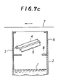
- the structures of vacuum deposition apparatuses of the prior art are schematically illustrated in Figs. 7(a), 7(b) and 7(c).
- the apparatuses comprise an evaporation chamber 2 in which a molten metal 1 is electrically heated to be vaporized in vacuo and a vapor channel 6 via which the metal vapor is directed to a substrate metal sheet (strip) 7.
- the apparatuses of Figs. 7(a) and 7(b) are adapted to a vertical vacuum deposition line and that of Fig. 7(c) is for a horizontal vacuum deposition line.
- a shutter 5 is provided at the junction of the evaporation chamber and the vapor channel. In Figs. 7(a) and 7(c) the shutter is a butterfly type and in Fig.
- the shutter 7(b) it is a slide shutter.
- the shutter is usually provided with a heater 4 for the purpose of preventing undesired solidification of metal vapor thereto.
- the butterfly valve is pivoted around a shaft 3 and the slide valve is moved horizontally by a rack-and-pinion means 3'.
- a splash-prevention board is usually provided at the junction. The deposition amount is controlled by changing the shutter aperture and electric power applied to the heater of the evaporation bath.
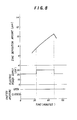
- Fig. 8 the abscissa stands for time (minutes), and shutter aperture, power supply to the evaporation heater and deposition amount (thickness, in um) are scaled on the ordinate from the bottom in this order.
- the deposition amount gradually increases, and when the electric power supply is returned to the initial level, the deposition amount gradually decreases.
- Fig. 9 the abscissa stands for time (minutes), and butterfly shutter aperture, electric power supply and deposition amount are scaled on the ordinate from the bottom in this order.
- the electric power supply is kept constant and only the butterfly valve aperture is decreased step by step from 90° to 60°, 30° and 10°, the change in deposition amount does not sensitively follow the aperture changes.
- Fig. 1 shows an embodiment of a vacuum deposition apparatus used for the method of the present invention.
- the apparatus comprises an evaporation chamber 2 and a vapor channel 6, the chamber and the channel forming substantially one chamber separated by a partition 3.
- a shutter 15 and a shutter case 4 are provided at the partition 3.
- the sliding shutter 15 (in this particular embodiment) is operated by means of a driving rod 13 which is supported by the end plate of the shutter case 4.
- the shutter 15 has an opening 19. It is desirable to design the shutter so that a small aperture remains even when the shutter is closed. When the method is applied for changing the coating amount from 0 to a certain amount, the shutter must be able to be completely closed.
- the vapor channel wall, the partition and the shutter case are provided with electric heating means to prevent undesired deposition of metal.
- the underpart of the evaporation chamber constitutes a melting bath in which the metal 1 to be deposited is melted and evaporated.
- the melting bath is provided with means for replenishment with fresh molten metal from a source placed outside of the vacuum system.
- a metal sheet or strip 7 to be coated moves past the opening of the channel 6.
- the whole apparatus is housed in a large vacuum housing as shown in Fig. 4, and the metal strip is introduced into the housing (and then into the deposition apparatus) through a seal roll system or the like known per se.
- seal roll systems are disclosed in Japanese Patent Publication No. 18646/72, Japanese Patent Publication No. 20950/78, etc.
- Figs. 3(a) (side view) and 3(b) (plan view) schematically show modifications of the above apparatus.
- a butterfly valve 25 which is pivotable about a shaft 23, a heater 24, and a pair of screens or partitions 27 are provided one on either side of the shutter.
- the aperture or aperture area cannot be clearly defined.
- Providing a butterfly valve with a pair of partitions enables the shutter aperture to be defined.
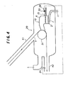
- Fig. 4 is an overall view of the vacuum deposition apparatus provided with a coating thickness detector.
- the vacuum deposition apparatus 10 is contained in a vacuum housing 20, which is evacuated through an exhaust duct 40.
- the vacuum deposition apparatus 10 is substantially the same as previously described.
- a shutter driving means 33 such as motor
- a shutter drive control means 38 and a suction pipe 11 to replenish the molten metal are shown here.
- the housing 20 is provided with an inlet path 41 and an outlet path 42 along which passes the metal strip 7 to be coated.
- the opening ends of these paths are hermetically sealed by means of a vacuum seal roll system as mentioned above to let the metal strip 7 pass into and out of the vacuum housing hermetically, although they are not shown in the drawing.
- a coating thickness detector 3 9 is provided on the outlet path 42.
- the detector can be radiation thermometer. Thickness can be detected by determining the temperature of coated film. The thicker portion is of higher temperature. Thickness also can be detected by an X-ray fluorescent analyzer. This apparatus is provided outside of the housing.
- the metal strip 7 hermetically introduced into the housing 20 passes along the inlet path 41 and around a guide roll 31, where it is coated, and moves along the outlet path 42, where a coating thickness detector 39 is mounted.
- the information collected by the detector 39 is fed back to the automatic shutter drive control means 38 to provide more precise control of the coating thickness.
- Such a feedback control system is today commercially available or easily constructed by a technician with ordinary knowledge of microcomputer technology.
- a mild steel strip 0.6 mm in thickness and 300 mm in width was vacuum deposition-coated with zinc using apparatus of Fig. 1.
- the evaporation chamber was 103 mm in length, 474 mm in width and 490 mm in height.
- the largest area of the shutter aperture was 144000 mm 2 .
- the choke condition that is, P ch /P v ⁇ 0.52 was satisfied at temperature 52 0 ° C .
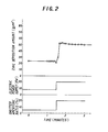
- the operation and results are illustrated in Fig. 2.
- the abscissa stands for time (minute).
- the shutter aperture (%), electric power applied to the heater of the evaporation chamber (KW) and the coating weight (g/m 2 ) are scaled from the bottom in this order.
- the coating amount control test was repeated and the relation between the coating amount change ratio, which means the flow rate change ratio (G 1/ G o ), and the shutter aperture change ratio (S i/ S o ) was checked.
- the result is shown in Fig. 5.
- the abscissa stands for the shutter aperture change ratio S 1/ S o and the ordinate represents the coating amount change ratio and the real line curve represents values calculated from the mathematical formula described above and the dots in small squares or circles represent actually measured values. From this, reliability or accuracy of the present method will be understood.
- the similar zinc vacuum deposition coating was carried out using an apparatus as illustrated in Fig. 1. This time, the coating amount was decreased.
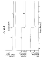
- the results are schematically illustrated in Fig. 6.
- the abscissa stands for elapsed time (minutes) and the ordinate represents zinc coating amount (um), shutter aperture (%) and electric power supply.
- the decreased coating amount stabilized in about 30 seconds. In the prior art method, this required at least 90 minutes.
Landscapes
- Chemical & Material Sciences (AREA)
- Chemical Kinetics & Catalysis (AREA)
- Engineering & Computer Science (AREA)
- Materials Engineering (AREA)
- Mechanical Engineering (AREA)
- Metallurgy (AREA)
- Organic Chemistry (AREA)
- Physical Vapour Deposition (AREA)
Applications Claiming Priority (2)
| Application Number | Priority Date | Filing Date | Title |
|---|---|---|---|
| JP59106396A JPS60251273A (ja) | 1984-05-28 | 1984-05-28 | 真空蒸発装置の蒸発量制御方法 |
| JP106396/84 | 1984-05-28 |
Publications (3)
| Publication Number | Publication Date |
|---|---|
| EP0166960A2 true EP0166960A2 (fr) | 1986-01-08 |
| EP0166960A3 EP0166960A3 (en) | 1988-03-30 |
| EP0166960B1 EP0166960B1 (fr) | 1991-08-21 |
Family
ID=14432526
Family Applications (1)
| Application Number | Title | Priority Date | Filing Date |
|---|---|---|---|
| EP85106511A Expired - Lifetime EP0166960B1 (fr) | 1984-05-28 | 1985-05-24 | Procédé de changement rapide de la quantité déposée lors du dépôt continu sous vide |
Country Status (7)
| Country | Link |
|---|---|
| US (1) | US4587134A (fr) |
| EP (1) | EP0166960B1 (fr) |
| JP (1) | JPS60251273A (fr) |
| KR (1) | KR890004044B1 (fr) |
| AU (1) | AU574469B2 (fr) |
| CA (1) | CA1249491A (fr) |
| DE (1) | DE3583829D1 (fr) |
Cited By (1)
| Publication number | Priority date | Publication date | Assignee | Title |
|---|---|---|---|---|
| US4898746A (en) * | 1988-06-28 | 1990-02-06 | Rca Licensing Corporation | Material deposition process analysis system |
Families Citing this family (16)
| Publication number | Priority date | Publication date | Assignee | Title |
|---|---|---|---|---|
| JPS62267471A (ja) * | 1986-05-16 | 1987-11-20 | Mitsubishi Heavy Ind Ltd | 真空蒸発装置の蒸発量制御方法 |
| JPS62267465A (ja) * | 1986-05-16 | 1987-11-20 | Mitsubishi Heavy Ind Ltd | 連続真空蒸着装置の蒸着室内における溶融金属表面の汚れ検出方法 |
| JPS648265A (en) * | 1987-06-30 | 1989-01-12 | Mitsubishi Heavy Ind Ltd | Method for controlling evaporation rate of vacuum deposition device |
| JPS6465257A (en) * | 1987-09-07 | 1989-03-10 | Mitsubishi Heavy Ind Ltd | Method for controlling amount of evaporation in vacuum deposition device |
| DE4442733C2 (de) * | 1994-12-01 | 2001-04-26 | Ardenne Anlagentech Gmbh | Einrichtung zur Bedampfung bandförmiger Substrate im Vakuum |
| TW340876B (en) * | 1996-03-27 | 1998-09-21 | Nisshin Steel Co Ltd | Method and apparatus for controlling the deposition amount of a plating metal as well as method and apparatus for measuring the amount of a metal vapor |
| US5951769A (en) | 1997-06-04 | 1999-09-14 | Crown Roll Leaf, Inc. | Method and apparatus for making high refractive index (HRI) film |
| US6254934B1 (en) * | 1998-07-29 | 2001-07-03 | Litton Systems, Inc. | Method for controlled deposition of mirror layers |
| EP1174526A1 (fr) * | 2000-07-17 | 2002-01-23 | Nederlandse Organisatie voor Toegepast Natuurwetenschappelijk Onderzoek TNO | Dépôt sous vide en continu |
| EP1972699A1 (fr) * | 2007-03-20 | 2008-09-24 | ArcelorMittal France | Procede de revetement d'un substrat et installation de depot sous vide d'alliage metallique |
| CN101925688B (zh) * | 2007-12-21 | 2012-12-05 | 工业等离子体服务与技术Ipst有限公司 | 用于控制真空蒸发中蒸汽流的方法和装置 |
| EP2199425A1 (fr) | 2008-12-18 | 2010-06-23 | ArcelorMittal France | Générateur de vapeur industriel pour le dépôt d'un revêtement d'alliage sur une bande métallique (II) |
| US20120052189A1 (en) * | 2010-08-30 | 2012-03-01 | Litian Liu | Vapor deposition system |
| KR102007697B1 (ko) * | 2013-02-28 | 2019-08-06 | 삼성에스디아이 주식회사 | 이차전지용 전극 제조 장치 |
| TWI582251B (zh) * | 2014-10-31 | 2017-05-11 | 財團法人工業技術研究院 | 蒸鍍系統以及蒸鍍方法 |
| CN104988462B (zh) * | 2015-07-23 | 2017-05-31 | 京东方科技集团股份有限公司 | 一种坩埚装置 |
Family Cites Families (16)
| Publication number | Priority date | Publication date | Assignee | Title |
|---|---|---|---|---|
| US2440135A (en) * | 1944-08-04 | 1948-04-20 | Alexander Paul | Method of and apparatus for depositing substances by thermal evaporation in vacuum chambers |
| GB1010456A (en) * | 1962-10-02 | 1965-11-17 | G V Planer Ltd | Means for measuring and/or controlling the evaporation rate in vacuum evaporation processes |
| US3281265A (en) * | 1963-09-17 | 1966-10-25 | United States Steel Corp | Method and apparatus for controlling coating thickness by electron beam evaporation |
| US3602190A (en) * | 1968-10-30 | 1971-08-31 | Western Electric Co | Multiple vaporizing system |
| US3690933A (en) * | 1970-05-21 | 1972-09-12 | Republic Steel Corp | Apparatus and method for continuously condensing metal vapor upon a substrate |
| BE789818A (fr) * | 1971-10-07 | 1973-04-06 | Du Pont | Composes de polycetal |
| BE790940A (fr) * | 1971-11-04 | 1973-03-01 | Rca Corp | Procede de reglage de la composition d'un film |
| GB1483966A (en) * | 1974-10-23 | 1977-08-24 | Sharp Kk | Vapourized-metal cluster ion source and ionized-cluster beam deposition |
| US4061800A (en) * | 1975-02-06 | 1977-12-06 | Applied Materials, Inc. | Vapor desposition method |
| US3971334A (en) * | 1975-03-04 | 1976-07-27 | Xerox Corporation | Coating device |
| JPS5210869A (en) * | 1975-07-15 | 1977-01-27 | Toshinori Takagi | Thin film forming method |
| DE2548357C2 (de) * | 1975-10-29 | 1983-05-26 | Robert Bosch Gmbh, 7000 Stuttgart | Einrichtung zur kontinuierlichen Vakuumbedampfung eines bandförmigen Trägermaterials mit Zink |
| US4425871A (en) * | 1981-02-09 | 1984-01-17 | Applied Magnetics Corporation | Apparatus for sensing deposition of a thin film layer of a material |
| CA1163231A (fr) * | 1981-07-24 | 1984-03-06 | Don E. Brodie | Methode de plaquage par reaction, et produit connexe |
| US4495889A (en) * | 1982-11-24 | 1985-01-29 | Riley Thomas J | Polymeric film coating apparatus |
| US4526802A (en) * | 1983-03-31 | 1985-07-02 | Clarion Co., Ltd. | Film deposition equipment |
-
1984
- 1984-05-28 JP JP59106396A patent/JPS60251273A/ja active Granted
-
1985
- 1985-05-16 CA CA000481704A patent/CA1249491A/fr not_active Expired
- 1985-05-17 US US06/735,442 patent/US4587134A/en not_active Expired - Fee Related
- 1985-05-24 EP EP85106511A patent/EP0166960B1/fr not_active Expired - Lifetime
- 1985-05-24 DE DE8585106511T patent/DE3583829D1/de not_active Expired - Lifetime
- 1985-05-28 KR KR1019850003652A patent/KR890004044B1/ko not_active Expired
- 1985-05-28 AU AU43056/85A patent/AU574469B2/en not_active Ceased
Cited By (1)
| Publication number | Priority date | Publication date | Assignee | Title |
|---|---|---|---|---|
| US4898746A (en) * | 1988-06-28 | 1990-02-06 | Rca Licensing Corporation | Material deposition process analysis system |
Also Published As
| Publication number | Publication date |
|---|---|
| US4587134A (en) | 1986-05-06 |
| EP0166960A3 (en) | 1988-03-30 |
| CA1249491A (fr) | 1989-01-31 |
| AU574469B2 (en) | 1988-07-07 |
| EP0166960B1 (fr) | 1991-08-21 |
| KR890004044B1 (ko) | 1989-10-18 |
| JPH037751B2 (fr) | 1991-02-04 |
| KR850008503A (ko) | 1985-12-18 |
| DE3583829D1 (de) | 1991-09-26 |
| AU4305685A (en) | 1985-12-05 |
| JPS60251273A (ja) | 1985-12-11 |
Similar Documents
| Publication | Publication Date | Title |
|---|---|---|
| US4587134A (en) | Method of rapidly changing deposition amount in a continuous vacuum deposition process | |
| RU2429312C1 (ru) | Промышленный парогенератор для нанесения на металлическую ленту покрытия из сплава | |
| EP1301649B1 (fr) | Depot par evaporation sous vide | |
| EP0166991B1 (fr) | Procédé et contrôle de la distribution des quantités déposées par évaporation sous vide | |
| US4895631A (en) | Process and apparatus for controlling the reactive deposit of coatings on substrates by means of magnetron cathodes | |
| CA1061656A (fr) | Dispositif d'enduction | |
| AU2001275831A1 (en) | Vapour deposition | |
| GB2057723A (en) | Method and apparatus for controlling gas flows | |
| US4655168A (en) | Continuous vacuum deposition apparatus with control panels for regulating width of vapor flow | |
| US3989862A (en) | Method and apparatus for vapor-depositing coatings on substrates | |
| JPS5789524A (en) | Method of maintaining accuracy of processing by machining equipment | |
| JPH05156419A (ja) | 合金化亜鉛めっき鋼板の合金化制御方法 | |
| WO2007045215A1 (fr) | Procede et dispositif d'evaporation de matiere destines a des revetements | |
| US3999506A (en) | Vapor deposition apparatus | |
| JPS63199868A (ja) | 真空蒸発装置内の溶融金属レベル制御装置 | |
| JPH04160159A (ja) | 帯板の皮膜形成装置 | |
| EP0798553A1 (fr) | Analyse par absorption atomique pour la mesure et le contrÔle de la quantité de vapeur métallique à déposer dans une chaîne de revêtement et appareil à cet effet | |
| JPS62270772A (ja) | 連続式真空蒸着装置の付着量のオンライン学習制御方法 | |
| DE69635591T2 (de) | Verfahren und Vorrichtung zum Regeln der Temperatur einer Reaktorwand | |
| JPS62270769A (ja) | 真空蒸発装置の蒸発量制御方法 | |
| JPS648265A (en) | Method for controlling evaporation rate of vacuum deposition device | |
| JPS6389651A (ja) | 真空蒸着装置 | |
| JPS5843451B2 (ja) | 金属ストリップ連続加熱装置の板温制御方法 | |
| JPH09316640A (ja) | 蒸着めっきの付着量制御方法及び制御装置 | |
| JPS627858A (ja) | 真空蒸着装置 |
Legal Events
| Date | Code | Title | Description |
|---|---|---|---|
| PUAI | Public reference made under article 153(3) epc to a published international application that has entered the european phase |
Free format text: ORIGINAL CODE: 0009012 |
|
| 17P | Request for examination filed |
Effective date: 19850524 |
|
| AK | Designated contracting states |
Designated state(s): BE DE FR GB |
|
| PUAL | Search report despatched |
Free format text: ORIGINAL CODE: 0009013 |
|
| AK | Designated contracting states |
Kind code of ref document: A3 Designated state(s): BE DE FR GB |
|
| 17Q | First examination report despatched |
Effective date: 19891115 |
|
| GRAA | (expected) grant |
Free format text: ORIGINAL CODE: 0009210 |
|
| AK | Designated contracting states |
Kind code of ref document: B1 Designated state(s): BE DE FR GB |
|
| REF | Corresponds to: |
Ref document number: 3583829 Country of ref document: DE Date of ref document: 19910926 |
|
| ET | Fr: translation filed | ||
| PLBE | No opposition filed within time limit |
Free format text: ORIGINAL CODE: 0009261 |
|
| STAA | Information on the status of an ep patent application or granted ep patent |
Free format text: STATUS: NO OPPOSITION FILED WITHIN TIME LIMIT |
|
| 26N | No opposition filed | ||
| PGFP | Annual fee paid to national office [announced via postgrant information from national office to epo] |
Ref country code: FR Payment date: 19960510 Year of fee payment: 12 |
|
| PGFP | Annual fee paid to national office [announced via postgrant information from national office to epo] |
Ref country code: GB Payment date: 19960515 Year of fee payment: 12 |
|
| PGFP | Annual fee paid to national office [announced via postgrant information from national office to epo] |
Ref country code: BE Payment date: 19960711 Year of fee payment: 12 |
|
| PG25 | Lapsed in a contracting state [announced via postgrant information from national office to epo] |
Ref country code: GB Effective date: 19970524 |
|
| PG25 | Lapsed in a contracting state [announced via postgrant information from national office to epo] |
Ref country code: BE Effective date: 19970531 |
|
| BERE | Be: lapsed |
Owner name: MITSUBISHI JUKOGYO K.K. Effective date: 19970531 Owner name: NISSHIN STEEL CO. LTD Effective date: 19970531 |
|
| GBPC | Gb: european patent ceased through non-payment of renewal fee |
Effective date: 19970524 |
|
| PG25 | Lapsed in a contracting state [announced via postgrant information from national office to epo] |
Ref country code: FR Free format text: LAPSE BECAUSE OF NON-PAYMENT OF DUE FEES Effective date: 19980130 |
|
| REG | Reference to a national code |
Ref country code: FR Ref legal event code: ST |
|
| PGFP | Annual fee paid to national office [announced via postgrant information from national office to epo] |
Ref country code: DE Payment date: 19990525 Year of fee payment: 15 |
|
| PG25 | Lapsed in a contracting state [announced via postgrant information from national office to epo] |
Ref country code: DE Free format text: LAPSE BECAUSE OF NON-PAYMENT OF DUE FEES Effective date: 20010301 |