EP0167289A2 - Appareil pour images transparentes - Google Patents
Appareil pour images transparentes Download PDFInfo
- Publication number
- EP0167289A2 EP0167289A2 EP85303904A EP85303904A EP0167289A2 EP 0167289 A2 EP0167289 A2 EP 0167289A2 EP 85303904 A EP85303904 A EP 85303904A EP 85303904 A EP85303904 A EP 85303904A EP 0167289 A2 EP0167289 A2 EP 0167289A2
- Authority
- EP
- European Patent Office
- Prior art keywords
- guide plate
- light guide
- light
- plate
- transparency
- Prior art date
- Legal status (The legal status is an assumption and is not a legal conclusion. Google has not performed a legal analysis and makes no representation as to the accuracy of the status listed.)
- Withdrawn
Links
Images


Classifications
-
- G—PHYSICS
- G02—OPTICS
- G02B—OPTICAL ELEMENTS, SYSTEMS OR APPARATUS
- G02B6/00—Light guides; Structural details of arrangements comprising light guides and other optical elements, e.g. couplings
- G02B6/0001—Light guides; Structural details of arrangements comprising light guides and other optical elements, e.g. couplings specially adapted for lighting devices or systems
- G02B6/0011—Light guides; Structural details of arrangements comprising light guides and other optical elements, e.g. couplings specially adapted for lighting devices or systems the light guides being planar or of plate-like form
- G02B6/0033—Means for improving the coupling-out of light from the light guide
- G02B6/0035—Means for improving the coupling-out of light from the light guide provided on the surface of the light guide or in the bulk of it
- G02B6/0045—Means for improving the coupling-out of light from the light guide provided on the surface of the light guide or in the bulk of it by shaping at least a portion of the light guide
- G02B6/0046—Tapered light guide, e.g. wedge-shaped light guide
-
- G—PHYSICS
- G02—OPTICS
- G02B—OPTICAL ELEMENTS, SYSTEMS OR APPARATUS
- G02B6/00—Light guides; Structural details of arrangements comprising light guides and other optical elements, e.g. couplings
- G02B6/0001—Light guides; Structural details of arrangements comprising light guides and other optical elements, e.g. couplings specially adapted for lighting devices or systems
- G02B6/0011—Light guides; Structural details of arrangements comprising light guides and other optical elements, e.g. couplings specially adapted for lighting devices or systems the light guides being planar or of plate-like form
- G02B6/0033—Means for improving the coupling-out of light from the light guide
- G02B6/005—Means for improving the coupling-out of light from the light guide provided by one optical element, or plurality thereof, placed on the light output side of the light guide
-
- G—PHYSICS
- G02—OPTICS
- G02B—OPTICAL ELEMENTS, SYSTEMS OR APPARATUS
- G02B6/00—Light guides; Structural details of arrangements comprising light guides and other optical elements, e.g. couplings
- G02B6/0001—Light guides; Structural details of arrangements comprising light guides and other optical elements, e.g. couplings specially adapted for lighting devices or systems
- G02B6/0011—Light guides; Structural details of arrangements comprising light guides and other optical elements, e.g. couplings specially adapted for lighting devices or systems the light guides being planar or of plate-like form
- G02B6/0066—Light guides; Structural details of arrangements comprising light guides and other optical elements, e.g. couplings specially adapted for lighting devices or systems the light guides being planar or of plate-like form characterised by the light source being coupled to the light guide
- G02B6/0068—Arrangements of plural sources, e.g. multi-colour light sources
-
- G—PHYSICS
- G02—OPTICS
- G02B—OPTICAL ELEMENTS, SYSTEMS OR APPARATUS
- G02B6/00—Light guides; Structural details of arrangements comprising light guides and other optical elements, e.g. couplings
- G02B6/0001—Light guides; Structural details of arrangements comprising light guides and other optical elements, e.g. couplings specially adapted for lighting devices or systems
- G02B6/0011—Light guides; Structural details of arrangements comprising light guides and other optical elements, e.g. couplings specially adapted for lighting devices or systems the light guides being planar or of plate-like form
- G02B6/0066—Light guides; Structural details of arrangements comprising light guides and other optical elements, e.g. couplings specially adapted for lighting devices or systems the light guides being planar or of plate-like form characterised by the light source being coupled to the light guide
- G02B6/007—Incandescent lamp or gas discharge lamp
- G02B6/0071—Incandescent lamp or gas discharge lamp with elongated shape, e.g. tube
-
- G—PHYSICS
- G02—OPTICS
- G02B—OPTICAL ELEMENTS, SYSTEMS OR APPARATUS
- G02B6/00—Light guides; Structural details of arrangements comprising light guides and other optical elements, e.g. couplings
- G02B6/0001—Light guides; Structural details of arrangements comprising light guides and other optical elements, e.g. couplings specially adapted for lighting devices or systems
- G02B6/0011—Light guides; Structural details of arrangements comprising light guides and other optical elements, e.g. couplings specially adapted for lighting devices or systems the light guides being planar or of plate-like form
- G02B6/0081—Mechanical or electrical aspects of the light guide and light source in the lighting device peculiar to the adaptation to planar light guides, e.g. concerning packaging
Definitions
- the present invention relates to a transparency apparatus for observing originals such as negative or positive films, Roentgen photos and so forth.
- an original carrying the image information to be inputted is placed on a tablet having position detecting lines arranged in X- and Y-directions, and the user traces the profile of the image by, for example, a position appointing device such as a stylus pen.
- the original carrying the image information takes the form of a negative or positive film, Roentgen photograph or the like.
- a transparency device which incorporates a translucent plate on which the original is placed, and a light source disposed under the translucent plate and adapted to illuminate the original through the translucent plate from the lower side thereof.
- the transparency device of the kind described makes use of fluorescent tubes as the light source. Since the fluorescent tubes are disposed beneath the translucent plate, the transparency device inevitably has a thickness which is greater than the diameter of the fluorescent tubes.
- the position appointing device cannot be positioned too far from the tablet of the digitizer, due to reasons concerning the characteristics of the digitizer. This in turn makes it impossible to input the image information through the transparency device placed on the tablet.
- the thickness of the transparency device be reduced by making use of tabular EL light-emitting elements in place of the translucent tubes.
- the use of expensive EL light-emitting elements undesirably raises the cost of the system as a whole.
- an object of the invention is to provide a transparency apparatus for transparency observation of an original such as a photographic film placed on a translucent observation plate, comprising: a generally rectangular tabular light guide plate having a flat upper surface, the underside of the light guide plate having at least one tapered surface which extends from a portion of the light guide plate near one longitudinal end surface of the light guide plate towards the other end such as to progressively approach the flat upper surface of the light guide plate, the portion of the upper surface opposing the tapered surface presenting an area on which the observation plate is to be seated; and a light source means from which a light is introduced into the light guide plate through the one end surface of the light guide plate.
- the greater part of the light introduced through one end surface of the light guide plate and reaching the tapered surface is totally reflected and radiated to the upper surface of the liquid guide plate.
- the light coming into the light guide plate through the incident end surface is attenuated as it travels through the light guide plate to the other end of the plate which is remote from the light source, so that the other end receives a smaller quantity of light than the incident end does.
- the totally reflected light is concentrated in the area near the other end of the light guide plate, so that light is uniformly emitted from the portion of the upper surface of the light guide plate opposing the tapered lower surface of the same. Therefore, by placing a translucent plate of, for example, white color on the above-mentioned portion of the translucent plate, it is possible to obtain an observation surface over which the light is dispersed uniformly.
- a second object of the invention is to provide a transparency apparatus of the type mentioned above, further comprising fine convexities and concavities formed on the tapered surface of the light guide plate, and a reflecting mirror disposed such as to oppose the tapered surface of the light guide plate.
- the light introduced through one end surface of the light guide plate is irregularly reflected by the fine convexities and concavities on the tapered surface of the light guide plate, and the portion of the light directed to the reflecting mirror is reflected by the mirror towards the upper surface of the light guide plate such as to be emitted uniformly and efficiently from the portion of the upper surface of the light guide plate opposite the tapered surface.
- a third object of the invention is to provide a transparency apparatus having a light source body disposed in the vicinity of one end surface of the light guide plate.
- the overall thickness of the transparency apparatus as a whole can be reduced because the light source is not disposed under the light guide plate.
- a fourth object of the invention is to provide a simple and inexpensive transparency apparatus which can be constituted by easily available parts such as an acrylic plate, reflecting mirror and so forth, without necessitating the use of a special light source such as EL light-emitting elements.
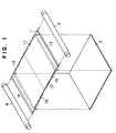
- Figs. 1 and 2 in combination show an essential portion of a light source device used in a transparency apparatus in accordance with the invention.
- the light source device has a light guide plate 1, a reflecting mirror 2, and light sources 3, 4 such as fluorescent tubes.
- the light guide plate 1 is made of a transparent material such as a colorless transparent acrylic resin, and has a flat upper surface 11.
- the underside of the light guide plate 1 has a pair of tapered surfaces 15 and 16 which start at regions near the opposite longitudinal ends of the light guide plate 1 and converge upwardly, i.e., towards the upper surface 11, substantially at the lengthwise mid point of the light guide plate 1.
- the tapered surfaces 15 and 16 are provided with fine convexities and concavities.
- the reflecting mirror 2 consists of a colorless transparent plate 2a of an acrylic resin which is lined on its under side with a reflector having a reflecting surface 2b.
- the reflecting mirror 2 is disposed such as to oppose the tapered surfaces 15 and 16 of the light guide plate 1.
- the fluorescent tubes 3 and 4 are disposed in the vicinity of respective longitudinal ends 13 and 14 of the light guide plate 1. It is to be noted that, in Fig. 2, the thickness of the light guide plate 1 is exaggerated in comparison with the length of the same, so that the light guide plate 1 shown in Fig. 2 is expanded in the thicknesswise direction as compared with the actual case, in order to clearly show the paths of light.
- the portion 17 of the upper surface 11 opposing the tapered surfaces 15 and 16 can emit the light substantially uniformly over the entire area thereof. Therefore, a transparency observation surface having a uniform light intensity distribution can be obtained by placing a translucent observation plate, e.g., the white translucent acrylic resin plate, on the portion 17 of the upper surface 11 of the light guide plate 1.
- a translucent observation plate e.g., the white translucent acrylic resin plate
- the reflecting mirror 2 has the acrylic resin plate so that the light guide plate 1 emits white light.
- the reflecting mirror 2 can have a transparent glass plate or a plate having a color other than white in place of the acrylic resin plate 2a, if it is not necessary to obtain white light. It is also possible to use a material having a specific color as the material of the light guide plate 1 and the transparency observation plate so that the light guide plate 1 or the transparency observation plate are able to emit the light of the specific color.
- the light guide plate 1 has two tapered surfaces.
- the light guide plate 1, however, can have four or more such tapered surfaces or, alternatively, the underside of the light guide plate 1 may be conically concaved such that the central portion of the light guide plate has the smallest thickness.
- Figs. 3 and 4 show the whole portion of the transparency apparatus in accordance with the invention.
- the apparatus has a main part 20, a driving unit 30, a connection cord 40 and a power supply cord 50.
- the main part 20 is constituted by a stainless steel sheet which is bent in a substantially U-shaped cross-section such as to have recesses for receiving the fluorescent tubes 3 and 4 at both longitudinal ends thereof.
- the light guide tube 1 and the reflecting mirror 2 are interposed between these recesses.
- the portion of the upper surface 21 of the main part 20 of the apparatus corresponding to the light-emitting portion 17 of the light guide plate 1 is opened and is covered by an observation plate 22 which is made of a white translucent acrylic resin.
- the main part 20 of the apparatus is protruded at its central portion such as to provide a land portion 23 of a substantial area.
- the reflecting mirror 2 is seated on this land portion 23, while the light guide plate 1 is placed on the land portion 23 through the intermediary of a spacer 24.
- Reflectors 25 and 26 each having an arcuate cross-section are disposed under the fluorescent tubes 25 and 26.
- the fluorescent lamps 3 and 4 are attached to the main part 20 through sockets which are not shown and are electrically connected to the driving unit 30 through the connection cord 40.
- the driving unit 30 is composed of a ballast, switches and other parts which are known per se, and is connected to a commercial electric power supply through the power supply cord 50.
- the apparatus as a whole is placed on a digitizer such that the tablet 60 of the digitizer is received in a tablet-receiving recess 27 formed under the land portion 23 of the main part 20, and an original such as a film is placed on the observation plate 22.
- the switch of the driving unit 30 is turned on, the original is uniformly illuminated by the light from the observation plate 22.
- the user traces the image on the original by means of the position appointing device, such as a stylus pen, so that the data is inputted to the tablet 60.
- the fluorescent tubes 3 and 4 constituting the light sources are disposed at both ends of the main part 20 and only the light guide plate 1 and the reflecting mirror 2 are laid under the observation plate 22. Therefore, the portion of the transparency apparatus which is to be placed on the tablet can have a small thickness on the order of 1 to 2 cm which is small enough to permit the inputting of the data from the upper side of the observation plate to the tablet under the apparatus without difficulty.
- the tablet 60 of the digitizer used in combination with the transparency apparatus of the invention may be of any desired type, provided that it is sensitive to the movement of the position appointing device at a height of about 1 to 2 cm above the tablet.
- the tapered surfaces 15 and 16 are slightly offset to the right from the center of the light guide plate 1, in order to align the light-emitting portion of the transparency apparatus with the data input area of the tablet 60.
- Apertures 28 which are formed in a rear portion of the main part 20 of the apparatus permit an ultrasonic timing signal to pass therethrough from a transmitter on the position appointing device to a receiver (not shown) on the tablet 60.
Landscapes
- Physics & Mathematics (AREA)
- General Physics & Mathematics (AREA)
- Optics & Photonics (AREA)
- Facsimile Scanning Arrangements (AREA)
- Investigating Materials By The Use Of Optical Means Adapted For Particular Applications (AREA)
- Investigating Or Analysing Materials By Optical Means (AREA)
- Mirrors, Picture Frames, Photograph Stands, And Related Fastening Devices (AREA)
- Illuminated Signs And Luminous Advertising (AREA)
Applications Claiming Priority (2)
| Application Number | Priority Date | Filing Date | Title |
|---|---|---|---|
| JP8484584U JPS61119U (ja) | 1984-06-07 | 1984-06-07 | 透視装置 |
| JP84845/84U | 1984-06-07 |
Publications (2)
| Publication Number | Publication Date |
|---|---|
| EP0167289A2 true EP0167289A2 (fr) | 1986-01-08 |
| EP0167289A3 EP0167289A3 (fr) | 1986-07-09 |
Family
ID=13842135
Family Applications (1)
| Application Number | Title | Priority Date | Filing Date |
|---|---|---|---|
| EP85303904A Withdrawn EP0167289A3 (fr) | 1984-06-07 | 1985-06-03 | Appareil pour images transparentes |
Country Status (2)
| Country | Link |
|---|---|
| EP (1) | EP0167289A3 (fr) |
| JP (1) | JPS61119U (fr) |
Cited By (4)
| Publication number | Priority date | Publication date | Assignee | Title |
|---|---|---|---|---|
| EP0229863A1 (fr) * | 1986-01-24 | 1987-07-29 | Franz Johnsen Vinther | Plaque éclairée |
| EP0275858A1 (fr) * | 1986-12-30 | 1988-07-27 | Abdennasser Benmouna | Caisson lumineux |
| US4794492A (en) * | 1984-08-07 | 1988-12-27 | Vinther Franz J | Illuminated board |
| EP0466119A3 (en) * | 1990-07-11 | 1997-04-16 | Gao Ges Automation Org | Apparatus and method for checking documents |
Family Cites Families (6)
| Publication number | Priority date | Publication date | Assignee | Title |
|---|---|---|---|---|
| US3457662A (en) * | 1967-05-19 | 1969-07-29 | Ben W Rau | Lighting apparatus |
| DE2150894A1 (de) * | 1971-10-13 | 1973-04-19 | Licentia Gmbh | Keilfoermiger lichtleiter aus glasklarem kunststoff oder aus glas zur gleichmaessigen beleuchtung einer langgestreckten skala |
| JPS5062595A (fr) * | 1973-10-03 | 1975-05-28 | ||
| US4285889A (en) * | 1979-12-26 | 1981-08-25 | Hughes Aircraft Company | Method for fabricating thin panel illuminator |
| DE3208162A1 (de) * | 1981-03-28 | 1982-10-07 | Teldix Gmbh | Flaechige beleuchtungseinrichtung |
| DE3123369A1 (de) * | 1981-06-12 | 1983-02-03 | Vdo Schindling | Lichtleiter |
-
1984
- 1984-06-07 JP JP8484584U patent/JPS61119U/ja active Pending
-
1985
- 1985-06-03 EP EP85303904A patent/EP0167289A3/fr not_active Withdrawn
Cited By (4)
| Publication number | Priority date | Publication date | Assignee | Title |
|---|---|---|---|---|
| US4794492A (en) * | 1984-08-07 | 1988-12-27 | Vinther Franz J | Illuminated board |
| EP0229863A1 (fr) * | 1986-01-24 | 1987-07-29 | Franz Johnsen Vinther | Plaque éclairée |
| EP0275858A1 (fr) * | 1986-12-30 | 1988-07-27 | Abdennasser Benmouna | Caisson lumineux |
| EP0466119A3 (en) * | 1990-07-11 | 1997-04-16 | Gao Ges Automation Org | Apparatus and method for checking documents |
Also Published As
| Publication number | Publication date |
|---|---|
| EP0167289A3 (fr) | 1986-07-09 |
| JPS61119U (ja) | 1986-01-06 |
Similar Documents
| Publication | Publication Date | Title |
|---|---|---|
| US3241256A (en) | Method and means for integrally lighting an indicator with uniform brightness and with light conservation | |
| TW541440B (en) | Surface light source device | |
| JPH1186620A (ja) | 照明装置および掲示板装置 | |
| US4998804A (en) | Transmissive liquid crystal display device | |
| EP1703306B1 (fr) | Système à éclairage périphérique pour un dispositif à affichage interactif et procédé pour son usage | |
| KR860001315A (ko) | 광확산기 | |
| JPH11250713A (ja) | 導光板および平面照明装置 | |
| US5852288A (en) | Bar code scanning apparatus | |
| JP2003217327A (ja) | 面光源装置 | |
| JPH11203925A (ja) | 発光パネル装置 | |
| JPH11219610A (ja) | 照明装置 | |
| EP0172615A2 (fr) | Dispositif d'affichage à cristal liquide | |
| US7575329B2 (en) | Compact illumination and magnification device | |
| US6538828B1 (en) | Magnifying page illuminator | |
| JPH09230339A (ja) | 照明装置 | |
| JP2001281008A (ja) | 照明装置 | |
| JP2005116267A (ja) | 面光源装置 | |
| JP2002109938A (ja) | 照明装置及び表示装置 | |
| JPS59147387A (ja) | 平面拡散装置 | |
| JPH0540574A (ja) | 位置認識装置 | |
| JPH11306828A (ja) | 照明装置 | |
| JPH04423Y2 (fr) | ||
| KR950033594A (ko) | 도광판 및 그것을 이용한 평면 조광장치 | |
| JPH10257247A (ja) | 画像読取り装置及びスキャナ | |
| JPH05142533A (ja) | 面発光装置 |
Legal Events
| Date | Code | Title | Description |
|---|---|---|---|
| PUAI | Public reference made under article 153(3) epc to a published international application that has entered the european phase |
Free format text: ORIGINAL CODE: 0009012 |
|
| AK | Designated contracting states |
Designated state(s): DE FR GB IT |
|
| PUAL | Search report despatched |
Free format text: ORIGINAL CODE: 0009013 |
|
| AK | Designated contracting states |
Kind code of ref document: A3 Designated state(s): DE FR GB IT |
|
| STAA | Information on the status of an ep patent application or granted ep patent |
Free format text: STATUS: THE APPLICATION IS DEEMED TO BE WITHDRAWN |
|
| 18D | Application deemed to be withdrawn |
Effective date: 19870310 |
|
| RIN1 | Information on inventor provided before grant (corrected) |
Inventor name: SAWA, HIDEO Inventor name: ETO, YOJI |