EP0167740A2 - Ultraschallwandler mit einem vielfach gefalteten piezoelektrischen polymeren Film - Google Patents
Ultraschallwandler mit einem vielfach gefalteten piezoelektrischen polymeren Film Download PDFInfo
- Publication number
- EP0167740A2 EP0167740A2 EP85105424A EP85105424A EP0167740A2 EP 0167740 A2 EP0167740 A2 EP 0167740A2 EP 85105424 A EP85105424 A EP 85105424A EP 85105424 A EP85105424 A EP 85105424A EP 0167740 A2 EP0167740 A2 EP 0167740A2
- Authority
- EP
- European Patent Office
- Prior art keywords
- polymer film
- piezoelectric polymer
- ultrasonic transducer
- folded
- piezoelectric
- Prior art date
- Legal status (The legal status is an assumption and is not a legal conclusion. Google has not performed a legal analysis and makes no representation as to the accuracy of the status listed.)
- Granted
Links
Images



Classifications
-
- G—PHYSICS
- G01—MEASURING; TESTING
- G01H—MEASUREMENT OF MECHANICAL VIBRATIONS OR ULTRASONIC, SONIC OR INFRASONIC WAVES
- G01H11/00—Measuring mechanical vibrations or ultrasonic, sonic or infrasonic waves by detecting changes in electric or magnetic properties
- G01H11/06—Measuring mechanical vibrations or ultrasonic, sonic or infrasonic waves by detecting changes in electric or magnetic properties by electric means
- G01H11/08—Measuring mechanical vibrations or ultrasonic, sonic or infrasonic waves by detecting changes in electric or magnetic properties by electric means using piezoelectric devices
-
- B—PERFORMING OPERATIONS; TRANSPORTING
- B06—GENERATING OR TRANSMITTING MECHANICAL VIBRATIONS IN GENERAL
- B06B—METHODS OR APPARATUS FOR GENERATING OR TRANSMITTING MECHANICAL VIBRATIONS OF INFRASONIC, SONIC, OR ULTRASONIC FREQUENCY, e.g. FOR PERFORMING MECHANICAL WORK IN GENERAL
- B06B1/00—Methods or apparatus for generating mechanical vibrations of infrasonic, sonic, or ultrasonic frequency
- B06B1/02—Methods or apparatus for generating mechanical vibrations of infrasonic, sonic, or ultrasonic frequency making use of electrical energy
- B06B1/06—Methods or apparatus for generating mechanical vibrations of infrasonic, sonic, or ultrasonic frequency making use of electrical energy operating with piezoelectric effect or with electrostriction
- B06B1/0688—Methods or apparatus for generating mechanical vibrations of infrasonic, sonic, or ultrasonic frequency making use of electrical energy operating with piezoelectric effect or with electrostriction with foil-type piezoelectric elements, e.g. PVDF
- B06B1/0692—Methods or apparatus for generating mechanical vibrations of infrasonic, sonic, or ultrasonic frequency making use of electrical energy operating with piezoelectric effect or with electrostriction with foil-type piezoelectric elements, e.g. PVDF with a continuous electrode on one side and a plurality of electrodes on the other side
-
- Y—GENERAL TAGGING OF NEW TECHNOLOGICAL DEVELOPMENTS; GENERAL TAGGING OF CROSS-SECTIONAL TECHNOLOGIES SPANNING OVER SEVERAL SECTIONS OF THE IPC; TECHNICAL SUBJECTS COVERED BY FORMER USPC CROSS-REFERENCE ART COLLECTIONS [XRACs] AND DIGESTS
- Y10—TECHNICAL SUBJECTS COVERED BY FORMER USPC
- Y10S—TECHNICAL SUBJECTS COVERED BY FORMER USPC CROSS-REFERENCE ART COLLECTIONS [XRACs] AND DIGESTS
- Y10S310/00—Electrical generator or motor structure
- Y10S310/80—Piezoelectric polymers, e.g. PVDF
Definitions
- This invention relates to an ultrasonic transducer with a multiple-folded piezoelectric polymer film.
- a linear array type ultrasonic transducer for use on a linear electron scanning system use may be made of an array type in which a ceramics piezoelectric substratum, such as lead titanate or lead titanate zirconate, includes strip-like elements.
- a ceramics piezoelectric substratum such as lead titanate or lead titanate zirconate
- This type of ceramics piezoelectric substratum is hard and brittle in nature and tends to produce defects and cracks when the strip-like elements are obtained. Furthermore, it is difficult to precisely form many strip-like elements. Many problems are also involved from the standpoint of manufacturing costs.
- a fluorine-containing high polymer such as polyvinylidene fluoride (PVF 2 ) or polyvinylidene-triethylene fluoride copolymer (PVF 2 ⁇ TrFE), or the other organic synthetic high polymer is polarized at high temperatures under a high electric field to manifest its piezoelectricity and pyroelectricity.
- PVF 2 polyvinylidene fluoride
- PVF 2 ⁇ TrFE polyvinylidene-triethylene fluoride copolymer
- an ultrasonic transducer has actively been developed utilizing the thickness shear mode of the piezoelectric high polymer.
- the specific acoustic impedance of this piezoelectric polymer is close to that of a human body and, moreover, a smaller elasticity is involved on the piezoelectric polymer.
- the dielectric constant of the piezoelectric polymer film is, in general, of the order of 10, i.e., prominently smaller than that of the ceramics piezoelectric substratum. Furthermore, the drive elements of the linear array type ultrasonic transducer have a smaller area and an extremely high acoustic impedance. Usually, a poor matching is involved against a 50 n power source (transmitting/receiving circuit), suffering an appreciable loss on the ultrasonic transducer.
- an ultrasonic transducer in which a plurality of piezoelectric polymer films are properly piled up to obtain a thicker polymer film while at the same time the electric impedance is lowered.
- This type of conventional ultrasonic transducer is shown in Fig. 1.
- a plurality of piezoelectric polymer films (3, 3, 3) each, have strip-like electrodes 1 on one surface and a common electrode 2 on the other surface and are piled up such that the two adjacent piezoelectric polymer films have their identical electrodes located opposite to each other as shown in Fig. 1.
- the opposite, identical electrodes of the adjacent two polymer films are connected by a solder or a conductive adhesive 4 to each other.
- the strip-like electrode 1 of the first piezoelectric polymer film is located opposite to the strip-like electrode 1 of the corresponding adjacent second piezoelectric polymer film.
- Such a type of ultrasonic transducer which lowers an electric impedance.
- Zo representing an electric impedance of, for example, a single layer of a resonant frequency f
- An electric impedance of 1/4 is involved for a two-layer structure and an electric impedance of 1/9 is involved for a three-layer structure. It is, therefore, possible to obtain an improved matching with respect to a power source.
- an ultrasonic transducer including a piezoelectric polymer film having electrodes on both the surfaces thereof and folded as at least two layers, the piezoelectric polymer film being responsive to a signal applied to the electrodes to generate an ultrasonic wave focused on one spot and being adapted to receive an ultrasonic wave to convert it to an electric signal, in which a groove is formed along a folding line-on the piezoelectric polymer film.
- reference numeral 10 shows a support made of, for example, an acrylic resin.
- a copper plate 12 is fixed on the support 10 and serves as a 200 pm-thick sound reflecting plate and a common electrode.
- a once-folded piezoelectric film 14 is disposed on the copper plate 12 and has a PVF 2 piezoelectric element 16.
- a plurality of strip-like electrodes 18 made of silver are equidistantly provided on one surface of the piezoelectric element 16 and a common electrode 20, made of silver, is provided on the whole area of the other surface of the piezoelectric element 16.
- a V-shaped groove 24 is formed on a substantially central portion of a folded area 22 of the piezoelectric element 16 such that it is located along the folding line, i.e., in a direction perpendicular to that in which the strip-like electrode 18 extends.
- the V-shaped groove 24 is formed across substantially one half of the thickness of the piezoelectric element with the common electrode 20 separated.
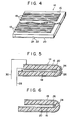
- Fig. 4 is a perspective view showing a state before the piezoelectric film 14 is folded.
- the piezoelectric body as shown in Fig. 4 is folded back upon itself along the folding line with the V-shaped groove 24 located at the outer side as shown in Fig. 3.
- the folded piezoelectric film 14 is disposed on the copper plate 12 such that the common electrode 20 is in contact with the copper plate 12.
- a conductive paste 26 which is deposited at and near the V-shaped groove 24 as shown in Fig. 3.
- the conductive paste use may be made of an epoxy resin mixed with carbon, copper or silver powders.
- the folded piezoelectric film 14 is manufactured by the following method.
- An about 1 pm-thick silver layer is deposited by, for example, a vacuum deposition method on both the surfaces of an about 50 pm-thick PVF 2 film which is obtained by a uniaxial stretching method.
- the resultant structure is polarized under an electric field of 6 KV at 100°C for 1 hour and then cooled down to room temperature to yield a PVF 2 piezoelectric element 16.
- one surface of the PVF 2 film is subjected to a patterning as shown in Fig. 4, forming a plurality of strip-like electrodes 18 in a manner to be in parallel with the direction in which uniaxial stretching is carried out.
- strip-like electrodes 64 unit electrode elements are formed having a dimension of about 0.9 mm in width x about 35 mm in length with an element-to-element gap of about 0.1 mm.
- the other surface of the PVF 2 film is subjected to a patterning to form the common electrode 20 made of silver.
- a V-shaped groove 24 of about 30 ⁇ m in depth x about 0.2 mm in width is formed by, for example, a cutter along a folding line. The resultant structure is folded back upon itself once along the V-shaped groove 24 to provide the above-mentioned PVF 2 piezoelectric film 14.
- a conductive paste 26 is deposited at and near the V-shaped groove 24 and dried to provide a folded piezoelectric film 14 in which the common electrode areas separated by the V-shaped groove are connected to each other.
- a lead 28 is connected to the copper plate 12 and a lead 30 is connected to the respective strip-like electrode 18 of the folded piezoelectric film 14 such that it is located at one end portion of the piezoelectric film 14 and on the inner side of the folded piezoelectric film 14.
- a polyester film of, for example, 12 ⁇ m in thickness is covered on the resultant structure, noting that an epoxy resin 34 is filled in a space between the polyester film 32 and the piezoelectric structure.
- the epoxy resin 34 is commercially available under the trade name of 301-2 manufactured by Epotek Co., Ltd. The presence of the epoxy resin 34 positively retains the state in which the piezoelectric film 14 is folded back upon itself, and also assures a positive fixing of the piezoelectric film 14 to the support 10.
- a folding operation can readily been carried out, since the V-shaped groove 24 is formed on one surface, for example, on the common electrode side, of the PVF 2 piezoelectric structure to be folded back upon itself.
- This specific arrangement permits the upper portion of the folded piezoelectric structure to be accurately aligned with the lower portion thereof in a substantially parallel array.
- the impedance of drive elements will vary due to a misalignment between the oppositely facing strip-like electrodes of the folded piezoelectric structure and that short-circuiting will occur between the drive elements. It is therefore possible to obtain a linear array type ultrasonic transducer of high reliability.
- the linear array type ultrasonic transducer was measured, but no electric impedance variation was not observed across the unit electrode elements.
- the ultrasonic transducer was operated at a frequency of 5 MHz.
- the PV F 2 piezoelectric transducer may be formed in a multiple-folded fashion to obtain a linear array type ultrasonic transducer of a low electric impedance. Even in this case, it is possible to readily perform such a folding operation.
- V-shaped groove 24 is formed along each folding line, preventing the folded area from being extremely bulged.
- the groove 24 is provided on one surface, for example-, on the common electrode side, of the piezoelectric film 14 such that their separated areas of the common electrode are electrically connected through the conductive paste or metal film 26 deposited at or near the groove 24.
- the metal film 26 for electrical connection may be provided, by a vapor deposition method or a sputtering method, on the V-shaped groove 24 at the folded area 22 of the piezoelectric film 14 as shown in Fig. 5.
- the piezoelectric film may be folded back upon itself with a V-shaped groove 24 internally formed along a folding line on the opposite, inner, common electrode 20 areas of the piezoelectric film.
- a conductive paste 26 may be deposited at the V-shaped groove 24 to permit the separated areas of the common electrode to be connected together.
- the leads 28 and 30 may be connected at any place to the common electrode 20 and strip-like electrode 18, respectively.
- the leads 28 and 29 may be connected to the corresponding electrodes, respectively, such that, as shown in Fig. 5, the lead 30 extends on the upper side of the electrode 20 and the lead 28 extends on the lower side of the electrode 18.
- two folded areas 22, 22 are formed on a piezoelectric element 16 to provide a three-layer piezoelectric structure as shown in Fig. 8.
- Through holes 40, 42 are formed at the folded areas of the piezoelectric element in place of the V-shaped groove 24 set out above.
- the through holes are formed, in two rows, at those locations adjacent to strip-like electrodes 18 on a piezoelectric film 14 such that they are located in a directon perpendicular to that in which the strip-like electrodes 18 extend.
- the piezoelectric film 14 is folded, along the two rows (40, 42) of the through holes, with an adhesive layer 34A initially coated thereon, providing the piezoelectric film structure with the adhesive layer filled therein.
- the piezoelectric film 14 is manufactured as follows:
- an about 1 pm-thick silver layer is deposited by, for example, a vacuum deposition method on both the surfaces of an about 50 pm-thick PVF 2 film which is obtained by a uniaxial stretching step.
- the resultant structure is polarized under an electric field of 6 KV at 100°C for one hour and cooled down to room temperature to provide a PVF 2 piezoelectric structure.
- a silver layer on one surface of the piezoelectric structure is subjected to a patterning as shown in Fig. 9 to provide strip-like electrodes 18 in a direction parallel to that in which uniaxial stretching is carried out.
- the strip-like electrodes 18 64 unit electrode elements are formed each having a dimension of 0.9 mm in width x 45 mm in length with an element-to-element gap of 0.1 mm.
- the silver layer on the other surface of the piezoelectric structure is subjected, as required, to a patterning to provide a common electrode 20.
- small through holes (40, 42) of about 50 ⁇ m in diameter are formed, by a laser beam, in two rows on those fold formation areas 22 which are adjacent to the strip-like electrodes 18.
- the resultant PVF 2 piezoelectric structure 14 is folded along two rows (40, 42) of the through holes to provide an S-shaped (three-layered) piezoelectric structure as shown in Fig.
- the adhesive is commercially available under the trade name of 301-2 manufactured by Epotek Co., Ltd.
- a lead 28 is connected to a copper plate 12 and a lead 30 is connected to the respective strip-like electrode 18.
- a polyester film 32 of, for example, 12 ⁇ m in thickness is covered on the piezoelectric structure to provide a ultrasonic transducer as shown in Fig. 8 in which the adhesive (301-2) is occupied therein.
- the piezoelectric structure is supported on a support 11.
- the piezoelectric structure is folded along the two rows (40, 42), it is possible to obtain the same effects as shown in the first embodiment of this invention. Furthermore, it is not necessary to employ any conductive paste for electrical connection, because the respective electrodes are not electrically separated by the through holes (40, 42).
- the adhesive layer 34A is passed through the through holes (40, 42) of the piezoelectric film 14 to suppress the bulging of the folded area to a small extent. At the same time, any excessive amount of adhesive in the layer-to-layer gap can be removed to form a very uniform, thin adhesive layer 34A.
- the ultrasonic transducer is operated, it is possible to eliminate a possible acoustic coupling and "electric stroke" at those areas adjacent to the strip-like electrodes where no voltage is applied.
- a force acts in a direction as indicated by arrows B, causing the adhesive to be moved toward the folded area (i.e. in a direction as indicated by an arrow A) where it is concentrated to cause the folded area to be bulged as shown in Figs. 10 and 11.
- the through holes (40, 42) are formed on the folded area of the PVF 2 piezoelectric film 14, an extra amount of adhesive is passed out through the through holes (40, 42) during the folding/cementing step to obtain an integral unit. It is also possible to obtain a modified form of PVF 2 piezoelectric film which includes, for example, a continuous, vertical, multi-folded structure including concave layers.
- the through holes, though formed by a laser beam on the PVF 2 piezoelectric film may be formed by, for example, a melting method or a mechanical method on the PVF 2 piezoelectric film.
- the through holes are formed on the non-working areas between the respective strip-like electrodes as in the second embodiment. However, they are formed on the strip-like electrodes so far as the operation of the ultrasonic transducer is not affected by the configuration of the strip-like electrodes.
- the through holes may also be formed on the boundary area between the working and non-working areas if a narrow gap is defined between the strip-like electrodes.
- the piezoelectric film may be formed with four or more folding areas, instead of being formed with two or three folding areas.
- the PVF 2 piezoelectric body use is made of a piezoelectric material, but use may also be made of a fluorine-containing synthetic high polymer, such as TrFE, or the other organic high polymers showing the piezoelectricity, or a complex piezoelectric film prepared by mixing with a high polymer resin a ceramics type piezoelectric powder such as powdered lead titanate or lead titanate zirconate.
- a fluorine-containing synthetic high polymer such as TrFE, or the other organic high polymers showing the piezoelectricity
- a complex piezoelectric film prepared by mixing with a high polymer resin a ceramics type piezoelectric powder such as powdered lead titanate or lead titanate zirconate.
Landscapes
- Engineering & Computer Science (AREA)
- Mechanical Engineering (AREA)
- Physics & Mathematics (AREA)
- General Physics & Mathematics (AREA)
- Transducers For Ultrasonic Waves (AREA)
Applications Claiming Priority (4)
| Application Number | Priority Date | Filing Date | Title |
|---|---|---|---|
| JP59122280A JPS61753A (ja) | 1984-06-14 | 1984-06-14 | 積層高分子圧電型超音波探触子 |
| JP122281/84 | 1984-06-14 | ||
| JP122280/84 | 1984-06-14 | ||
| JP59122281A JPS61754A (ja) | 1984-06-14 | 1984-06-14 | 積層高分子圧電型超音波探触子 |
Publications (3)
| Publication Number | Publication Date |
|---|---|
| EP0167740A2 true EP0167740A2 (de) | 1986-01-15 |
| EP0167740A3 EP0167740A3 (en) | 1987-07-15 |
| EP0167740B1 EP0167740B1 (de) | 1989-05-10 |
Family
ID=26459430
Family Applications (1)
| Application Number | Title | Priority Date | Filing Date |
|---|---|---|---|
| EP85105424A Expired EP0167740B1 (de) | 1984-06-14 | 1985-05-03 | Ultraschallwandler mit einem vielfach gefalteten piezoelektrischen polymeren Film |
Country Status (3)
| Country | Link |
|---|---|
| US (1) | US4725994A (de) |
| EP (1) | EP0167740B1 (de) |
| DE (1) | DE3570123D1 (de) |
Cited By (6)
| Publication number | Priority date | Publication date | Assignee | Title |
|---|---|---|---|---|
| EP0306288A3 (en) * | 1987-08-31 | 1990-06-13 | Kabushiki Kaisha Toshiba | Ultrasonic imaging apparatus |
| AU619858B2 (en) * | 1988-07-01 | 1992-02-06 | Atochem North America, Inc. | Accelerometer |
| FR2667256A1 (fr) * | 1990-10-02 | 1992-04-03 | Thomson Csf | Dispositif pour eliminer le givre forme en surface d'une paroi, notamment d'une fenetre optique ou radioelectrique. |
| WO2000079610A1 (de) * | 1999-06-19 | 2000-12-28 | Robert Bosch Gmbh | Piezoelement mit einem mittels faltung hergestellten mehrschichtaufbau |
| DE10031793C1 (de) * | 2000-07-04 | 2002-02-07 | Peter Apel | Piezoelektrischer Sensor |
| CN108906559A (zh) * | 2018-07-12 | 2018-11-30 | 四川大学 | 一种用于超声换能器的散热型电极片 |
Families Citing this family (30)
| Publication number | Priority date | Publication date | Assignee | Title |
|---|---|---|---|---|
| US4833360A (en) * | 1987-05-15 | 1989-05-23 | Board Of Regents The University Of Texas System | Sonar system using acoustically transparent continuous aperture transducers for multiple beam beamformation |
| FR2646309B1 (fr) * | 1989-04-24 | 1997-01-31 | Technomed Int Sa | Procede de fabrication d'un capteur acoustique et capteur acoustique ainsi obtenu, a couche de protection indecollable |
| NZ243294A (en) * | 1991-06-25 | 1995-04-27 | Commw Scient Ind Res Org | Time of flight of acoustic wave packets through fluid: reduction of higher order acoustic mode effects |
| DE4139024C1 (de) * | 1991-11-27 | 1993-04-15 | Siemens Ag, 8000 Muenchen, De | |
| US5315203A (en) * | 1992-04-07 | 1994-05-24 | Mcdonnell Douglas Corporation | Apparatus for passive damping of a structure |
| FI104611B (fi) * | 1993-06-21 | 2000-02-29 | Panphonics Oy | Laskostettu energiamuunnin |
| US5889354A (en) * | 1994-08-29 | 1999-03-30 | Oceaneering International Inc. | Piezoelectric unit cell |
| WO1999023486A1 (en) | 1997-10-31 | 1999-05-14 | Kawasaki Steel Corporation | Method and apparatus for ultrasonically detecting flaw on surface of circular cylinder, and method of grinding roll utilizing the same |
| JPH11299273A (ja) * | 1998-04-15 | 1999-10-29 | Minolta Co Ltd | 圧電変換素子及び圧電変換素子を使用したアクチエ−タ |
| US6138813A (en) * | 1999-06-03 | 2000-10-31 | Mars, Incorporated | Coin mechanism with a piezoelectric film sensor |
| DE19928181A1 (de) * | 1999-06-19 | 2001-01-11 | Bosch Gmbh Robert | Piezoelement mit einem Mehrschichtaufbau von Piezolagen und ein Verfahren zu dessen Herstellung |
| FI116605B (fi) * | 1999-11-05 | 2005-12-30 | Panphonics Oy | Akustinen elementti |
| JP2003520002A (ja) * | 2000-01-04 | 2003-06-24 | アメリカン・テクノロジー・コーポレーション | 圧電フィルム音波エミッタ |
| JP2001230462A (ja) | 2000-02-17 | 2001-08-24 | Minolta Co Ltd | 圧電変換素子 |
| ITPI20050095A1 (it) * | 2005-09-05 | 2005-12-05 | Federico Carpi | Attuatore, sensore e generator a polimeri elettroattivi in configurazione ripiegata |
| US8486199B2 (en) * | 2011-07-22 | 2013-07-16 | Lam Research Ag | Ultrasonic cleaning method and apparatus |
| US20130099791A1 (en) * | 2011-10-24 | 2013-04-25 | Baker Hughes Incorporated | Methodologies to Improve Reliability of Transducer Electrical Interconnections |
| US8767512B2 (en) * | 2012-05-01 | 2014-07-01 | Fujifilm Dimatix, Inc. | Multi-frequency ultra wide bandwidth transducer |
| JP2013251942A (ja) * | 2012-05-30 | 2013-12-12 | Sony Corp | 高分子アクチュエーター、アクチュエーター装置、高分子アクチュエーターの製造方法及びアクチュエーター装置の製造方法 |
| US9660170B2 (en) | 2012-10-26 | 2017-05-23 | Fujifilm Dimatix, Inc. | Micromachined ultrasonic transducer arrays with multiple harmonic modes |
| JP6464317B2 (ja) * | 2015-09-02 | 2019-02-06 | コーニンクレッカ フィリップス エヌ ヴェKoninklijke Philips N.V. | 電気活性または光活性ポリマーをベースにしたアクチュエータデバイス |
| CN105170435B (zh) * | 2015-09-23 | 2017-12-22 | 深圳先进技术研究院 | 高频超声换能器及其制备方法 |
| JP6933054B2 (ja) * | 2017-02-13 | 2021-09-08 | Tdk株式会社 | 振動デバイス |
| DE102017205375A1 (de) * | 2017-03-30 | 2018-10-04 | Robert Bosch Gmbh | Schallwandler |
| DE102017205376A1 (de) * | 2017-03-30 | 2018-10-04 | Robert Bosch Gmbh | Schallwandler |
| JP7073646B2 (ja) * | 2017-07-26 | 2022-05-24 | ヤマハ株式会社 | トランスデューサ |
| US11202049B2 (en) * | 2019-03-15 | 2021-12-14 | Comcast Cable Communications, Llc | Methods and systems for managing content items |
| CN113767646A (zh) * | 2019-05-27 | 2021-12-07 | 索尼集团公司 | 音频再现装置和音频设备 |
| EP3980739B1 (de) * | 2019-06-05 | 2026-02-04 | Liquid Wire Inc. | Verformbare sensoren mit selektiver halterung |
| JP7386324B2 (ja) * | 2020-03-31 | 2023-11-24 | 富士フイルム株式会社 | 積層圧電素子および電気音響変換器 |
Family Cites Families (13)
| Publication number | Priority date | Publication date | Assignee | Title |
|---|---|---|---|---|
| US3074327A (en) * | 1960-02-10 | 1963-01-22 | Svenska Tandsticks Aktiebolage | Method and apparatus for making fold lines in fibrous sheet material |
| US3177382A (en) * | 1961-01-25 | 1965-04-06 | Charles E Green | Mosaic construction for electroacoustical cylindrical transducers |
| NL7502453A (nl) * | 1975-03-03 | 1976-09-07 | Philips Nv | Inrichting voor het omzetten van elektrische in akoestische trillingen en omgekeerd, voorzien van een membraan, bevattende tenminste een laag piezo-elektrisch polymeer materiaal. |
| US4032929A (en) * | 1975-10-28 | 1977-06-28 | Xerox Corporation | High density linear array ink jet assembly |
| JPS52146588A (en) * | 1976-05-31 | 1977-12-06 | Matsushima Kogyo Kk | Quartz oscillator |
| US4376302A (en) * | 1978-04-13 | 1983-03-08 | The United States Of America As Represented By The Secretary Of The Navy | Piezoelectric polymer hydrophone |
| US4322877A (en) * | 1978-09-20 | 1982-04-06 | Minnesota Mining And Manufacturing Company | Method of making piezoelectric polymeric acoustic transducer |
| JPS55115799A (en) * | 1979-02-28 | 1980-09-05 | Kureha Chem Ind Co Ltd | Macromolecular piezoelectric film transducer of multiplex constitution |
| JPS55151893A (en) * | 1979-05-16 | 1980-11-26 | Toray Ind Inc | Ultrasonic transducer using high molecular piezoelectric film |
| JPS5647199A (en) * | 1979-09-26 | 1981-04-28 | Toray Ind Inc | Polymer piezoelectric transducer of multilayered lamination type |
| US4330730A (en) * | 1980-03-27 | 1982-05-18 | Eastman Kodak Company | Wound piezoelectric polymer flexure devices |
| JPS5943356A (ja) * | 1982-09-06 | 1984-03-10 | Kureha Chem Ind Co Ltd | 超音波探触子 |
| JPS6054599A (ja) * | 1983-09-05 | 1985-03-29 | Toshiba Corp | リニア・アレイ型超音波探触子 |
-
1985
- 1985-05-02 US US06/729,734 patent/US4725994A/en not_active Expired - Fee Related
- 1985-05-03 DE DE8585105424T patent/DE3570123D1/de not_active Expired
- 1985-05-03 EP EP85105424A patent/EP0167740B1/de not_active Expired
Cited By (8)
| Publication number | Priority date | Publication date | Assignee | Title |
|---|---|---|---|---|
| EP0306288A3 (en) * | 1987-08-31 | 1990-06-13 | Kabushiki Kaisha Toshiba | Ultrasonic imaging apparatus |
| AU619858B2 (en) * | 1988-07-01 | 1992-02-06 | Atochem North America, Inc. | Accelerometer |
| FR2667256A1 (fr) * | 1990-10-02 | 1992-04-03 | Thomson Csf | Dispositif pour eliminer le givre forme en surface d'une paroi, notamment d'une fenetre optique ou radioelectrique. |
| US5172024A (en) * | 1990-10-02 | 1992-12-15 | Thomson-Csf | Device for the removal of the ice formed on the surface of a wall, notably an optical or radio-electrical window |
| WO2000079610A1 (de) * | 1999-06-19 | 2000-12-28 | Robert Bosch Gmbh | Piezoelement mit einem mittels faltung hergestellten mehrschichtaufbau |
| DE10031793C1 (de) * | 2000-07-04 | 2002-02-07 | Peter Apel | Piezoelektrischer Sensor |
| CN108906559A (zh) * | 2018-07-12 | 2018-11-30 | 四川大学 | 一种用于超声换能器的散热型电极片 |
| CN108906559B (zh) * | 2018-07-12 | 2023-11-28 | 四川大学 | 一种用于超声换能器的散热型电极片 |
Also Published As
| Publication number | Publication date |
|---|---|
| US4725994A (en) | 1988-02-16 |
| DE3570123D1 (en) | 1989-06-15 |
| EP0167740B1 (de) | 1989-05-10 |
| EP0167740A3 (en) | 1987-07-15 |
Similar Documents
| Publication | Publication Date | Title |
|---|---|---|
| EP0167740B1 (de) | Ultraschallwandler mit einem vielfach gefalteten piezoelektrischen polymeren Film | |
| US5834880A (en) | Multilayer array ultrasonic transducers | |
| US6996883B2 (en) | Method of manufacturing a multi-piezoelectric layer ultrasonic transducer for medical imaging | |
| US7148608B2 (en) | Multi-layer ceramic acoustic transducer | |
| EP0379229B1 (de) | Ultraschallsonde | |
| US4424465A (en) | Piezoelectric vibration transducer | |
| US5920972A (en) | Interconnection method for a multilayer transducer array | |
| US4701659A (en) | Piezoelectric ultrasonic transducer with flexible electrodes adhered using an adhesive having anisotropic electrical conductivity | |
| US5920523A (en) | Two-dimensional acoustic array and method for the manufacture thereof | |
| EP0187668B1 (de) | Ultraschallwandler und sein Herstellungsverfahren | |
| US5153859A (en) | Laminated piezoelectric structure and process of forming the same | |
| US6014898A (en) | Ultrasonic transducer array incorporating an array of slotted transducer elements | |
| US7156938B2 (en) | Method for making multi-layer ceramic acoustic transducer | |
| US4627138A (en) | Method of making piezoelectric/pyroelectric elements | |
| US4469978A (en) | Electrode arrangement for a folded polymer piezoelectric ultrasonic detector | |
| EP0265679B1 (de) | Biegungsscheibenwandler | |
| US5757727A (en) | Two-dimensional acoustic array and method for the manufacture thereof | |
| JPH0683516B2 (ja) | 超音波探触子およびその製造方法 | |
| JPS6181000A (ja) | 積層高分子圧電型超音波探触子 | |
| JPS6054599A (ja) | リニア・アレイ型超音波探触子 | |
| JPS6269800A (ja) | 高分子圧電型超音波探触子 | |
| JPS61753A (ja) | 積層高分子圧電型超音波探触子 | |
| JPH0657080B2 (ja) | 超音波探触子およびその製造方法 | |
| JPS61754A (ja) | 積層高分子圧電型超音波探触子 | |
| JPS61294997A (ja) | 高分子圧電型超音波探触子 |
Legal Events
| Date | Code | Title | Description |
|---|---|---|---|
| PUAI | Public reference made under article 153(3) epc to a published international application that has entered the european phase |
Free format text: ORIGINAL CODE: 0009012 |
|
| 17P | Request for examination filed |
Effective date: 19850531 |
|
| AK | Designated contracting states |
Designated state(s): DE FR NL |
|
| PUAL | Search report despatched |
Free format text: ORIGINAL CODE: 0009013 |
|
| AK | Designated contracting states |
Kind code of ref document: A3 Designated state(s): DE FR NL |
|
| 17Q | First examination report despatched |
Effective date: 19880916 |
|
| GRAA | (expected) grant |
Free format text: ORIGINAL CODE: 0009210 |
|
| AK | Designated contracting states |
Kind code of ref document: B1 Designated state(s): DE FR NL |
|
| REF | Corresponds to: |
Ref document number: 3570123 Country of ref document: DE Date of ref document: 19890615 |
|
| ET | Fr: translation filed | ||
| PLBE | No opposition filed within time limit |
Free format text: ORIGINAL CODE: 0009261 |
|
| STAA | Information on the status of an ep patent application or granted ep patent |
Free format text: STATUS: NO OPPOSITION FILED WITHIN TIME LIMIT |
|
| 26N | No opposition filed | ||
| PGFP | Annual fee paid to national office [announced via postgrant information from national office to epo] |
Ref country code: FR Payment date: 19940511 Year of fee payment: 10 Ref country code: DE Payment date: 19940511 Year of fee payment: 10 |
|
| PGFP | Annual fee paid to national office [announced via postgrant information from national office to epo] |
Ref country code: NL Payment date: 19940531 Year of fee payment: 10 |
|
| PG25 | Lapsed in a contracting state [announced via postgrant information from national office to epo] |
Ref country code: NL Effective date: 19951201 |
|
| NLV4 | Nl: lapsed or anulled due to non-payment of the annual fee |
Effective date: 19951201 |
|
| PG25 | Lapsed in a contracting state [announced via postgrant information from national office to epo] |
Ref country code: DE Effective date: 19960201 |
|
| PG25 | Lapsed in a contracting state [announced via postgrant information from national office to epo] |
Ref country code: FR Effective date: 19960229 |
|
| REG | Reference to a national code |
Ref country code: FR Ref legal event code: ST |
|
| REG | Reference to a national code |
Ref country code: FR Ref legal event code: ST |