EP0167794A1 - Luftansauganlage einer Mehrzylinder-Brennkraftmaschine - Google Patents
Luftansauganlage einer Mehrzylinder-Brennkraftmaschine Download PDFInfo
- Publication number
- EP0167794A1 EP0167794A1 EP85106780A EP85106780A EP0167794A1 EP 0167794 A1 EP0167794 A1 EP 0167794A1 EP 85106780 A EP85106780 A EP 85106780A EP 85106780 A EP85106780 A EP 85106780A EP 0167794 A1 EP0167794 A1 EP 0167794A1
- Authority
- EP
- European Patent Office
- Prior art keywords
- resonance
- air intake
- intake system
- bypass
- pipe
- Prior art date
- Legal status (The legal status is an assumption and is not a legal conclusion. Google has not performed a legal analysis and makes no representation as to the accuracy of the status listed.)
- Granted
Links
Images
Classifications
-
- F—MECHANICAL ENGINEERING; LIGHTING; HEATING; WEAPONS; BLASTING
- F02—COMBUSTION ENGINES; HOT-GAS OR COMBUSTION-PRODUCT ENGINE PLANTS
- F02B—INTERNAL-COMBUSTION PISTON ENGINES; COMBUSTION ENGINES IN GENERAL
- F02B27/00—Use of kinetic or wave energy of charge in induction systems, or of combustion residues in exhaust systems, for improving quantity of charge or for increasing removal of combustion residues
- F02B27/02—Use of kinetic or wave energy of charge in induction systems, or of combustion residues in exhaust systems, for improving quantity of charge or for increasing removal of combustion residues the systems having variable, i.e. adjustable, cross-sectional areas, chambers of variable volume, or like variable means
- F02B27/0226—Use of kinetic or wave energy of charge in induction systems, or of combustion residues in exhaust systems, for improving quantity of charge or for increasing removal of combustion residues the systems having variable, i.e. adjustable, cross-sectional areas, chambers of variable volume, or like variable means characterised by the means generating the charging effect
- F02B27/0247—Plenum chambers; Resonance chambers or resonance pipes
- F02B27/0252—Multiple plenum chambers or plenum chambers having inner separation walls, e.g. comprising valves for the same group of cylinders
-
- F—MECHANICAL ENGINEERING; LIGHTING; HEATING; WEAPONS; BLASTING
- F02—COMBUSTION ENGINES; HOT-GAS OR COMBUSTION-PRODUCT ENGINE PLANTS
- F02B—INTERNAL-COMBUSTION PISTON ENGINES; COMBUSTION ENGINES IN GENERAL
- F02B27/00—Use of kinetic or wave energy of charge in induction systems, or of combustion residues in exhaust systems, for improving quantity of charge or for increasing removal of combustion residues
- F02B27/02—Use of kinetic or wave energy of charge in induction systems, or of combustion residues in exhaust systems, for improving quantity of charge or for increasing removal of combustion residues the systems having variable, i.e. adjustable, cross-sectional areas, chambers of variable volume, or like variable means
-
- F—MECHANICAL ENGINEERING; LIGHTING; HEATING; WEAPONS; BLASTING
- F02—COMBUSTION ENGINES; HOT-GAS OR COMBUSTION-PRODUCT ENGINE PLANTS
- F02B—INTERNAL-COMBUSTION PISTON ENGINES; COMBUSTION ENGINES IN GENERAL
- F02B27/00—Use of kinetic or wave energy of charge in induction systems, or of combustion residues in exhaust systems, for improving quantity of charge or for increasing removal of combustion residues
- F02B27/02—Use of kinetic or wave energy of charge in induction systems, or of combustion residues in exhaust systems, for improving quantity of charge or for increasing removal of combustion residues the systems having variable, i.e. adjustable, cross-sectional areas, chambers of variable volume, or like variable means
- F02B27/0205—Use of kinetic or wave energy of charge in induction systems, or of combustion residues in exhaust systems, for improving quantity of charge or for increasing removal of combustion residues the systems having variable, i.e. adjustable, cross-sectional areas, chambers of variable volume, or like variable means characterised by the charging effect
- F02B27/021—Resonance charging
-
- F—MECHANICAL ENGINEERING; LIGHTING; HEATING; WEAPONS; BLASTING
- F02—COMBUSTION ENGINES; HOT-GAS OR COMBUSTION-PRODUCT ENGINE PLANTS
- F02B—INTERNAL-COMBUSTION PISTON ENGINES; COMBUSTION ENGINES IN GENERAL
- F02B27/00—Use of kinetic or wave energy of charge in induction systems, or of combustion residues in exhaust systems, for improving quantity of charge or for increasing removal of combustion residues
- F02B27/02—Use of kinetic or wave energy of charge in induction systems, or of combustion residues in exhaust systems, for improving quantity of charge or for increasing removal of combustion residues the systems having variable, i.e. adjustable, cross-sectional areas, chambers of variable volume, or like variable means
- F02B27/0226—Use of kinetic or wave energy of charge in induction systems, or of combustion residues in exhaust systems, for improving quantity of charge or for increasing removal of combustion residues the systems having variable, i.e. adjustable, cross-sectional areas, chambers of variable volume, or like variable means characterised by the means generating the charging effect
- F02B27/0242—Fluid communication passages between intake ducts, runners or chambers
-
- F—MECHANICAL ENGINEERING; LIGHTING; HEATING; WEAPONS; BLASTING
- F02—COMBUSTION ENGINES; HOT-GAS OR COMBUSTION-PRODUCT ENGINE PLANTS
- F02B—INTERNAL-COMBUSTION PISTON ENGINES; COMBUSTION ENGINES IN GENERAL
- F02B75/00—Other engines
- F02B75/16—Engines characterised by number of cylinders, e.g. single-cylinder engines
- F02B75/18—Multi-cylinder engines
- F02B2075/1804—Number of cylinders
- F02B2075/1824—Number of cylinders six
-
- F—MECHANICAL ENGINEERING; LIGHTING; HEATING; WEAPONS; BLASTING
- F02—COMBUSTION ENGINES; HOT-GAS OR COMBUSTION-PRODUCT ENGINE PLANTS
- F02B—INTERNAL-COMBUSTION PISTON ENGINES; COMBUSTION ENGINES IN GENERAL
- F02B27/00—Use of kinetic or wave energy of charge in induction systems, or of combustion residues in exhaust systems, for improving quantity of charge or for increasing removal of combustion residues
- F02B27/02—Use of kinetic or wave energy of charge in induction systems, or of combustion residues in exhaust systems, for improving quantity of charge or for increasing removal of combustion residues the systems having variable, i.e. adjustable, cross-sectional areas, chambers of variable volume, or like variable means
- F02B27/0226—Use of kinetic or wave energy of charge in induction systems, or of combustion residues in exhaust systems, for improving quantity of charge or for increasing removal of combustion residues the systems having variable, i.e. adjustable, cross-sectional areas, chambers of variable volume, or like variable means characterised by the means generating the charging effect
- F02B27/0268—Valves
- F02B27/0273—Flap valves
-
- F—MECHANICAL ENGINEERING; LIGHTING; HEATING; WEAPONS; BLASTING
- F02—COMBUSTION ENGINES; HOT-GAS OR COMBUSTION-PRODUCT ENGINE PLANTS
- F02B—INTERNAL-COMBUSTION PISTON ENGINES; COMBUSTION ENGINES IN GENERAL
- F02B75/00—Other engines
- F02B75/16—Engines characterised by number of cylinders, e.g. single-cylinder engines
- F02B75/18—Multi-cylinder engines
- F02B75/22—Multi-cylinder engines with cylinders in V, fan, or star arrangement
-
- Y—GENERAL TAGGING OF NEW TECHNOLOGICAL DEVELOPMENTS; GENERAL TAGGING OF CROSS-SECTIONAL TECHNOLOGIES SPANNING OVER SEVERAL SECTIONS OF THE IPC; TECHNICAL SUBJECTS COVERED BY FORMER USPC CROSS-REFERENCE ART COLLECTIONS [XRACs] AND DIGESTS
- Y02—TECHNOLOGIES OR APPLICATIONS FOR MITIGATION OR ADAPTATION AGAINST CLIMATE CHANGE
- Y02T—CLIMATE CHANGE MITIGATION TECHNOLOGIES RELATED TO TRANSPORTATION
- Y02T10/00—Road transport of goods or passengers
- Y02T10/10—Internal combustion engine [ICE] based vehicles
- Y02T10/12—Improving ICE efficiencies
Definitions
- the invention relates to an air intake system of a multi-cylinder internal combustion engine according to the preamble of claim 1.
- Such a gas dynamic vibration system described in P 34 08 899.7 has a certain natural vibration number, which is determined by the volumes of the resonance containers and by the cross section and the length of the connecting pipe. If this natural vibration number approximately matches the frequency of the discontinuous, unsteady suction flow of the cylinders, resonance occurs.
- the gas vibrations excited by the suction effect of the cylinders are amplified and cause a charging effect of the cylinders, which leads to a better filling level and thus to an increase in torque and performance.
- the disadvantage here is that such an air intake system must be adapted to the cylinder displacement and the desired torque curve of the internal combustion engine, which results in a variety of sizes.
- the characteristic features of claim 1 serve to solve this problem. If the flow cross-section is increased from one resonance vessel to the other, the natural vibration number increases; the resonance point and the excessive torque can be moved to a higher speed range. This enlargement is difficult to achieve continuously accomplish this, since the cross-section of the connection must be constant over the entire length from the one to the other resonance container, in order not to adversely affect the shape of the vibration with the middle vibration node.
- One or more bypass tubes are therefore laid parallel to the connecting tube, the air passage surfaces of which can be controlled by throttle valves or valve bodies.
- the throttle valves are arranged so that when they open or close, in addition to changing the resonance-effective connection cross-section, the total volume of the air intake system is also changed.
- This measure also makes it possible to reduce the so-called idle sawing in injection engine, which is caused by periodic fluctuations in the speed of the engine.
- the reason for this is that the amount of air actually sucked in by the engine at the intake valve is not identical in the unsteady state with the amount of air measured by the air flow meter of the injection system. Because of dynamic effects, the pressure change in the intake manifold corresponding to the amount of air sucked in is only converted with a phase shift into a change in the volume flow on the air flow meter. The air flow meter can therefore not provide a correctly assigned signal for the formation of the desired mixture composition.
- the volume of the air intake system is therefore reduced to a minimum by switching off the connecting pipe and a bypass pipe when idling and in the lower speed range.
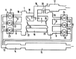
- An I-shaped distributor piece 4 is formed from a resonance container 1, a resonance container 2 and a connecting pipe 3;
- a suction nozzle 5, which contains a throttle valve 6, is connected perpendicularly to the connecting pipe 3.
- From the resonance tanks 1 and 2 each go out three suction pipes 8, which are parallel to the connecting pipe 3 and narrow conically from the resonance tanks to the inlet channels of the two cylinder groups 9, 10 each consisting of three cylinders.
- One cylinder group 9 comprises cylinders Z1, Z2, Z3, the other cylinder group 10 includes cylinders Z4, Z5, Z6.
- the exhaust gases of the two cylinder groups 9, 10 are fed via exhaust manifolds 11, 12 to an exhaust pipe 13 and, after flowing through a pre-silencer 14 and a main silencer 15, are released into the open.
- the suction nozzle 5 is connected via a suction line 16 to an air filter 17 through which the air is sucked in from the atmosphere.
- a bypass pipe 18 and a bypass pipe 19 are laid parallel to the connecting pipe 3 between the resonance containers 1 and 2.
- One bypass tube 18 is connected to the air filter 17 through a suction nozzle 20, which contains a throttle valve 21.
- throttle valves 22 and 23 or 24 and 25 are arranged at the junction points with the resonance containers 1 and 2.
- the air supply is regulated via the throttle valves of the intake manifold, which are operated with register control.
- the throttle valves 22, 23 and 24 and 25 are closed. Air is therefore only sucked in via the bypass pipe 18, the cylinders Z1, Z6, Z2, Z4, Z5, Z3 being successively corresponding to their firing order via the intake pipe assigned to them Draw in air from the resonance tanks. This results in an approximately diagonal flow through the distributor piece, which continues in the respective suction pipes. From a speed of approx. 3500 / min. the connecting pipe 3 is switched on by opening the throttle valve 6 in the suction port 5 and the throttle valves 24, 25. The throttle valves 22, 23 of the second bypass tube 19 are only at full load, from a speed of about 5700 / min. open.
Landscapes
- Engineering & Computer Science (AREA)
- Chemical & Material Sciences (AREA)
- Combustion & Propulsion (AREA)
- Mechanical Engineering (AREA)
- General Engineering & Computer Science (AREA)
- Characterised By The Charging Evacuation (AREA)
Abstract
Description
- Die Erfindung betrifft eine Luftansauganlage einer Mehrzylinder-Brennkraftmaschine nach dem Oberbegriff des Anspruchs 1.
- Ein solches, in P 34 08 899.7 beschriebenes gasdymamisches Schwingsystem weist eine bestimmte Eigenschwingungszahl auf, die durch die Volumina der Resonanzbehälter sowie durch den Querschnitt und die Länge des Verbindungsrohres festgelegt ist. Wenn diese Eigenschwingungszahl mit der Frequenz der diskontinuierlichen, instationären Saugströmung der Zylinder annähernd übereinstimmt, tritt Resonanz auf. Die von der, Saugwirkung der Zylinder erregten Gasschwingungen werden verstärkt und bewirken einen Aufladeeffekt der Zylinder., der zu einem besseren Füllungsgrad und damit zu einer Steigerung des Drehmoments und der Leistung führt. Nachteilig ist hierbei, daß eine solche Luftansauganlage jeweils an das Zylinder-Hubvolumen und den gewünschten Drehmomentverlauf der Brennkraftmaschine angepaßt werden muß, wodurch sich eine Vielzahl von Größenausführungen ergibt.
- Es ist die Aufgabe der Erfindung, durch eine besondere Gestaltung einer derartigen Luftansauganlage sie für unterschiedliche Brennkraftmaschinen brauchbar zu machen und einen optimalen Drehmomentverlauf über der Drehzahl zu erzielen.
- Zur Lösung dieser Aufgabe dienen die kennzeichnenden Merkmale des Anspruchs 1. Wird der Durchflußquerschnitt von einem zum anderen Resonanzbehälter vergrößert, so steigt die Eigenschwingungszahl an; die Resonanzstelle und die Drehmomentüberhöhung kann in einen höheren Drehzahlbereich verlegt werden. Kontinuierlich läßt sich diese Vergrößerung nur sehr schwer bewerkstelligen, da der Verbindungsquerschnitt über die ganze Länge von dem einen zum anderen Resonanzbehälter konstant sein muß, um die Schwingungsform mit mittlerem Schwingungsknoten nicht nachteilig zu beeinflussen. Es werden deshalb nach Anspruch 2 ein oder mehrere Bypassrohre parallel zum Verbindungsrohr verlegt, deren Luftdurchtrittsflächen durch Drosselklappen oder Ventilkörper steuerbar sind.
- Die Drosselklappen sind hierbei so angeordnet, daß bei deren öffnen oder Schließen neben der Veränderung des resonanzwirksamen Verbindungsquerschnittes auch das Gesamtvolumen der Luftsansauganlage verändert wird. Diese Maßnahme gestattet es auch, das sogenannte Leerlaufsägen bei Einspritzbrennkraftmaschinen zu vermindern, das durch periodische Drehzahlschwankungen der Brennkraftmaschine zustandekommt. Die Ursache hierfür ist, daß die tatsächlich vom Motor am Einlaßventil angesaugte Luftmenge im instationären Zustand nicht identisch ist mit der vom Luftmengenmesser der Einspritzanlage gemessenen Luftmenge. Denn infolge dynamischer Effekte wird die der angesaugten Luftmenge entsprechende Druckänderung im Saugrohr nur mit einer Phasenverschiebung in eine Änderung des Volumenstroms am Luftmengenmesser umgesetzt. Der Luftmengenmesser kann daher kein zeitlich richtig zugeordnetes Signal zur Bildung der gewünschten Gemischzusammensetzung liefern. Das ganze Ansaug- und Einspritzsystem wird instabil und schaukelt sich bei Leerlauf der Brennkraftmaschine zu erheblichen Drehzahlschwankungen auf, deren Amplitude um so größer ist, je größer das Verhältnis des Gesamtvolumens der Luftansauganlage zum Hubvolumen der Zylinder ist. Gemäß einer weiteren Ausgestaltung der Erfindung wird daher bei Leerlauf und im unteren Drehzahlbereich das Volumen der Luftansauganlage durch Abschalten des Verbindungsrohres und eines Bypassrohres auf ein Mindestmaß reduziert.
- Ein Ausführungsbeispiel der Erfindung ist in der Zeichnung dargestellt und wird nachfolgend erläutert.
- Aus einem Resonanzbehälter 1, einem Resonanzbehälter 2 und einem Verbindungsrohr 3 ist ein I-förmiges Verteilerstück 4 gebildet; senkrecht an das Verbindungsrohr 3 ist ein Saugstutzen 5 angeschlossen, der eine Drosselklappe 6 enthält. Von den Resonanzbehältern 1 und 2 gehen je drei Saugrohre 8 aus, die parallel zum Verbindungsrohr 3 liegen und sich von den Resonanzbehältern zu den Einlaßkanälen der beiden, aus je drei Zylindern bestehenden Zylindergruppen 9, 10 hin konisch verengen. Die eine Zylindergruppe 9 umfaßt die Zylinder Z1, Z2, Z3, die andere Zylindergruppe 10 die Zylinder Z4, Z5, Z6.
- Die Abgase der beiden Zylindergruppen 9, 10 sind über Abgassammelrohre 11, 12 einer Abgasleitung 13 zugeführt und gelangen nach Durchströmen eines Vorschalldämpfers 14 und eines Hauptschalldämpfers 15 ins Freie. Der Saugstutzen 5 ist über eine Saugleitung 16 mit einem Luftfilter 17 verbunden, durch das hindurch die Luft aus der Atmosphäre angesaugt wird.
- Parallel zum Verbindungsrohr 3 ist zwischen den Resonanzbehältern 1 und 2 ein Bypassrohr 18 und ein Bypassrohr 19 verlegt. Das eine Bypassrohr 18 ist durch einen Saugstutzen 20, der eine Drosselklappe 21 enthält, an das Luftfilter 17 angeschlossen. Am anderen Bypassrohr 19 und am Verbindungsrohr 3 sind Drosselklappen 22 und 23 bzw. 24 und 25 an den Einmündungsstellen zu den Resonanzbehältern 1 und 2 angeordnet. Die Luftzufuhr wird über die Drosselklappen der Saugstutzen, die mit Registersteuerung betätigt werden, geregelt.
- Bei Leerlauf und im unteren Drehzahlbereich der Brennkraftmaschine, bis zu einer Drehzahl von ca. 3500/min. sind die Drosselklappen 22, 23 sowie 24 und 25 geschlossen. Es wird deshalb lediglich über das Bypassrohr 18 Luft angesaugt, wobei nacheinander die Zylinder Z1, Z6, Z2, Z4, Z5, Z3 entsprechend ihrer Zündfolge über das ihnen zugeordnete Saugrohr Luft aus den Resonanzbehältern ansaugen. Hierbei ergibt sich eine annähernd diagonale Durchströmung des Verteilerstücks, die sich in den jeweiligen Saugrohren fortsetzt. Ab einer Drehzahl von ca. 3500/min. wird durch öffnen der Drosselklappe 6 im Saugstutzen 5 und der Drosselklappen 24, 25 das Verbindungsrohr 3 zugeschaltet. Die Drosselklappen 22, 23 des zweiten Bypassrohres 19 werden erst bei Vollast, ab einer Drehzahl von ca. 5700/min. geöffnet.
Claims (7)
Applications Claiming Priority (2)
| Application Number | Priority Date | Filing Date | Title |
|---|---|---|---|
| DE3424433 | 1984-07-03 | ||
| DE19843424433 DE3424433A1 (de) | 1984-07-03 | 1984-07-03 | Luftansauganlage einer mehrzylinder-brennkraftmaschine |
Publications (2)
| Publication Number | Publication Date |
|---|---|
| EP0167794A1 true EP0167794A1 (de) | 1986-01-15 |
| EP0167794B1 EP0167794B1 (de) | 1988-08-17 |
Family
ID=6239718
Family Applications (1)
| Application Number | Title | Priority Date | Filing Date |
|---|---|---|---|
| EP85106780A Expired EP0167794B1 (de) | 1984-07-03 | 1985-06-01 | Luftansauganlage einer Mehrzylinder-Brennkraftmaschine |
Country Status (4)
| Country | Link |
|---|---|
| US (1) | US4622926A (de) |
| EP (1) | EP0167794B1 (de) |
| JP (1) | JPH0830417B2 (de) |
| DE (2) | DE3424433A1 (de) |
Cited By (7)
| Publication number | Priority date | Publication date | Assignee | Title |
|---|---|---|---|---|
| EP0278071A1 (de) * | 1987-01-31 | 1988-08-17 | Dr.Ing.h.c. F. Porsche Aktiengesellschaft | Saugrorhanlage für einen Hubkolbenmotor |
| EP0628707A1 (de) * | 1993-05-07 | 1994-12-14 | Dr.Ing.h.c. F. Porsche Aktiengesellschaft | Luftansaugsystem einer Brennkraftmaschine |
| EP0688943A1 (de) * | 1994-05-19 | 1995-12-27 | Dr.Ing.h.c. F. Porsche Aktiengesellschaft | Luftansaugeanlage einer mehrzylindrigen Brennkraftmaschine |
| WO1998015727A1 (de) * | 1996-10-10 | 1998-04-16 | Filterwerk Mann+Hummel Gmbh | Ansaugsystem für eine brennkraftmaschine |
| DE202005012434U1 (de) * | 2005-08-04 | 2006-12-07 | Mann + Hummel Gmbh | Saugrohranlage mit einem Resonanzbehälter |
| DE10217760B4 (de) * | 2002-04-20 | 2010-08-12 | Mahle Filtersysteme Gmbh | Frischgasversorgungsanlage für eine Brennkraftmaschine |
| CN112796872A (zh) * | 2020-12-21 | 2021-05-14 | 中国船舶重工集团公司第七一一研究所 | 一种谐振进气的柴油机系统 |
Families Citing this family (31)
| Publication number | Priority date | Publication date | Assignee | Title |
|---|---|---|---|---|
| JPS57162634U (de) * | 1981-04-06 | 1982-10-13 | ||
| JPH0439405Y2 (de) * | 1985-03-28 | 1992-09-16 | ||
| JPH0723696B2 (ja) * | 1985-03-30 | 1995-03-15 | ヤマハ発動機株式会社 | エンジンの吸気装置 |
| JPH075249Y2 (ja) * | 1985-04-11 | 1995-02-08 | 日産自動車株式会社 | 内燃機関の吸気路装置 |
| DE3544122A1 (de) * | 1985-12-13 | 1987-06-19 | Bayerische Motoren Werke Ag | Mehrzylinder-brennkraftmaschine mit ansauganlage |
| JPH07101008B2 (ja) * | 1986-01-14 | 1995-11-01 | ヤマハ発動機株式会社 | 多気筒エンジンの吸気装置 |
| JPS62132222U (de) * | 1986-02-14 | 1987-08-20 | ||
| JPH0758049B2 (ja) * | 1986-03-08 | 1995-06-21 | ヤマハ発動機株式会社 | V型多気筒内燃機関の吸気装置 |
| JPH0742861B2 (ja) * | 1986-03-10 | 1995-05-15 | ヤマハ発動機株式会社 | 内燃機関の吸気装置 |
| JPS62214222A (ja) * | 1986-03-14 | 1987-09-21 | Yamaha Motor Co Ltd | エンジンの吸気装置 |
| JPH0717784Y2 (ja) * | 1986-06-02 | 1995-04-26 | 日産自動車株式会社 | 多気筒内燃機関の吸気装置 |
| DE3633929C2 (de) * | 1986-10-04 | 1997-12-04 | Porsche Ag | Luftansauganlage für einen Boxer- oder V-Motor |
| DE3737829C2 (de) * | 1987-11-06 | 1994-09-08 | Schatz Oskar | Mehrzylinder-Verbrennungsmotor mit Taktladeeinrichtung |
| JP2760521B2 (ja) * | 1988-09-27 | 1998-06-04 | マツダ株式会社 | エンジンの吸気装置 |
| HU209183B (en) * | 1988-10-18 | 1994-03-28 | Autoipari Kutato Fejlesztoe | Resomance system of variable geometry for fresh-gas conduit of internal combustion engines |
| JP2779816B2 (ja) * | 1988-11-17 | 1998-07-23 | マツダ株式会社 | エンジンの吸気装置 |
| JPH0656104B2 (ja) * | 1989-05-29 | 1994-07-27 | 本田技研工業株式会社 | 多気筒内燃機関の吸気装置 |
| US5056472A (en) * | 1989-06-06 | 1991-10-15 | Mazda Motor Corporation | 4-cycle 12-cylinder engine |
| DE3932738A1 (de) * | 1989-09-30 | 1991-04-11 | Porsche Ag | Luftansauganlage einer brennkraftmaschine |
| AT404161B (de) * | 1989-10-16 | 1998-09-25 | Avl Verbrennungskraft Messtech | Ansaugsystem für mehrzylinder-hubkolben- brennkraftmaschinen |
| DE4330566A1 (de) * | 1993-09-09 | 1995-03-16 | Porsche Ag | Luftansaugsystem einer Brennkraftmaschine |
| JPH07224670A (ja) * | 1994-01-29 | 1995-08-22 | Dr Ing H C F Porsche Ag | 多気筒内燃機関用の吸気装置 |
| DE19842724A1 (de) * | 1998-09-18 | 2000-03-23 | Porsche Ag | Sauganlage |
| DE10038011A1 (de) * | 2000-08-04 | 2002-02-14 | Porsche Ag | Sauganlage |
| DE10321323B3 (de) * | 2003-05-13 | 2004-12-16 | Dr.Ing.H.C. F. Porsche Ag | Sauganlage für eine Brennkraftmaschine mit mindestens zwei Zylinderbankreihen |
| DE102004015339B4 (de) * | 2004-03-30 | 2015-06-25 | Dr. Ing. H.C. F. Porsche Aktiengesellschaft | Sauganlage für eine Brennkraftmaschine |
| US7484491B2 (en) * | 2007-07-03 | 2009-02-03 | Visteon Global Technologies, Inc. | Air induction system with resonator bypass valve |
| DE102007034516B4 (de) | 2007-07-24 | 2020-02-20 | Dr. Ing. H.C. F. Porsche Aktiengesellschaft | Luftsauganlage einer mehrzylindrischen Brennkraftmaschine |
| DE102007034515A1 (de) * | 2007-07-24 | 2009-01-29 | Dr. Ing. H.C. F. Porsche Aktiengesellschaft | Luftsauganlage einer mehrzylindrischen Brennkraftmaschine |
| DE102007036483A1 (de) * | 2007-08-01 | 2009-02-05 | Mann + Hummel Gmbh | Ansaugsystem für eine Brennkraftmaschine |
| US10617587B2 (en) * | 2016-07-29 | 2020-04-14 | Expectations, LLC | Massage device for neck portion |
Citations (4)
| Publication number | Priority date | Publication date | Assignee | Title |
|---|---|---|---|---|
| GB2079370A (en) * | 1980-07-03 | 1982-01-20 | Saurer Ag Adolph | Multi-cylinder reciprocating engine with resonance charging |
| WO1982001742A1 (en) * | 1980-11-21 | 1982-05-27 | Attila J Horvath | Supercharging method for piston internal combustion engines by means of pneumatic,symetric resonance oscillations |
| GB2117043A (en) * | 1982-03-10 | 1983-10-05 | Ford Motor Co | Regulation of I.C. engine intake manifold resonance characteristics |
| GB2138071A (en) * | 1983-03-16 | 1984-10-17 | Porsche Ag | An internal combustion engine with oscillating air charging |
Family Cites Families (6)
| Publication number | Priority date | Publication date | Assignee | Title |
|---|---|---|---|---|
| US1761958A (en) | 1927-10-08 | 1930-06-03 | David E Anderson | Dual intake manifold |
| DE647884C (de) * | 1935-03-19 | 1937-07-15 | Daimler Benz Akt Ges | Anlassvorrichtung fuer mehrzylindrige Dieselmaschinen mit einer allen Zylindern gemeinsamen Luftansaugeleitung |
| DE1576455A1 (de) * | 1966-11-08 | 1970-04-02 | Volvo Ab | Ansaugsystem fuer Verbrennungsmotoren mit mindestens zwei Vergasern |
| JPS6014169B2 (ja) * | 1980-01-16 | 1985-04-11 | 日産デイ−ゼル工業株式会社 | 多気筒機関の吸気装置 |
| JPS5988221U (ja) * | 1982-12-07 | 1984-06-14 | いすゞ自動車株式会社 | 多気筒内燃機関の吸気装置 |
| US4549506A (en) * | 1984-04-16 | 1985-10-29 | General Motors Corporation | Engine intake system with modulated tuning |
-
1984
- 1984-07-03 DE DE19843424433 patent/DE3424433A1/de not_active Withdrawn
-
1985
- 1985-06-01 DE DE8585106780T patent/DE3564466D1/de not_active Expired
- 1985-06-01 EP EP85106780A patent/EP0167794B1/de not_active Expired
- 1985-07-03 US US06/751,511 patent/US4622926A/en not_active Expired - Fee Related
- 1985-07-03 JP JP60144877A patent/JPH0830417B2/ja not_active Expired - Lifetime
Patent Citations (4)
| Publication number | Priority date | Publication date | Assignee | Title |
|---|---|---|---|---|
| GB2079370A (en) * | 1980-07-03 | 1982-01-20 | Saurer Ag Adolph | Multi-cylinder reciprocating engine with resonance charging |
| WO1982001742A1 (en) * | 1980-11-21 | 1982-05-27 | Attila J Horvath | Supercharging method for piston internal combustion engines by means of pneumatic,symetric resonance oscillations |
| GB2117043A (en) * | 1982-03-10 | 1983-10-05 | Ford Motor Co | Regulation of I.C. engine intake manifold resonance characteristics |
| GB2138071A (en) * | 1983-03-16 | 1984-10-17 | Porsche Ag | An internal combustion engine with oscillating air charging |
Non-Patent Citations (2)
| Title |
|---|
| PATENTS ABSTRACTS OF JAPAN, Band 5, Nr. 193 (M-101) [865], 9. Dezember 1981; & JP - A - 56 115 818 (NISSAN DIESEL KOGYO K.K.) 11-09-1981 * |
| PATENTS ABSTRACTS OF JAPAN, Band 8, Nr. 143 (M-306) [1580], 4. July 1984; & JP - A - 59 39 926 (HINO JIDOSHA KOGYO K.K.) 05-03-1984 * |
Cited By (9)
| Publication number | Priority date | Publication date | Assignee | Title |
|---|---|---|---|---|
| EP0278071A1 (de) * | 1987-01-31 | 1988-08-17 | Dr.Ing.h.c. F. Porsche Aktiengesellschaft | Saugrorhanlage für einen Hubkolbenmotor |
| EP0628707A1 (de) * | 1993-05-07 | 1994-12-14 | Dr.Ing.h.c. F. Porsche Aktiengesellschaft | Luftansaugsystem einer Brennkraftmaschine |
| US5406913A (en) * | 1993-05-07 | 1995-04-18 | Dr. Ing. H.C.F. Porsche Ag | Air intake system of an internal-combustion engine |
| EP0688943A1 (de) * | 1994-05-19 | 1995-12-27 | Dr.Ing.h.c. F. Porsche Aktiengesellschaft | Luftansaugeanlage einer mehrzylindrigen Brennkraftmaschine |
| US5595150A (en) * | 1994-05-19 | 1997-01-21 | Dr. Ing H.C.F. Porsche Ag | Air intake system with a throttle valve for a multi-cylinder internal-combustion engine |
| WO1998015727A1 (de) * | 1996-10-10 | 1998-04-16 | Filterwerk Mann+Hummel Gmbh | Ansaugsystem für eine brennkraftmaschine |
| DE10217760B4 (de) * | 2002-04-20 | 2010-08-12 | Mahle Filtersysteme Gmbh | Frischgasversorgungsanlage für eine Brennkraftmaschine |
| DE202005012434U1 (de) * | 2005-08-04 | 2006-12-07 | Mann + Hummel Gmbh | Saugrohranlage mit einem Resonanzbehälter |
| CN112796872A (zh) * | 2020-12-21 | 2021-05-14 | 中国船舶重工集团公司第七一一研究所 | 一种谐振进气的柴油机系统 |
Also Published As
| Publication number | Publication date |
|---|---|
| DE3564466D1 (en) | 1988-09-22 |
| JPS6119927A (ja) | 1986-01-28 |
| EP0167794B1 (de) | 1988-08-17 |
| US4622926A (en) | 1986-11-18 |
| JPH0830417B2 (ja) | 1996-03-27 |
| DE3424433A1 (de) | 1986-01-09 |
Similar Documents
| Publication | Publication Date | Title |
|---|---|---|
| EP0167794B1 (de) | Luftansauganlage einer Mehrzylinder-Brennkraftmaschine | |
| DE3530607C2 (de) | ||
| DE3018525C2 (de) | Brennkraftmaschine | |
| DE102007036958A1 (de) | Einblasvorrichtung für gasförmigen Kraftstoff in einen Verbrennungsmotor, zugehöriges Verfahren sowie Steuergerät | |
| DE3122465C2 (de) | Befestigungseinrichtung an einem Turbolader für einen Verbrennungsmotor für Kraftfahrzeuge | |
| EP0389834A1 (de) | Saugrohranlage für eine Mehrzylinder-Brennkraftmaschine | |
| DE3511382A1 (de) | Ansaugsystem fuer brennkraftmaschinen mit mehreren einlassventilen fuer jede verbrennungskammer | |
| EP0433908B1 (de) | Ansaug- und Gemischbildungsystem für mehrzylindrige, fremdgezündete Brennkraftmaschinen | |
| EP0987412A2 (de) | Sauganlage | |
| DE69012656T2 (de) | Viertakt-Zwölfzylinder-Maschine. | |
| DE1576593B1 (de) | Membranvergaser fuer Brennkraftmaschinen | |
| DE2738992C2 (de) | Einrichtung zur kontinuierlichen Einspritzung von Kraftstoff | |
| EP0628707B1 (de) | Luftansaugsystem einer Brennkraftmaschine | |
| DE19517000A1 (de) | Einlaßsystem für Brennkraftmaschinen | |
| EP0490104B1 (de) | Verfahren zur Steuerung der Luftzufuhr bei einer Brennkraftmaschine | |
| DE2243269A1 (de) | Luftfuehrungssystem, insb. im ansaug fuer aufeinander folgende zylinder von hubkolben-brennkraftmaschinen | |
| DE2838893C2 (de) | Brennkraftmaschine mit einem Zusatzluft- Einspeisungssystem | |
| DE2946018C2 (de) | Brennkraftmaschine mit mehreren, in eine erste und zweite Gruppe unterteilten Zylindern | |
| DE2144886A1 (de) | Regeleinrichtung zur regelung der drehzahl von brennkraftmaschinen im leerlauf und zur regelung des kraftstoffluftverhaeltnisses im schiebebetrieb | |
| EP0114900A1 (de) | Brennstoffversorgungseinrichtung für gemischverdichtende Brennkraftmaschinen | |
| DE3529388C2 (de) | ||
| DE4018612A1 (de) | Ansaugsystem fuer eine mehrzylinder-brennkraftmaschine | |
| DE3707805A1 (de) | Saugrohranordnung fuer mehrzylinder-brennkraftmaschinen mit kraftstoff-einspritzduesen | |
| DE4205237C2 (de) | Einlaßkanal in einem Zylinderkopf einer Brennkraftmaschine mit mindestens zwei Einlaßventilen pro Zylinder | |
| DE2928350A1 (de) | Kraftstoffeinspritzeinrichtung |
Legal Events
| Date | Code | Title | Description |
|---|---|---|---|
| PUAI | Public reference made under article 153(3) epc to a published international application that has entered the european phase |
Free format text: ORIGINAL CODE: 0009012 |
|
| AK | Designated contracting states |
Designated state(s): DE FR GB IT SE |
|
| 17P | Request for examination filed |
Effective date: 19860526 |
|
| 17Q | First examination report despatched |
Effective date: 19870220 |
|
| ITF | It: translation for a ep patent filed | ||
| GRAA | (expected) grant |
Free format text: ORIGINAL CODE: 0009210 |
|
| AK | Designated contracting states |
Kind code of ref document: B1 Designated state(s): DE FR GB IT SE |
|
| GBT | Gb: translation of ep patent filed (gb section 77(6)(a)/1977) | ||
| REF | Corresponds to: |
Ref document number: 3564466 Country of ref document: DE Date of ref document: 19880922 |
|
| ET | Fr: translation filed | ||
| PLBE | No opposition filed within time limit |
Free format text: ORIGINAL CODE: 0009261 |
|
| STAA | Information on the status of an ep patent application or granted ep patent |
Free format text: STATUS: NO OPPOSITION FILED WITHIN TIME LIMIT |
|
| 26N | No opposition filed | ||
| ITTA | It: last paid annual fee | ||
| PGFP | Annual fee paid to national office [announced via postgrant information from national office to epo] |
Ref country code: SE Payment date: 19940614 Year of fee payment: 10 |
|
| EAL | Se: european patent in force in sweden |
Ref document number: 85106780.1 |
|
| PG25 | Lapsed in a contracting state [announced via postgrant information from national office to epo] |
Ref country code: SE Effective date: 19950602 |
|
| EUG | Se: european patent has lapsed |
Ref document number: 85106780.1 |
|
| PGFP | Annual fee paid to national office [announced via postgrant information from national office to epo] |
Ref country code: GB Payment date: 20000531 Year of fee payment: 16 |
|
| PGFP | Annual fee paid to national office [announced via postgrant information from national office to epo] |
Ref country code: DE Payment date: 20000616 Year of fee payment: 16 |
|
| PGFP | Annual fee paid to national office [announced via postgrant information from national office to epo] |
Ref country code: FR Payment date: 20000630 Year of fee payment: 16 |
|
| PG25 | Lapsed in a contracting state [announced via postgrant information from national office to epo] |
Ref country code: GB Free format text: LAPSE BECAUSE OF NON-PAYMENT OF DUE FEES Effective date: 20010601 |
|
| GBPC | Gb: european patent ceased through non-payment of renewal fee |
Effective date: 20010601 |
|
| PG25 | Lapsed in a contracting state [announced via postgrant information from national office to epo] |
Ref country code: FR Free format text: LAPSE BECAUSE OF NON-PAYMENT OF DUE FEES Effective date: 20020228 |
|
| PG25 | Lapsed in a contracting state [announced via postgrant information from national office to epo] |
Ref country code: DE Free format text: LAPSE BECAUSE OF NON-PAYMENT OF DUE FEES Effective date: 20020403 |