EP0167860A2 - Système pour le traitement de transactions - Google Patents
Système pour le traitement de transactions Download PDFInfo
- Publication number
- EP0167860A2 EP0167860A2 EP85107201A EP85107201A EP0167860A2 EP 0167860 A2 EP0167860 A2 EP 0167860A2 EP 85107201 A EP85107201 A EP 85107201A EP 85107201 A EP85107201 A EP 85107201A EP 0167860 A2 EP0167860 A2 EP 0167860A2
- Authority
- EP
- European Patent Office
- Prior art keywords
- balance
- customer
- data
- card
- transaction
- Prior art date
- Legal status (The legal status is an assumption and is not a legal conclusion. Google has not performed a legal analysis and makes no representation as to the accuracy of the status listed.)
- Ceased
Links
Images




Classifications
-
- G—PHYSICS
- G07—CHECKING-DEVICES
- G07F—COIN-FREED OR LIKE APPARATUS
- G07F7/00—Mechanisms actuated by objects other than coins to free or to actuate vending, hiring, coin or paper currency dispensing or refunding apparatus
- G07F7/08—Mechanisms actuated by objects other than coins to free or to actuate vending, hiring, coin or paper currency dispensing or refunding apparatus by coded identity card or credit card or other personal identification means
-
- G—PHYSICS
- G06—COMPUTING OR CALCULATING; COUNTING
- G06Q—INFORMATION AND COMMUNICATION TECHNOLOGY [ICT] SPECIALLY ADAPTED FOR ADMINISTRATIVE, COMMERCIAL, FINANCIAL, MANAGERIAL OR SUPERVISORY PURPOSES; SYSTEMS OR METHODS SPECIALLY ADAPTED FOR ADMINISTRATIVE, COMMERCIAL, FINANCIAL, MANAGERIAL OR SUPERVISORY PURPOSES, NOT OTHERWISE PROVIDED FOR
- G06Q20/00—Payment architectures, schemes or protocols
- G06Q20/08—Payment architectures
- G06Q20/20—Point-of-sale [POS] network systems
- G06Q20/202—Interconnection or interaction of plural electronic cash registers [ECR] or to host computer, e.g. network details, transfer of information from host to ECR or from ECR to ECR
-
- G—PHYSICS
- G06—COMPUTING OR CALCULATING; COUNTING
- G06Q—INFORMATION AND COMMUNICATION TECHNOLOGY [ICT] SPECIALLY ADAPTED FOR ADMINISTRATIVE, COMMERCIAL, FINANCIAL, MANAGERIAL OR SUPERVISORY PURPOSES; SYSTEMS OR METHODS SPECIALLY ADAPTED FOR ADMINISTRATIVE, COMMERCIAL, FINANCIAL, MANAGERIAL OR SUPERVISORY PURPOSES, NOT OTHERWISE PROVIDED FOR
- G06Q20/00—Payment architectures, schemes or protocols
- G06Q20/08—Payment architectures
- G06Q20/20—Point-of-sale [POS] network systems
- G06Q20/204—Point-of-sale [POS] network systems comprising interface for record bearing medium or carrier for electronic funds transfer or payment credit
-
- G—PHYSICS
- G07—CHECKING-DEVICES
- G07F—COIN-FREED OR LIKE APPARATUS
- G07F7/00—Mechanisms actuated by objects other than coins to free or to actuate vending, hiring, coin or paper currency dispensing or refunding apparatus
- G07F7/08—Mechanisms actuated by objects other than coins to free or to actuate vending, hiring, coin or paper currency dispensing or refunding apparatus by coded identity card or credit card or other personal identification means
- G07F7/12—Card verification
-
- G—PHYSICS
- G07—CHECKING-DEVICES
- G07G—REGISTERING THE RECEIPT OF CASH, VALUABLES, OR TOKENS
- G07G1/00—Cash registers
- G07G1/12—Cash registers electronically operated
- G07G1/14—Systems including one or more distant stations co-operating with a central processing unit
Definitions
- the present invention relates generally to a transaction processing system including electronic cash registers (which are hereinafter referred to collectively as "ECR") each of which provides its primary function of recording sales transactions and its subsidiary function of serving as a till or cash drawer. More specifically, the subsidiary function of the ECR, which usually involves handling change by a human operator, is physically separated from the ECR, and instead that function is implemented by an independent machine that handles change in response to a transaction data concerning each item or service entered on the ECR.
- ECR electronic cash registers
- each of the ECR's provides those primary and subsidiary functions, which are operated by the human operator as each sales transaction occurs. Those operations require extra human labor such as handling changes to each customer who needs then, and replacing paper rolls in the printer. Such extra labor adversely affects the operator's working efficiency.
- each of the ECR's contains a printer for issuing a receipt slip that helps the operator perform the settling operation, and a till or cash drawer in which cash paid by the customer or small money prepared as change is kept. This raises the problem of increasing the hardware cost of the ECR and the problem of noises produced by the printer.
- the hardware such as printer and cash drawer is eliminated from the ECR, and the ECR's hardware cost can be reduced.
- the enhanced reliability can also be achieved, and the noises from the printer can be eliminated.
- the transaction processing system includes a cash register machine and an outstanding balance settling machine.
- the cash register machine includes input means from which the figures for individual items in one transaction are entered, and memory means in which the cussulative records of the figures are stored.
- the central processing function in the cash register machine responds, determining whether there is any outstanding balance to be returned to the customer, based on the cumulative figure records and the actual amount data, and if so, performs the arithmetic operation to find the exact balance data. Then, the recording medium on which the appropriate identification(ID)code is recorded is handed to the customer.
- the cash transaction data for that customer and, if any, the appropriate balance data are delivered to the balance settling machine.
- the customer When the customer inserts his or her recording medium into the reading slot in the balance settling machine, it responds, reading the ID code on the recording medium, and then it prints out that customer's transaction data received from the cash register machine and corresponding to the ID code read from the recording medium and issues a receipt slip. If there is an outstanding balance, the machine returns the money equivalent to the balance through its change outlet port. If there is no balance, no settling operation occurs within the machine. It should be understood that the sales transaction items include services.
- the balance settling and receipt slip issuing functions are separated from the cask register machine and are instead provided by the balance settling machine that is specifically designed for those purposes. Therefore, the operator is only required to ensure that the transaction data for the customer's purchased items is entered on the cash register and hand the recording medium containing the corresponding ID code to the customer. Thus, the operator is relieved from the extra manual work such as the change handling, care in reserving small money, and printer paper roll replacement, and can improve his or her working ability.
- the printer contains many mechanical parts or elements that easily cause physical defects. According to the present invention, however, the printing mechanism is eliminated from the cash register machine, which can provide the improved reliability. This also reduces the hardware cost of the cash register machine.
- the cash drawer if any, can only be used to contain the cash paid by the customer, not to keep small money reserved as change, its construction can be simplified. Eliminating the mechanical parts such as printing mechanise from the cash register machine also eliminates the noises produced from those parts. In commercial stores such as super-markets where many ECR's are to be installed, only a few balance settling machines need to be installed for many number of cash register machines to be installed. As such, any additional expenses that would arise when the costly, full-function ECR's are to be installed in a large number could be saved. As the balance settling machine takes over the manual tasks for which in the past the operator has been responsible, the operator needs only to sake sure that data entries are wade correctly, checking for the correct amount of money temporarily received.
- the time required for Processing a given transaction can be reduced.
- the number of ECR's to be installed can be reduced even in a store where a crowd of people are expected to come in. Therefore, the labor saving can be achieved by reducing the corresponding number of operators.
- small change money to be reserved can be kept to as little as possible, since the appropriate amount of change is managed and actually returned by the balance settling machine.
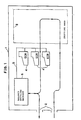
- Fig. 1 is a general layout diagram for the individual machines configured in the transaction processing system according to one preferred embodiment of the present invention. Referring first to Fig. 1, the general constructional features are briefly described.
- a customer enters a store 1 through an entrance door or port 2, and goes on to a shopping area 3, where the customer picks items up as he or she needs.
- a number of ECR's (electronic cash register machines) 4 are located on the exit side of the shopping area 3, and a balance settling machine 8 is located nearer to the entrance or exit port 2.
- This balance settling machine 8 is connected through a data line cable 5 to each of the ECR's 4.
- the customer who has left the shopping area 3 after shopping, goes to any of the ECR's 4, where he or she has the operator record data concerning each of the purchases.
- a magnetic card (which is referred to as "in-house card") on which previously defined class codes and transaction number are magnetically recorded is inserted into the card reader, which reads the class code and transaction number on the magnetic card. After reading, the magnetic card is removed and handed over to the customer. At this time, the transaction data including card data for that customer is sent through the data line 5 to the balance settling machine 6.
- the class code and transaction number on the magnetic card are read by the card reader, and validity checking is made to see whether that magnetic card is valid or not. If there is no problem, a receipt slip is issued, and if the transaction data from the ECR contains any outstanding balance data, the amount of money that is equivalent to that balance data is returned through the outlet to the customer. By now, all transaction processing is completed. For the credited transaction, only a receipt slip is issued.
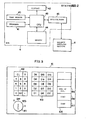
- Fig. 2 is a schematic block diagram for the ECR contained in one preferred embodiment of the present invention.
- the ECR 4 includes a card reader 40, a keyboard 41, a display 42, CPU (Central Processing Unit) 43, a memory 44, and a receive/send interface 45.
- the card reader 40 reads the data on the credit card when the customer wants his or her transaction to be credited, and writes given data on the in-house card which is to be handed to the customer or reads the data from the in-house card.
- the keyboard 41 allows the operator to enter the figures for each of the items purchased by the customer. Its details will be given later by referring to Fig. 3.
- the display 42 indicates the figures for each purchased item and the corresponding group codes as they are entered on the keyboard 41, and the total amount for those figures.
- CPU 43 operates in accordance with the instructions contained in the stored programs, and performs the required registration-related functions.
- the memory 44 is implemented on RAM (random-access memory), for example, which contains data storage areas as shown in Fig. 5. This will be described later.
- the receive/ send interface 45 provides a communication interface to the external balance settling machine 8, through which data from CPU 43 is delivered to the machine 8.
- Fig. 3 illustrates the key arrangement for the keyboard 41, which is a component of the ECR shown in Fig. 2.
- the keyboard 41 includes a mode selector switch 411, a ten-key pad 412, a set of group keys 413, and operation keys 414.
- the mode selector switch 411 allows the operator to select any of the preset mode (P). power off, register mode (REG), and check mode (X) by setting it to the appropriate position.
- the ten-key pad 412 is used to enter numerical data such as price data for each item purchased by the customer.
- Group keys 413 are used to enter the corresponding group codes that have been defined and assigned to each class of goods or services.
- Operation keys 414 include End of Registration key 415, Card key 416, and Cash key 417.
- End of Registration key 415 is used when recording of a transaction data for a given customer is finished.
- Card key 418 is operated when a customer wants his or her transaction to be credited.
- Cash key 417 is used for cash transactions.
- the format of the customer card or in-house card is shown in Fig. 4.
- the customer card or in-house card contains a class code field 50, an account number field 51 , and other fields 52 that are reserved for future use.
- the class code field 50 identifies the type of the card. For example, when this field contains a code of 0, this means the in-house card. Other digit codes imply the customer card.
- the account number field 51 identifies the account number or membership number for the customer card, or the transaction number for the in-house card.
- Fig. 5 illustrates the storage areas in the memory 44 within the ECR 4 shown in Fig. 2, each area providing locations in which the appropriate data is to be stored.
- the storage areas or locations include the work area 441, class code area 442, account number area 443, and transaction area 444.
- the work area 441 serves as a buffer in which data is temporarily held while being processed by CPU 43, which performs arithmetic operations on the data.
- the class code area 442 stores the class code read from the in-house card or customer card.
- the account number area 443 holds the transaction number or account number.
- the transaction area 444 is divided into several sub-areas, in which the corresponding transaction data is held, such as the figures for the customer purchased items or services and the corresponding group codes as entered by the operator on the ECR, the subtotals, the actual amount received, and the amount of any outstanding balance.
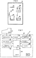
- Fig. 6 shows the front panel of the balance settling machine 8 which is configured as a component of the transaction processing system.
- the front panel contains a card reader 60, a display 64 including two indicators, a change outlet 65, a printer 88, and a receipt suppress key 68, all located as shown in Fig. 6.
- the card reader 60 accepts the customer card or in-house card, and reads the class code and the account number or transaction number recorded on the card.
- the display window indicates the amount of outstanding balance, if any, and the indicator "OK” turns on if the card is valid, while the indicator "NG” turns on if the card is not valid.
- the change outlet 65 returns the balance of money when the customer wants his or her transaction to be paid for in cash and if the amount paid is more than what is due.
- the printer 88 issues a receipt slip.
- the receipt suppress key 88 is used when the customer wants no receipt. When this key is pressed, the printing or issuing is suppressed.
- Fig. 7 illustrates the schematic block diagram of the associated elements within the balance settling machine 8.
- the balance settling machine 6 contains the card reader 80 as previously described in Fig. 8.
- a receive/send interface 81 a memory 62, CPU 83, the display 64, change dispenser 85, printer 66, a telephone line interface 87, and the receipt suppress key 68.
- the receive/send interface 81 connects to the counterpart receive/send interface 45 within the ECR 4 described in Fig. 2, and accepts the various types of data sent from the ECR's.
- the memory 82 is implemented on memory chips such as RAM, and holds the negative file 821 later to be described in Fig. 8 as well as the transaction area 824 as shown in Fig. 9.
- Fig. 8 illustrates the data structure as it is stored in the negative file 821 that is resident in the memory 82 within the balance settling machine 6.
- Fig. 9 shows the data structure as it is similarly stored in the transaction area 824.
- the negative file 821 is used to hold the class code and the account number or transaction number for the customer card or in-house card that is treated as invalid, and contains a class code area 822 and a negative account number area 823.
- the transaction area 624 is used for holding the transaction data received from the ECR 4, and consists of a class code area 825 and an area 828 that holds the account number or transaction number and transaction data which correspond to each class code in the class code area 625.
- Fig. 10 is a flowchart representing the step-by-step operating sequence for the ECR
- Fig. 11 is a flowchart representing the step-by-step operating procedure for the balance settling machine
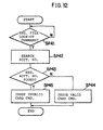
- Fig. 12 is a flowchart that represents the steps to be followed when the the negative file within the the balance settling machine is referenced
- Fig. 13 is a flowchart of the steps to be followed when a transaction using a customer card is processed.
- step SP6 CPU 43 checks that "End of Registration" key 415 has been pressed, and if not, goes back to step SP1. For the remaining items, the above described steps SP1 through SPS are repeated. When all items have been entered, the operator operates the End of Registration key 415. When it is then determined at step SP6 that the End of Registration key has actually been pressed, CPU 43 adds up the figures for all registered items and presents the resulting sub-total on the display 42.
- the operator asks the customer whether the current transaction should be settled on the credit card basis or cash basis. If the customer wants the cash transaction, the operator asks for the amount of money more than or equal to what is due. When he or she receives that amount, the operator enters the data on the amount received by pressing the appropriate keys on the ten-key pad 412. In this case, the Card key 416 is not used. Instead, the operator presses the Cash key 417 in order to identify that the customer is the cash customer.
- CPU 43 checks that the Card key 416 has been operated. If not, CPU 43 proceeds to step SP8, storing the actual amount data as paid and entered on the ten-key pad 412 in the transaction area 444 as the temporarily received amount. At the newt succeeding step SP9, CPU 43 checks that the Cash key 417 has been pressed. If pressed, CPU 43 subtracts the subtotal data from the temporarily received amount data stored in the transaction area 444 to find the balance of money to be returned to the customer. After then, CPU 43 stores the balance data in the transaction area 444 and presents the same data on the display 42.
- the operator After operating the Cash key 417 as described, the operator inserts an in-house card into the card reader 40.
- the information contained in the class code and transaction number fields on the in-house card (Fig. 4) is read from the card reader 40, from which it is passed to CPU 43 for processing (step SP10).
- CPU 43 stores the class code and transaction number information on the in-house card as entered at step SP10 temporarily in the respective areas 442 and 443 within the memory 44.
- the operator removes the in-house card from the card reader and hands it over to the customer.
- an in-house card containing the class code and transaction number information may be issued by the card reader 40, and it may be handed to the customer.
- the action to be taken by the operator is to activate the End of Registration key 415, followed by activating the Card key 416. After activating the Card key 416. which is checked by CPU 43 at step SP7, the operator inserts the customer card into the card reader 40. The class code and account number information contained in the customer card is read by the card reader 40, from which it is passed to CPU 43.
- CPU 43 attempts to determine, at step SP15, whether or not the customer card is valid, based on the information as read from the customer card at step SP14. That is, CPU 43 adds this information as parameters to the negative file look-up command, which is sent to the balance settling machine 8 via the receive/send interface 45.
- CPU 83 proceeds to the negative file look-up routine shown in Fig. 12, based on the negative file look-up command and class code and account number parameters that CPU 83 received from the ECR 4. On entry to this routine.
- CPU 83 initially attempts to determine, at step SP41. whether the negative file look-up command has been entered. If entered, CPU 63 goes further to step SP42, and attempts to scan the negative file 821 that resides in the memory 82 shown in Fig. 8 by using the received class code and account number parameters. At step SP43, an attempt is then made to check whether the approriate negative account number is present. If not found, CPU 83 takes the path (step SP44) to issue a valid card command signal and send it back to the appropriate ECR 4. If found in the negative file 821, step SP45 is taken to issue an invalid card command signal to the ECR 4.
- step SP16 is taken to turn on "NG” indicator. If the valid command signal is received, step SP17 is taken to turn "OK” indicator. In this case, CPU 43 then takes the path SP11, storing the class code and account number information on the cutomer card in the corresponding areas 442 and 443 in the memory 44. Going further to step SP12, CPU 43 retrieves the card data from the respective areas 442 and 443 and the transaction data from the transaction area 444, and send then to the balance settling machine 6. Those series of steps are concluded by clearing all the data associated with the current transaction from the areas 442, 443 and 444 at step SPI3.
- step SP27 is programmed to take the step SP27 in order to determine whether the receipt suppress key 88 has been activated. If not activated, step SP28 is taken to allow CPU 83 to retrieve the data from the transaction data area 824 and send it to the printer 66. Thus, a receipt slip is printed out. If activated, the step SP28 is skipped over to step SP29. At the step SP29, if there is the balance data in the transaction area 624, the amount of money equivalent to that balance data is actually returned to the customer through the change outlet 65. At step SP30 following the SP29, the transaction number and transaction data are cleared from the transaction data area 626. This concludes the steps for the current transaction. 0167860
- step SP31 is taken to allow CPU 83 to search the transaction area 824 for the account number. If the appropriate account number is not found (step SP32), step SP33 is then taken to turn on "NG" indicator. If it is found, the alternative action (step SP34) is taken to check that a receipt slip has already been issued. This is to ensure that a duplicate receipt slip will not be issued for the same customer. If not already issued, step SP35 is followed to cause the "OK" indicator to turn on, and at step SP36 following SP35 the data in the transaction area 824 is sent to the printer 68, from which a receipt slip is printed out.
- Fig. 13 illustrates the data processing flow required for exchanging the credit business data between the balance settling machine 8 and the credit companies. This type of data processing usually occurs during the off-peak hours, such as the night.
- CPU 63 issues an inquiry requesting that each credit company check for the correct account number. This request is transmitted through the telephone line interface 67 and over the telephone network to every credit comapny.
- CPU 83 issues an inquiry command signal. This command signal contains the account number in question that is added as a parameter by CPU 83, and is transmitted to the control center within each credit company. At every control center, searching is made to check whether the account number inquired is valid or not.
- step SP53 the account number and transaction data contained in the area 828 that have been sent are cleared (step SP54), and checking is made to ensure that all data in the transaction area 624 has been sent (step SP58). If not, the same steps as described above are repeated by returning to the step SP51.
- the account number or membership number on an invalid credit card may previously be sent from the control center to CPU 83 so that they can be entered in the negative file 821.
- all transactions may be processed on real-tile online basis as each actually occurs.
- the CPU 43 within the ECR 4 may issue a look-up command signal and send it together with the parameters such as class code, account number and transaction data through its receive/send interface 45 to the balance settling machine 8.
- the CPU 63 within the machine 8 may issue an inquiry signal and send it through its telephone line interface 67 to each credit company control center. If it receives a "valid card” reply to the inquiry, CPU-83 responds with sending the transaction data to the control center for the appropriate credit company, and issues a "normal end" command signal back to the CPU 43 within the ECR 4.
- the CPU 83 sends a "invalid" command signal back to the CPU 43.
- the CPU 43 within the ECR 4 may step to SP17 or SP18. In the real-tile online environment, however, CPU 43 goes from step SP11 directly to step SPI3, bypassing step SP12 for sending transaction data to the balance settling machine 6.
- the subsidiary function is separated from the ECR so that it can be dedicated to the primary function of recording transactions.
- the subsidiary function such as receipt slip printing and balance processing is performed by an independent particular machine, or the balance settling machine 8.
- the operator can be relieved from the extra load, which may result from the subsidiary function.
- a fewer balance settling machines need only to be installed for that number of ECR's.
- the present invention has been shown and described in conjunction with the particular applications such as cash-based or credit card based transactions, those applications may be extended to include the cash card-based transaction.
- the bank account number contained in the cash card may be read by the card reader 40 on ECR 4, and the transaction data including the account number read is sent to the balance settling machine. Then transfer of the transaction data including the account number may occur between the balance settling machine and the bank control center.
Landscapes
- Business, Economics & Management (AREA)
- Physics & Mathematics (AREA)
- General Physics & Mathematics (AREA)
- Accounting & Taxation (AREA)
- Finance (AREA)
- Engineering & Computer Science (AREA)
- Strategic Management (AREA)
- General Business, Economics & Management (AREA)
- Theoretical Computer Science (AREA)
- Economics (AREA)
- Development Economics (AREA)
- Computer Networks & Wireless Communication (AREA)
- Cash Registers Or Receiving Machines (AREA)
- Control Of Vending Devices And Auxiliary Devices For Vending Devices (AREA)
Applications Claiming Priority (2)
| Application Number | Priority Date | Filing Date | Title |
|---|---|---|---|
| JP120497/84 | 1984-06-11 | ||
| JP59120497A JPS60263299A (ja) | 1984-06-11 | 1984-06-11 | 取引処理装置 |
Publications (2)
| Publication Number | Publication Date |
|---|---|
| EP0167860A2 true EP0167860A2 (fr) | 1986-01-15 |
| EP0167860A3 EP0167860A3 (en) | 1988-01-07 |
Family
ID=14787660
Family Applications (1)
| Application Number | Title | Priority Date | Filing Date |
|---|---|---|---|
| EP85107201A Ceased EP0167860A3 (en) | 1984-06-11 | 1985-06-11 | Transaction processing system |
Country Status (3)
| Country | Link |
|---|---|
| US (1) | US4713760A (fr) |
| EP (1) | EP0167860A3 (fr) |
| JP (1) | JPS60263299A (fr) |
Cited By (6)
| Publication number | Priority date | Publication date | Assignee | Title |
|---|---|---|---|---|
| FR2596553A1 (fr) * | 1986-03-27 | 1987-10-02 | Tokyo Electric Co Ltd | Appareil d'enregistrement de donnees de vente |
| WO1989006406A1 (fr) * | 1987-12-28 | 1989-07-13 | Ncr Corporation | Procede et systeme de caisse de sortie |
| US4970681A (en) * | 1986-10-20 | 1990-11-13 | Book Data, Ltd. | Method and apparatus for correlating data |
| US5013896A (en) * | 1987-12-28 | 1991-05-07 | Ncr Corporation | Cashierless checkout system using customer passcard |
| GB2413426A (en) * | 2004-04-19 | 2005-10-26 | Oneempower Pte Ltd | Transaction system |
| EP2549451A1 (fr) * | 2011-07-19 | 2013-01-23 | Glory Ltd. | Système de règlement |
Families Citing this family (31)
| Publication number | Priority date | Publication date | Assignee | Title |
|---|---|---|---|---|
| US5369776A (en) * | 1988-07-14 | 1994-11-29 | Casio Computer Co., Ltd. | Apparatus for producing slips of variable length and having pre-stored word names, and wherein labels are added to word data thereon |
| US5202825A (en) * | 1989-04-28 | 1993-04-13 | Norand Corporation | Transaction control system including portable data terminal and mobile customer service station |
| US5031098A (en) * | 1989-04-28 | 1991-07-09 | Norand Corporation | Transaction control system including portable data terminal and mobile customer service station |
| US5263164A (en) | 1991-01-09 | 1993-11-16 | Verifone, Inc. | Method and structure for determining transaction system hardware and software configurations |
| JP3064710B2 (ja) * | 1992-12-11 | 2000-07-12 | 富士通株式会社 | データ処理システム |
| EP0810564B1 (fr) * | 1996-05-31 | 2003-04-23 | Hitachi, Ltd. | Dispositif pour stocker de la monnaie électronique et méthode de commande avec carte à puce |
| US7555458B1 (en) | 1996-06-05 | 2009-06-30 | Fraud Control System.Com Corporation | Method of billing a purchase made over a computer network |
| US20030195847A1 (en) | 1996-06-05 | 2003-10-16 | David Felger | Method of billing a purchase made over a computer network |
| US8229844B2 (en) | 1996-06-05 | 2012-07-24 | Fraud Control Systems.Com Corporation | Method of billing a purchase made over a computer network |
| AU763571B2 (en) | 1998-12-23 | 2003-07-24 | Chase Manhattan Bank, The | System and method for integrating trading operations including the generation, processing and tracking of and trade documents |
| JP2000207646A (ja) * | 1999-01-08 | 2000-07-28 | Ncr Internatl Inc | マルチポイント入力式posシステム |
| US6408279B1 (en) | 1999-06-28 | 2002-06-18 | Ncr Corporation | Method and apparatus for operating a self-service checkout terminal and a remote supervisor terminal of a retail system |
| JP3930209B2 (ja) * | 1999-10-20 | 2007-06-13 | 富士通株式会社 | 取引管理装置及び方法並びに取引管理プログラムを格納したコンピュータ可読の記録媒体 |
| US8793160B2 (en) | 1999-12-07 | 2014-07-29 | Steve Sorem | System and method for processing transactions |
| US7831467B1 (en) | 2000-10-17 | 2010-11-09 | Jpmorgan Chase Bank, N.A. | Method and system for retaining customer loyalty |
| US8849716B1 (en) | 2001-04-20 | 2014-09-30 | Jpmorgan Chase Bank, N.A. | System and method for preventing identity theft or misuse by restricting access |
| AU2002312381A1 (en) | 2001-06-07 | 2002-12-16 | First Usa Bank, N.A. | System and method for rapid updating of credit information |
| US7266839B2 (en) | 2001-07-12 | 2007-09-04 | J P Morgan Chase Bank | System and method for providing discriminated content to network users |
| AUPR647701A0 (en) * | 2001-07-19 | 2001-08-09 | Synkronos Pty Ltd | Virtual credit card terminal and method of transaction |
| US8020754B2 (en) | 2001-08-13 | 2011-09-20 | Jpmorgan Chase Bank, N.A. | System and method for funding a collective account by use of an electronic tag |
| US7987501B2 (en) | 2001-12-04 | 2011-07-26 | Jpmorgan Chase Bank, N.A. | System and method for single session sign-on |
| US20040122736A1 (en) | 2002-10-11 | 2004-06-24 | Bank One, Delaware, N.A. | System and method for granting promotional rewards to credit account holders |
| US8301493B2 (en) | 2002-11-05 | 2012-10-30 | Jpmorgan Chase Bank, N.A. | System and method for providing incentives to consumers to share information |
| US8306907B2 (en) | 2003-05-30 | 2012-11-06 | Jpmorgan Chase Bank N.A. | System and method for offering risk-based interest rates in a credit instrument |
| US8175908B1 (en) | 2003-09-04 | 2012-05-08 | Jpmorgan Chase Bank, N.A. | Systems and methods for constructing and utilizing a merchant database derived from customer purchase transactions data |
| US7401731B1 (en) | 2005-05-27 | 2008-07-22 | Jpmorgan Chase Bank, Na | Method and system for implementing a card product with multiple customized relationships |
| US7925578B1 (en) | 2005-08-26 | 2011-04-12 | Jpmorgan Chase Bank, N.A. | Systems and methods for performing scoring optimization |
| US8622308B1 (en) | 2007-12-31 | 2014-01-07 | Jpmorgan Chase Bank, N.A. | System and method for processing transactions using a multi-account transactions device |
| US8554652B1 (en) | 2008-02-21 | 2013-10-08 | Jpmorgan Chase Bank, N.A. | System and method for providing borrowing schemes |
| US8554631B1 (en) | 2010-07-02 | 2013-10-08 | Jpmorgan Chase Bank, N.A. | Method and system for determining point of sale authorization |
| US9058626B1 (en) | 2013-11-13 | 2015-06-16 | Jpmorgan Chase Bank, N.A. | System and method for financial services device usage |
Family Cites Families (13)
| Publication number | Priority date | Publication date | Assignee | Title |
|---|---|---|---|---|
| CH434633A (de) * | 1965-11-26 | 1967-04-30 | Aeberhard Fritz | Kassierstand für Selbstbedienungsgeschäfte |
| DE1549364A1 (de) * | 1967-03-21 | 1969-10-23 | Zschaeck Herbert Karl | Dateneingabevorrichtung in Verbindung mit einer Muenzausgabevorrichtung |
| JPS5839349B2 (ja) * | 1979-03-27 | 1983-08-29 | ロ−レルバンクマシン株式会社 | レジスタ装置 |
| US4570223A (en) * | 1979-10-12 | 1986-02-11 | Sharp Kabushiki Kaisha | Cash register control system for authorization of selected operator functions |
| US4317957A (en) * | 1980-03-10 | 1982-03-02 | Marvin Sendrow | System for authenticating users and devices in on-line transaction networks |
| JPS5790777A (en) * | 1980-11-26 | 1982-06-05 | Sharp Corp | Electronic cash register |
| JPS58189768A (ja) * | 1982-04-28 | 1983-11-05 | Omron Tateisi Electronics Co | 電子式キヤツシユレジスタシステム |
| SE8202970L (sv) * | 1982-05-12 | 1983-11-13 | Lundblad Leif | For butik avsedd inredning |
| JPS58222373A (ja) * | 1982-06-18 | 1983-12-24 | Sharp Corp | 金銭出納システム |
| JPS5924371A (ja) * | 1982-07-30 | 1984-02-08 | Sharp Corp | 電子レジスタ |
| JPS59154572A (ja) * | 1983-02-23 | 1984-09-03 | Omron Tateisi Electronics Co | 取引決済装置 |
| JPH079678B2 (ja) * | 1983-03-01 | 1995-02-01 | オムロン株式会社 | 電子式キヤツシユ・レジスタ |
| US4650978A (en) * | 1985-01-23 | 1987-03-17 | Rmh Systems, Inc. | Off line cash card system and method |
-
1984
- 1984-06-11 JP JP59120497A patent/JPS60263299A/ja active Pending
-
1985
- 1985-06-11 EP EP85107201A patent/EP0167860A3/en not_active Ceased
- 1985-06-11 US US06/743,398 patent/US4713760A/en not_active Expired - Fee Related
Cited By (9)
| Publication number | Priority date | Publication date | Assignee | Title |
|---|---|---|---|---|
| FR2596553A1 (fr) * | 1986-03-27 | 1987-10-02 | Tokyo Electric Co Ltd | Appareil d'enregistrement de donnees de vente |
| US4893237A (en) * | 1986-03-27 | 1990-01-09 | Tokyo Electric Co., Ltd. | Interconnected sales data registration and payment settlement system |
| US4970681A (en) * | 1986-10-20 | 1990-11-13 | Book Data, Ltd. | Method and apparatus for correlating data |
| WO1989006406A1 (fr) * | 1987-12-28 | 1989-07-13 | Ncr Corporation | Procede et systeme de caisse de sortie |
| US5013896A (en) * | 1987-12-28 | 1991-05-07 | Ncr Corporation | Cashierless checkout system using customer passcard |
| GB2413426A (en) * | 2004-04-19 | 2005-10-26 | Oneempower Pte Ltd | Transaction system |
| GB2413426B (en) * | 2004-04-19 | 2006-10-18 | Oneempower Pte Ltd | Transaction system |
| EP2549451A1 (fr) * | 2011-07-19 | 2013-01-23 | Glory Ltd. | Système de règlement |
| US10062065B2 (en) | 2011-07-19 | 2018-08-28 | Glory Ltd. | Settlement system |
Also Published As
| Publication number | Publication date |
|---|---|
| US4713760A (en) | 1987-12-15 |
| JPS60263299A (ja) | 1985-12-26 |
| EP0167860A3 (en) | 1988-01-07 |
Similar Documents
| Publication | Publication Date | Title |
|---|---|---|
| US4713760A (en) | Transaction processing system for separate registration and settlement functions | |
| US5352876A (en) | Method and apparatus for transaction settlement | |
| EP0098593B1 (fr) | Système pour le traitement de transactions à crédit | |
| EP0681248B1 (fr) | Equipement terminal, méthode et média pour la gestion de clients | |
| WO2002017175A1 (fr) | Procede de paiement par carte pour facturation de service concernant une distribution ou un transport physiques | |
| JPH0589372A (ja) | 商品販売データ処理装置 | |
| JP2509995B2 (ja) | クレジット端末機 | |
| JP3063195B2 (ja) | 記憶カードによる取引点数管理システム | |
| JP2952118B2 (ja) | クレジット処理装置 | |
| JP2703940B2 (ja) | カード取引処理装置 | |
| JP3410740B2 (ja) | Icカード | |
| JPH0855167A (ja) | ポイント購入処理方法及びポイントサービスシステム | |
| JPH087053A (ja) | 商品情報管理システム | |
| JPH10124592A (ja) | 取引処理システム | |
| JP2573698B2 (ja) | 商品販売データ処理装置 | |
| JP2542732B2 (ja) | 取引処理装置 | |
| JP3076685B2 (ja) | 商品販売データ処理装置 | |
| JP2938783B2 (ja) | キャッシュカード決済システム | |
| JPS63175997A (ja) | 電子式キヤツシユレジスタ | |
| JP3285113B2 (ja) | 金銭登録装置およびそのカード取引処理方法 | |
| JPH06243350A (ja) | 商品販売データ処理装置 | |
| JPH0652370A (ja) | プリペイドカード決済装置 | |
| JP2539925B2 (ja) | カ―ド取引装置 | |
| EP1248212A1 (fr) | Dispositif central, terminal, dispositif de supervision de systeme d'utilisateur, procede de commande de ces dispositifs et support d'enregistrement de programme | |
| JPS62191999A (ja) | 電子式キヤツシユレジスタ |
Legal Events
| Date | Code | Title | Description |
|---|---|---|---|
| PUAI | Public reference made under article 153(3) epc to a published international application that has entered the european phase |
Free format text: ORIGINAL CODE: 0009012 |
|
| 17P | Request for examination filed |
Effective date: 19850611 |
|
| AK | Designated contracting states |
Designated state(s): AT BE CH DE FR GB IT LI LU NL SE |
|
| PUAL | Search report despatched |
Free format text: ORIGINAL CODE: 0009013 |
|
| AK | Designated contracting states |
Kind code of ref document: A3 Designated state(s): AT BE CH DE FR GB IT LI LU NL SE |
|
| 17Q | First examination report despatched |
Effective date: 19900323 |
|
| STAA | Information on the status of an ep patent application or granted ep patent |
Free format text: STATUS: THE APPLICATION HAS BEEN REFUSED |
|
| 18R | Application refused |
Effective date: 19911010 |
|
| RIN1 | Information on inventor provided before grant (corrected) |
Inventor name: YAMAGUCHI, TAKAO Inventor name: YAMADA, KAZUTOSHI |