EP0167892A1 - Cartouche pour ruban encreur - Google Patents
Cartouche pour ruban encreur Download PDFInfo
- Publication number
- EP0167892A1 EP0167892A1 EP19850107531 EP85107531A EP0167892A1 EP 0167892 A1 EP0167892 A1 EP 0167892A1 EP 19850107531 EP19850107531 EP 19850107531 EP 85107531 A EP85107531 A EP 85107531A EP 0167892 A1 EP0167892 A1 EP 0167892A1
- Authority
- EP
- European Patent Office
- Prior art keywords
- inked ribbon
- ink
- ribbon cassette
- replenisher
- container
- Prior art date
- Legal status (The legal status is an assumption and is not a legal conclusion. Google has not performed a legal analysis and makes no representation as to the accuracy of the status listed.)
- Granted
Links
Images



Classifications
-
- B—PERFORMING OPERATIONS; TRANSPORTING
- B41—PRINTING; LINING MACHINES; TYPEWRITERS; STAMPS
- B41J—TYPEWRITERS; SELECTIVE PRINTING MECHANISMS, i.e. MECHANISMS PRINTING OTHERWISE THAN FROM A FORME; CORRECTION OF TYPOGRAPHICAL ERRORS
- B41J31/00—Ink ribbons; Renovating or testing ink ribbons
- B41J31/14—Renovating or testing ink ribbons
- B41J31/16—Renovating or testing ink ribbons while fitted in the machine using the ink ribbons
-
- B—PERFORMING OPERATIONS; TRANSPORTING
- B41—PRINTING; LINING MACHINES; TYPEWRITERS; STAMPS
- B41J—TYPEWRITERS; SELECTIVE PRINTING MECHANISMS, i.e. MECHANISMS PRINTING OTHERWISE THAN FROM A FORME; CORRECTION OF TYPOGRAPHICAL ERRORS
- B41J32/00—Ink-ribbon cartridges
- B41J32/02—Ink-ribbon cartridges for endless ribbons
Definitions
- the present invention relates to an inked ribbon cassette for being mounted on a printer carriage, and more particularly to an inked ribbon cassette having an ink replenisher for replenishing the inked ribbon with ink.
- the disclosed inked ribbon cassette includes an inked ribbon storage space partitioned to provide a chamber in which an ink cartridge is disposed.
- the ink cartridge supplies ink to a drive roller for driving the inked ribbon in a circulatory manner. since the drive roller is held in contact with the inked ribbon, the ink supplied to the drive roller is fed to the inked ribbon.
- the inked ribbon is of an endless configuration with a substantial length thereof being folded in the inked ribbon storage space.
- the inked ribbon is delivered from the storage space through one guide arm to an exposed portion where the inked ribbon can contact a print head.
- the inked ribbon at the exposed portion has been pressed against a sheet of print paper by the print head to transfer ink to the sheet, the inked ribbon is passed through the other guide arm back into the storage space. This circulatory feeding process is repeated each time a printing operation is effected.
- the ink in the inked ribbon is reduced in amount right after it has been printed. However, since ink is supplied from the ink cartridge, the inked ribbon has a longer service life than would otherwise have.
- the ink cartridge stores a small amount of ink because it is housed in the chamber in the inked ribbon storage space within the cassette. If a greater amount of ink were to be stored, then the inked ribbon cassette would be increased in size. The larger-size inked ribbon cassette would take up a larger installation space or impair an installation efficiency, and make it difficult to design a smaller and lighter printer.
- Another object of the present invention is to provide an inked ribbon cassette having an improved installation efficiency.
- Still another object of the present invention is to provide an inked ribbon cassette having an inked ribbon of an increased service life.
- an inked ribbon cassette according to the present invention comprises an inked ribbon, a container having an inked ribbon storage space in which the ink ribbon is stored, a drive roller for circulating the inked ribbon, a follower roller pressed against the driver roller for sandwiching the inked ribbon therebetween, an ink replenisher formed integrally out of the container and sharing one wall with the container, and a projection extending from the ink replenisher into contact with the follower roller for supplying ink from the ink replenisher through the follower roller to the inked ribbon.
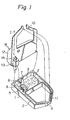
- Fig. 1 shows an inked ribbon cassette according to a first embodiment of the present invention.
- the inked ribbon cassette includes an inked ribbon cassette body 1 having an inked ribbon storage space 3 in which a substantial length of an inked ribbon 2 is stored, with one end of the inked ribbon 2 being exposed at a distal end portion 4.
- the inked ribbon 2 is gripped between . a drive roller 5 and a follower roller 6 pressed against the drive roller 5, the rollers 5, 6 being disposed in the inked ribbon storage space 3.
- the follower roller 6 is supported on a movable support member 7 which is normally urged by a spring 8 in a direction to push the follower roller 6 against the drive roller 5.
- the inked ribbon cassette is mounted on a printer carriage (not shown).
- the drive roller 5 is rotated about its own axis in the direction of the arrow by a drive force which is derived from the movement of the carriage in a character-spacing direction.
- the inked ribbon cassette also includes an ink replenisher 9 doubling as a cover for the inked ribbon cassette body 1 and has a plurality of engagement pins 10 which fit respectively in holes 11 defined in the inked ribbon cassette body 1 to anchor the ink replenisher 9 thereon.
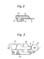
- the ink replenisher 9 has a hollow portion 12 containing therein an ink-impregnated body 15 (Fig. 2) such as a porous member such as a body of sponge or a fibrous member such as a body of felt that is impregnated with ink.
- a projection 14 impregnated with ink extends from a projecting block 13 formed on the hollow portion 12. The projection 14 is positioned for contacting the follower roller 6 when the ink replenisher 9 is fixedly mounted on the ink ribbon cassette body 1.
- Fig. 3 shows the manner in which the inked ribbon cassette is mounted on a printer carriage.
- the inked ribbon cassette mounted on the printer carriage, designated at 30, is disposed in surrounding relation to a print head 32, with the inked ribbon 2 being supplied between the print head 32 and a platen 34.
- the inked ribbon 2 lies and travels in a vertical zone indicated at W
- the hollow portion 12 of the ink replenisher 9 lies in a vertical zone indicated at L above the vertical zone W . Therefore, a space above the inked ribbon 2, which would otherwise be left empty is effectively employed as the vertical zone L for the hollow portion 12.
- Fig. 4 shows an inked ribbon cassette according to a second embodiment of the present invention. Like or corresponding parts in Fig. 4 are denoted by like or corresponding reference characters in Fig. 1.
- an ink replenisher is mounted on an inked ribbon cassette body 1, rather than on a cover 40.
- the ink replenisher has a projecting block 41 integral with the inked ribbon cassette body 1, so that the block 41 and a follower roller 6 will not be subjected to a relative positional displacement which would otherwise be caused by a manufacturing error.
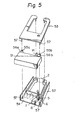
- Fig. 5 illustrates an inked ribbon cassette according to a third embodiment of the present invention. Like or corresponding parts in Fig. 5 are denoted by like or corresponding reference characters in Fig. 1.
- an ink replenisher 51 has a thickness equal to that of a container composed of an inked ribbon cassette body 52 and a cover 53, the ink replenisher 51 being attached to the rear end of an inked ribbon storage space 54.
- the ink replenisher 51 has attachment arms 56a, 56b having respective holes 55a, 55b and positioned on the opposite ends of one side thereof, from which a projection 14 extends laterally.
- the inked ribbon cassette body 52 and the cover 53 have pins 57 which fit in the holes 55a, 55b to join the body 52, the cover 53, and the ink replenisher 51 together.
- the projection 14 is held in contact with the followerroller 6.
- Fig. 6 shows an inked ribbon cassette according to a fourth embodiment of the present invention. Like or corresponding parts in Fig. 6 are denoted by like or corresponding reference characters in Fig. 5.
- the inked ribbon cassette shown in Fig. 6 is basically of the same construction as that of the inked ribbon cassette illustrated in Fig. 5, except that a follower roller 61 and a movable support member 62 therefor are mounted on the side of an ink replenisher 60 to which attachment arms 56a, 56b are attached.
- the movable support member 62 is integrally formed with the ink replenisher 60, and is molded of a plastic material such as polyacetal for example.
- the movable support member 62 includes a resilient portion 62a having a thickness ranging from 0.5 to 1 mm for making the support member 62 springy so as to keep the follower roller 61 resilient against a projection 14.
- the other structural detail of Fig. 6 are the same as those ' of Fig. 5 and will not be described.
- Fig. 7 illustrates an inked ribbon cassette according to a fifth embodiment of the present invention.
- the inked ribbon cassette of Fig. 7 is in fact a modification of the fourth embodiment.
- An ink replenisher 70 has a support member 71 attached to an end thereof such that the ink replenisher 70 is angularly movable about the support member 71 with respect to an inked ribbon casse tte : body.
- a spring 73 acts on the end of the ink replenisher 70 remote from the support member 71 for normally urging the ink replenisher 70 in a direction to press a follower roller 6 against a drive roller 5.
- the thickness of the container of the ink replenisher can be identical to the thickness of the container of the inked ribbon cassette body, so that the ink replenisher is increased in size up to the thickness of the container of the inked ribbon cassette body. Therefore, the service life of the inked ribbon can be prolonged for allowing the inked ribbon cassette to be used for a longer period of time.
- the ink replenisher Since the ink replenisher is positioned out of the inked ribbon cassette body, it does not reduce the capacity of the inked ribbon storage space in the inked ribbon cassette body.
Landscapes
- Impression-Transfer Materials And Handling Thereof (AREA)
Applications Claiming Priority (6)
| Application Number | Priority Date | Filing Date | Title |
|---|---|---|---|
| JP8938184U JPS615665U (ja) | 1984-06-18 | 1984-06-18 | インクリボンカセツト |
| JP89381/84U | 1984-06-18 | ||
| JP8938084U JPS615664U (ja) | 1984-06-18 | 1984-06-18 | インクリボンカセツト |
| JP89380/84U | 1984-06-18 | ||
| JP93779/84U | 1984-06-25 | ||
| JP9377984U JPS6110857U (ja) | 1984-06-25 | 1984-06-25 | インクリボンカセツト |
Publications (2)
| Publication Number | Publication Date |
|---|---|
| EP0167892A1 true EP0167892A1 (fr) | 1986-01-15 |
| EP0167892B1 EP0167892B1 (fr) | 1990-03-07 |
Family
ID=27306100
Family Applications (1)
| Application Number | Title | Priority Date | Filing Date |
|---|---|---|---|
| EP19850107531 Expired EP0167892B1 (fr) | 1984-06-18 | 1985-06-18 | Cartouche pour ruban encreur |
Country Status (4)
| Country | Link |
|---|---|
| EP (1) | EP0167892B1 (fr) |
| DE (1) | DE3576302D1 (fr) |
| HK (1) | HK92492A (fr) |
| SG (1) | SG61592G (fr) |
Cited By (9)
| Publication number | Priority date | Publication date | Assignee | Title |
|---|---|---|---|---|
| DE3530659A1 (de) * | 1985-08-28 | 1987-03-12 | Turbon Plastic Gmbh | Farbbandkassette mit einer nachtraenkeinheit |
| DE3535876A1 (de) * | 1985-10-08 | 1987-04-09 | Turbon International | Farbbandkassette fuer gestopfte endlosfarbbaender |
| US4747711A (en) * | 1986-02-28 | 1988-05-31 | Ing. C. Olivetti & C., S.P.A. | Cartridge for an inked ribbon with a re-inking device |
| EP0391836A3 (fr) * | 1989-04-05 | 1991-02-27 | Heinz Kruschinski | Cassette à ruban encreur |
| GB2246760A (en) * | 1990-08-10 | 1992-02-12 | Hitachi Powdered Metals | Ink ribbon cassette: inking roll |
| EP0526119A3 (fr) * | 1991-07-30 | 1993-04-21 | Yiu-Wah Chow | Cassette ruban pour imprimante |
| US5207519A (en) * | 1991-01-14 | 1993-05-04 | Debreczenyi Frank M | Re-inkable method and arrangement for printer ribbons |
| WO1994025280A1 (fr) * | 1993-04-30 | 1994-11-10 | Debreczenyi Frank M | Ameliorations relatives a des cartouches d'encre |
| WO2022263034A1 (fr) | 2022-03-29 | 2022-12-22 | Haag-Streit Ag | Périmètre à objectif réglable |
Citations (2)
| Publication number | Priority date | Publication date | Assignee | Title |
|---|---|---|---|---|
| US4153378A (en) * | 1975-11-18 | 1979-05-08 | Franz Buttner Ag. | Re-inking and ventilation control for inked ribbon cassette |
| DE2939344A1 (de) * | 1978-10-03 | 1980-04-17 | Honeywell Inf Systems | Farbbandkassette |
-
1985
- 1985-06-18 EP EP19850107531 patent/EP0167892B1/fr not_active Expired
- 1985-06-18 DE DE8585107531T patent/DE3576302D1/de not_active Expired - Lifetime
-
1992
- 1992-06-15 SG SG61592A patent/SG61592G/en unknown
- 1992-11-19 HK HK92492A patent/HK92492A/en not_active IP Right Cessation
Patent Citations (2)
| Publication number | Priority date | Publication date | Assignee | Title |
|---|---|---|---|---|
| US4153378A (en) * | 1975-11-18 | 1979-05-08 | Franz Buttner Ag. | Re-inking and ventilation control for inked ribbon cassette |
| DE2939344A1 (de) * | 1978-10-03 | 1980-04-17 | Honeywell Inf Systems | Farbbandkassette |
Cited By (11)
| Publication number | Priority date | Publication date | Assignee | Title |
|---|---|---|---|---|
| DE3530659A1 (de) * | 1985-08-28 | 1987-03-12 | Turbon Plastic Gmbh | Farbbandkassette mit einer nachtraenkeinheit |
| DE3535876A1 (de) * | 1985-10-08 | 1987-04-09 | Turbon International | Farbbandkassette fuer gestopfte endlosfarbbaender |
| US4747711A (en) * | 1986-02-28 | 1988-05-31 | Ing. C. Olivetti & C., S.P.A. | Cartridge for an inked ribbon with a re-inking device |
| EP0391836A3 (fr) * | 1989-04-05 | 1991-02-27 | Heinz Kruschinski | Cassette à ruban encreur |
| GB2246760A (en) * | 1990-08-10 | 1992-02-12 | Hitachi Powdered Metals | Ink ribbon cassette: inking roll |
| GB2246760B (en) * | 1990-08-10 | 1994-05-11 | Hitachi Powdered Metals | Ink ribbon cassette |
| US5207519A (en) * | 1991-01-14 | 1993-05-04 | Debreczenyi Frank M | Re-inkable method and arrangement for printer ribbons |
| US5401108A (en) * | 1991-01-14 | 1995-03-28 | Debreczenyi; Frank M. | Ink retaining mass for reinking ribbons in ink cartridges |
| EP0526119A3 (fr) * | 1991-07-30 | 1993-04-21 | Yiu-Wah Chow | Cassette ruban pour imprimante |
| WO1994025280A1 (fr) * | 1993-04-30 | 1994-11-10 | Debreczenyi Frank M | Ameliorations relatives a des cartouches d'encre |
| WO2022263034A1 (fr) | 2022-03-29 | 2022-12-22 | Haag-Streit Ag | Périmètre à objectif réglable |
Also Published As
| Publication number | Publication date |
|---|---|
| HK92492A (en) | 1992-11-27 |
| EP0167892B1 (fr) | 1990-03-07 |
| DE3576302D1 (de) | 1990-04-12 |
| SG61592G (en) | 1992-09-04 |
Similar Documents
| Publication | Publication Date | Title |
|---|---|---|
| EP0153388B1 (fr) | Cassette a ruban pour imprimante | |
| EP0167892B1 (fr) | Cartouche pour ruban encreur | |
| US4838718A (en) | Printing device | |
| US4747713A (en) | Ink ribbon cassette including gear teeth configured to re-ink the ribbon | |
| US4741640A (en) | Ink ribbon cartridge of a printing machine | |
| EP0398452B1 (fr) | Réservoir d'encre pour une tête d'impression matricielle par points à aguilles | |
| US4690576A (en) | Automatic ribbon re-inker | |
| EP0406982B1 (fr) | Procédé d'imprégnation d'absorbeurs d'encre | |
| JPH0410067Y2 (fr) | ||
| JPH0324371Y2 (fr) | ||
| JPH0536705Y2 (fr) | ||
| GB2033872A (en) | Reinking of endless ink ribbon cartridges | |
| JPS6323166Y2 (fr) | ||
| JP2578761Y2 (ja) | インクリボンカートリッジに於けるインク補給装置 | |
| JPH04220382A (ja) | リボンカセットのインク補給機構 | |
| JPS60291Y2 (ja) | インクリボンカートリツジ | |
| JPS62248677A (ja) | インクリボンカ−トリツジ | |
| US5195834A (en) | Ink ribbon cassette | |
| JP3075845B2 (ja) | インクジェットプリンタの用紙排出装置 | |
| JPH0368837B2 (fr) | ||
| JPH0541832U (ja) | リボンカセツト | |
| JPS5837654Y2 (ja) | エンドレスインクリボンカ−トリツジ | |
| JPS582607Y2 (ja) | 小型印字装置 | |
| JPH06206362A (ja) | インクリボンカセット | |
| JPH0234379A (ja) | インクリボンカセット |
Legal Events
| Date | Code | Title | Description |
|---|---|---|---|
| PUAI | Public reference made under article 153(3) epc to a published international application that has entered the european phase |
Free format text: ORIGINAL CODE: 0009012 |
|
| AK | Designated contracting states |
Designated state(s): DE GB IT |
|
| 17P | Request for examination filed |
Effective date: 19860715 |
|
| 17Q | First examination report despatched |
Effective date: 19880629 |
|
| GRAA | (expected) grant |
Free format text: ORIGINAL CODE: 0009210 |
|
| AK | Designated contracting states |
Kind code of ref document: B1 Designated state(s): DE GB IT |
|
| REF | Corresponds to: |
Ref document number: 3576302 Country of ref document: DE Date of ref document: 19900412 |
|
| ITF | It: translation for a ep patent filed | ||
| PLBE | No opposition filed within time limit |
Free format text: ORIGINAL CODE: 0009261 |
|
| STAA | Information on the status of an ep patent application or granted ep patent |
Free format text: STATUS: NO OPPOSITION FILED WITHIN TIME LIMIT |
|
| 26N | No opposition filed | ||
| ITTA | It: last paid annual fee | ||
| REG | Reference to a national code |
Ref country code: GB Ref legal event code: IF02 |
|
| PGFP | Annual fee paid to national office [announced via postgrant information from national office to epo] |
Ref country code: GB Payment date: 20040616 Year of fee payment: 20 |
|
| PGFP | Annual fee paid to national office [announced via postgrant information from national office to epo] |
Ref country code: DE Payment date: 20040701 Year of fee payment: 20 |
|
| PG25 | Lapsed in a contracting state [announced via postgrant information from national office to epo] |
Ref country code: GB Free format text: LAPSE BECAUSE OF EXPIRATION OF PROTECTION Effective date: 20050617 |
|
| REG | Reference to a national code |
Ref country code: GB Ref legal event code: PE20 |