EP0167955B1 - Plasmabeutel - Google Patents
Plasmabeutel Download PDFInfo
- Publication number
- EP0167955B1 EP0167955B1 EP85108139A EP85108139A EP0167955B1 EP 0167955 B1 EP0167955 B1 EP 0167955B1 EP 85108139 A EP85108139 A EP 85108139A EP 85108139 A EP85108139 A EP 85108139A EP 0167955 B1 EP0167955 B1 EP 0167955B1
- Authority
- EP
- European Patent Office
- Prior art keywords
- bag
- line
- weakness
- plasma
- break
- Prior art date
- Legal status (The legal status is an assumption and is not a legal conclusion. Google has not performed a legal analysis and makes no representation as to the accuracy of the status listed.)
- Expired - Lifetime
Links
- 239000000463 material Substances 0.000 claims abstract description 22
- 238000012546 transfer Methods 0.000 claims abstract description 16
- 239000004698 Polyethylene Substances 0.000 claims description 3
- -1 polyethylene Polymers 0.000 claims description 3
- 229920000573 polyethylene Polymers 0.000 claims description 3
- 229920000915 polyvinyl chloride Polymers 0.000 claims description 3
- 239000004800 polyvinyl chloride Substances 0.000 claims description 3
- 230000002787 reinforcement Effects 0.000 description 9
- 238000011109 contamination Methods 0.000 description 8
- 238000000034 method Methods 0.000 description 7
- 230000000813 microbial effect Effects 0.000 description 5
- 230000003014 reinforcing effect Effects 0.000 description 4
- 238000013461 design Methods 0.000 description 3
- 238000004519 manufacturing process Methods 0.000 description 3
- 238000012545 processing Methods 0.000 description 3
- 238000005194 fractionation Methods 0.000 description 2
- 238000001802 infusion Methods 0.000 description 2
- 239000004033 plastic Substances 0.000 description 2
- 229920003023 plastic Polymers 0.000 description 2
- 239000000725 suspension Substances 0.000 description 2
- 238000010257 thawing Methods 0.000 description 2
- 238000003466 welding Methods 0.000 description 2
- LFQSCWFLJHTTHZ-UHFFFAOYSA-N Ethanol Chemical compound CCO LFQSCWFLJHTTHZ-UHFFFAOYSA-N 0.000 description 1
- 102000001690 Factor VIII Human genes 0.000 description 1
- 108010054218 Factor VIII Proteins 0.000 description 1
- 239000008280 blood Substances 0.000 description 1
- 210000004369 blood Anatomy 0.000 description 1
- 239000010836 blood and blood product Substances 0.000 description 1
- 229940125691 blood product Drugs 0.000 description 1
- 238000004140 cleaning Methods 0.000 description 1
- 230000007717 exclusion Effects 0.000 description 1
- 229960000301 factor viii Drugs 0.000 description 1
- 230000008014 freezing Effects 0.000 description 1
- 238000007710 freezing Methods 0.000 description 1
- 238000010348 incorporation Methods 0.000 description 1
- 238000011835 investigation Methods 0.000 description 1
- 238000012423 maintenance Methods 0.000 description 1
- 230000002906 microbiologic effect Effects 0.000 description 1
- 239000008188 pellet Substances 0.000 description 1
- 239000004014 plasticizer Substances 0.000 description 1
- 238000002360 preparation method Methods 0.000 description 1
- 230000002265 prevention Effects 0.000 description 1
- 102000004169 proteins and genes Human genes 0.000 description 1
- 108090000623 proteins and genes Proteins 0.000 description 1
- 230000001698 pyrogenic effect Effects 0.000 description 1
- 238000007789 sealing Methods 0.000 description 1
- 238000000926 separation method Methods 0.000 description 1
- 238000010008 shearing Methods 0.000 description 1
- 239000007921 spray Substances 0.000 description 1
- 238000003860 storage Methods 0.000 description 1
- 230000001225 therapeutic effect Effects 0.000 description 1
Images


Classifications
-
- A—HUMAN NECESSITIES
- A61—MEDICAL OR VETERINARY SCIENCE; HYGIENE
- A61J—CONTAINERS SPECIALLY ADAPTED FOR MEDICAL OR PHARMACEUTICAL PURPOSES; DEVICES OR METHODS SPECIALLY ADAPTED FOR BRINGING PHARMACEUTICAL PRODUCTS INTO PARTICULAR PHYSICAL OR ADMINISTERING FORMS; DEVICES FOR ADMINISTERING FOOD OR MEDICINES ORALLY; BABY COMFORTERS; DEVICES FOR RECEIVING SPITTLE
- A61J1/00—Containers specially adapted for medical or pharmaceutical purposes
- A61J1/05—Containers specially adapted for medical or pharmaceutical purposes for collecting, storing or administering blood, plasma or medical fluids ; Infusion or perfusion containers
- A61J1/10—Bag-type containers
Definitions
- the present invention relates to plasma bags which can be removed from frozen plasma without contamination.
- the invention is directed to a plasma transfer bag of flexible, sterilizable material, the bag having two side walls and being closed at the base, the bag further having an extension to the base for gripping or holding the bag, the extension flap having a break therein extending to the base of the bag and the bag having a line of weakness in the walls extending from the break to the top of the bag.
- a plasma bag of this type is described in EP-A-0,076,062.
- All blood products should be demonstrably non-pyrogenic and effort is necessary to monitor and control the microbial levels (particularly of gram-negative organisms) as each stage of the fractionation process. To this end, the microbial levels are monitored throughout processing.
- GB-A-2,133,383 published after the priority date of the present application, attempts to fulfill those requirements by providing a plasma transfer bag for containing plasma.
- the bag being made from translucent flexible, sterilizable material, the bag being closed at the bottom and having an extension in which there are means for gripping or holding the bag, the extension flap additionally having a break which may allow the bag to be split from the break up to the top of the bag when the extension is gripped either side of the notch.
- the bag as described in our earlier application GB-A-2,133,383 fulfills the requirements.
- one of the problems that does occur with the bag is lack of uniform tearing of the bag on lateral tearing at the corners.
- the lack of uniformity in tearing can cause the frozen plasma to eject from the bag in an uncontrollable manner.
- the present invention attempts to overcome this problem.
- a plasma transfer bag of the type as described in the introductory part of the specification the bag on each side of the line of weakness being reinforced at least adjacent the base to control tearing of the bag from the base to the top of the bag when opposing forces are applied to the extension in a transverse direction parallel to the base of the bag to cause the bag to split and eject the contents.
- the bag is made from two sheets of flexible material which is flexible at -40°C, the sheets being welded together around the edges and across the bottom to provide plasma containment means, the sheets extending from the bottom weld to form an extension having a break therein, by which extension the bag may be held and pulled transversely to enable the bag to be torn from the break to the top of the bag along the line of weakness.
- the bag may be made of flexible sheet material such as polyethylene or polyvinylchloride or any known suitable material used in this particular art.
- the type of material used is not critical although it must be flexible over a whole range of temperatures under which the plasma transfer bag is used.
- the flexibility of the pack may be determined by increased amount of plasticiser during the manufacture of the flexible sheet material. It is also important that the flexible sheet material is not prone to cold fracture at -40°C, the temperature of storage. This is particularly important with regard to the extension flap and as the material must be flexible such that the flap does not break off when it is gripped in order to split the bag.
- the flexible sheet materials are welded together in a known manner around the periphery to form a bag of, for example, approximately rectangular shape or triangular shape.
- the welding may be by high frequency current.
- transfer tubing in the form of one or more tubes is inserted to allow plasma into the bag following collection.
- an extension flap is formed by a further weld inset into and across the width of the bag. Holes may be provided at each corner for suspension purposes and optionally so that gripping means may pass through the holes such that the extension flap either side of the break can be pulled apart and a tear extend from the break through the bag to the inlet tube or tubes.
- the gripping means may clamp the extension flap either side of the break.
- the flap is pulled transversely either side of and away from the break. As a result of such pulling, the break extends from the extension flap through the bag to the inlet tube or tubes.
- the bag has a line of weakness preferably in each wall, which extends from the base of the bag to the top to facilitate tearing of the bag when the extension is pulled transversely.
- the line of weakness is generally sufficient to determine that the bag should split along the line.
- This reinforcement is generally by means of a weld either side of the line and preferably in each wall of the bag. It is preferred that the weld on each side of the line extends no more than is sufficient to direct the tearing force along the line of weakness and this is preferably less than 10% of the length of the line of weakness from the base of the bag and preferably no more than 6%. It has been found that the reinforcement adjacent the base of the bag only is sufficient. The reinforcement may extend laterally or perpendicularly away from the line of weakness.
- the bag shape is optional. As already stated it may have a generally rectangular shape. Alternative shapes are possible such as triangular shape, or rounded shape. It is preferred that the inlet tubes enter at one end and in general form a locating means for the bag when it is placed in a stripping machine, such as that described in EP-A-0,159,792, published after the priority date of the present application.
- a bag generally designated 10 is made up of two flexible sheets which are welded together along their sides 12, 14 and a bottom 16 and top 18 to form a generally rectangular shape.
- An inlet tube 20 of plastics material passes through a weld 22 into the bag.
- a further closing off tube 23 also passes through the weld 22.
- an extension flap 24 is formed by means of welds along its periphery 26, 28 and extensions of the side welds 12, 14.
- two holes 30, 32 In the corners of the extension -flap are positioned two holes 30, 32 to enable the bag to be suspended should the plasma be required for clinical infusion.
- In the middle of the extension flap is positioned break in the form of a notch 34, extending from the welds 26, 28.
- a V-shaped notch 34 is shown, although other shapes may be used, as will be further described.
- a line of weakness 36 in each sheet material forming each side of the bag extends from the bottom weld 16 to the part of the bag adjacent the inlet tube 20.
- the line of weakness is generally a score line of about 25 ⁇ m depth in a wall thickness of 0.5 mm. It is preferably made on both bag walls.
- the bottom corners of the bag 38, 40 should be rounded on the inner aspect of the weld. Rounded corners 38,40 allow the frozen tablet of plasma contained within the bag after collection, to be ejected more easily. It also prevents the fouling of the bag on the frozen plasma tablet.
- a bag having two inlet tubes 220, 221 is shown.
- One of the inlet tubes 220, is used for filling the bag, whereas the second is to be used as an entry point if the plasma is used as a clinical preparation.
- the base weld 224 of the bag is generally rounded.
- the bag 210 is manufactured by placing a rectangular sheet of flexible translucent material on top of a further sheet of flexible translucent material.
- An inlet tube 220 is interposed between the sheets of material along a short side 222 thereof.
- a further tube 221 is interposed between the two sheets.
- the bag is welded across the top 222 sealing the tubes 220 and 221 into position and forming a suspension point 227.
- Side welds 226, 228 are made along the length of the bag.
- a base weld 224 is formed which is curved, to seal the bag.
- a further extension 229 is made which divides into two portions 230 and 232 to form a break 234.
- a line of weakness 236 extends from the break 234 to the top weld 222 over the bag 210.
- Either side of the line of weakness 236 at the base 224 of the bag is further reinforcement 238, 240 which may be a reinforcing weld.
- the reinforcing welds 238, 240 preferably are adjacent the base 224 of the bag and extends either side of the line of weakness 236 at least partially along the length of the line of weakness 236 and at least partially along the base of the bag. This length may be up to 10% of the total length but is generally about 6% of the length of the line of weakness 236.
- the reinforcement welds are preferably on both bag walls and may extend along the base of the bag as required. The purpose of the reinforcement either side of the line of weakness 236 is to direct the tearing force along the line of weakness.
- a possible disadvantage of our plasma bag described in our earlier Patent Application GB-A-2,133,383 is that some of the tearing forces if not applied evenly to the line of weakness 236 cause the wall of the bag to split along an undetermined line not causing ejection of the plasma at an angle that is required. Incorporation of the reinforcement either side of the line of weakness particularly at the initial point at the base of the bag causes tearing forces to be applied to the line of weakness and to be directed along it to the top of the bag. In this manner, tearing forces are applied evenly to the bag causing it to split symmetrically and to eject the plasma in the direction required. Because the reinforcement controls the direction of the tear and maintains the tear along a determined line of weaknesses 236, the angle of ejection of the frozen plasma during tearing of the bag is also determined and controlled. This is an advantage with an automated procedure.
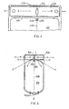
- FIG. 4 an alternative form of extension is shown in which the break is in the form of an elliptical hole 434 in the centre of the extension flap 424.
- the elliptical hole 434 does not break the bottom of weld 426.
- the base of the bag contracts causing a tendency for the notch 434 to open wider causing the extension 424 to form a "fishtail-like" extension at the bottom of the bag.
- the elliptical hole 434 which does not extend through the weld 426 prevents the "fishtailing" of the bag extension 424.
- a weakened tear-line is provided in the bag which is preferably 24 pm in a bag thickness of 0.5 mm.
- a reinforcement 438, 440 preferably in the form of a weld is provided. The weld preferably extends only a distance sufficient to direct any tearing forces along the length of the line of weakness.
- the line of weakness in any of the embodiments may be applied by scoring or by high frequency current in a similar manner to the welding.
- FIG. 5 Another embodiment is shown in Fig. 5.
- a plasma transfer bag 510 has inlet tubes 520 sealed to the bag.
- the extension flap 524 is divided from the main portion of the bag 510 along the line GH.
- An elliptical hole 534 is provided in the extension to form the break in the extension flap when a transverse pull is applied in the direction of the arrows. This causes the bag to split along the line JD along a weakened tear line 536 (as previously described in relation to other embodiments) provided in the bag.
- Reinforcing welds 538, 540 are provided either side of the weakened tear line.
- the part of the bag adjacent the extension flap 524 is rounded such that the curve is a tangent of lines CJ and FJ which intersect the division line GH between the bag and the extension at points K and L erspectively. It is preferred that the angles GKC and HLF be less than 45° and probably in the region of 20° to 30°.
- the curved base has been described in relation to Fig. 5, the bags shown in Figs. 2 and 3 may also have the same dimensions.
- the point J in Fig. 5 should preferably fall in the middle of the elliptical hole 534.
- the two gripping points on the extension flag 524 marked X should preferably be towards the middle line MN of the extension flap 524.
- the middle line MN should not be as close to the line GH as the point J. This prevents the bag from shearing along the lines CJ and FJ rather than along the weakened line DJ.
- the bag 10 of Fig. 1 which is a flat bag is filled with plasma via the inlet tube 20 which is subsequently sealed.
- the bag 10 is then frozen.
- the extension flap 24 is gripped at the two points marked "X" and lateral pull is applied in the directions of the two arrows either side of the notch 34.
- the line of weakness at 36 extending from the notch 34 up the bag on the lateral pull causes the bag 10 to split open, as shown in Fig. 3, and the frozen plasma tablet is ejected.
- the reinforcing means either side of the line of weakness causes the tearing forces to be directed along the line of weakness. Similar use considerations apply with the form of extension flap 424 shown in Fig. 4.
- the line of weakness 436 extends from the ellipitical hole 434 to the inlet tubing but also from the elliptical hole 434 to the bottom weld 426 via weakened line 437. Clamping the bag at the points "X" and providing lateral pull in the direction of arrows causes the line of weakness to break the bag and split it up to the inlet tube along weakened lines 436, 437. The frozen tablet of plasma is ejected without touching the outer surface of the bag 410.
- the bags as described are intended to be used in conjunction with prior art bag stripping machines.
- the bag stripping machine is designed to accept packs between 130 and 160 mm in width and from 200 to 240 mm long. This range has been chosen to allow the pack design for varying volumes of plasma to form frozen tablets of 20 to 30 mm thick.
- the plasma is generally frozen in a mould to form a slab of uniform shape.
- the extension flap is preferably not less than 25 mm deep, i.e. the length being the distance between the lower weld 26 of the extension flap and the lower weld 16 of the bag as shown in Fig. 1 or the corresponding welds 426 and 416 of Fig. 4.
- the holes made for suspending the bag to use the plasma in clinical infusion are generally in the size range of 7 to 10 mm diameter. It is recommended that these holes should be not less than 40 mm from the break in the extension flap and that the point of gripping the bag should be about 37 mm or greater.
- the preferred gripping position is in the centre of the extension flap.
Landscapes
- Health & Medical Sciences (AREA)
- Hematology (AREA)
- Pharmacology & Pharmacy (AREA)
- Life Sciences & Earth Sciences (AREA)
- Animal Behavior & Ethology (AREA)
- General Health & Medical Sciences (AREA)
- Public Health (AREA)
- Veterinary Medicine (AREA)
- Medical Preparation Storing Or Oral Administration Devices (AREA)
- Medicinal Preparation (AREA)
- Bag Frames (AREA)
- Physical Or Chemical Processes And Apparatus (AREA)
- Organic Low-Molecular-Weight Compounds And Preparation Thereof (AREA)
- Apparatus For Disinfection Or Sterilisation (AREA)
- Control And Other Processes For Unpacking Of Materials (AREA)
- External Artificial Organs (AREA)
Claims (8)
Priority Applications (1)
| Application Number | Priority Date | Filing Date | Title |
|---|---|---|---|
| AT85108139T ATE50490T1 (de) | 1984-07-13 | 1985-07-01 | Plasmabeutel. |
Applications Claiming Priority (2)
| Application Number | Priority Date | Filing Date | Title |
|---|---|---|---|
| GB8417914A GB2161453B (en) | 1984-07-13 | 1984-07-13 | Plasma bags |
| GB8417914 | 1984-07-13 |
Publications (3)
| Publication Number | Publication Date |
|---|---|
| EP0167955A2 EP0167955A2 (de) | 1986-01-15 |
| EP0167955A3 EP0167955A3 (en) | 1987-06-16 |
| EP0167955B1 true EP0167955B1 (de) | 1990-02-28 |
Family
ID=10563857
Family Applications (1)
| Application Number | Title | Priority Date | Filing Date |
|---|---|---|---|
| EP85108139A Expired - Lifetime EP0167955B1 (de) | 1984-07-13 | 1985-07-01 | Plasmabeutel |
Country Status (8)
| Country | Link |
|---|---|
| US (1) | US4619650A (de) |
| EP (1) | EP0167955B1 (de) |
| AT (1) | ATE50490T1 (de) |
| DE (1) | DE3576116D1 (de) |
| DK (1) | DK161563C (de) |
| ES (1) | ES287977Y (de) |
| GB (1) | GB2161453B (de) |
| IE (1) | IE56709B1 (de) |
Families Citing this family (25)
| Publication number | Priority date | Publication date | Assignee | Title |
|---|---|---|---|---|
| DE3686764T2 (de) * | 1985-06-14 | 1993-02-11 | Shinsozai Sogo Kenkyusho Kk | Medizinischer fluessigkeitsbehaelter und dessen herstellung. |
| US5215381A (en) * | 1990-04-17 | 1993-06-01 | Wade Steven E | Opening device for flexible packaging |
| US5127065A (en) * | 1990-04-17 | 1992-06-30 | Wade Steven E | Opening device for flexible packaging |
| US5378066A (en) * | 1990-04-17 | 1995-01-03 | Greenbrier Innovations, Inc. | Opening device for flexible packaging |
| US5257983A (en) * | 1991-04-12 | 1993-11-02 | Cryopharm Corporation | Blood bag for lyophilization |
| CA2130893A1 (en) * | 1993-09-17 | 1995-03-18 | Bayer Corporation | Method and system for collecting, processing and storing blood components |
| US5514106A (en) * | 1994-12-20 | 1996-05-07 | Baxter International Inc. | Bag including an identification system indicative of treatment of the bag |
| USD388168S (en) * | 1996-05-13 | 1997-12-23 | Mcgaw, Inc. | Flexible multiple compartment medical container |
| US5910138A (en) * | 1996-05-13 | 1999-06-08 | B. Braun Medical, Inc. | Flexible medical container with selectively enlargeable compartments and method for making same |
| US5944709A (en) | 1996-05-13 | 1999-08-31 | B. Braun Medical, Inc. | Flexible, multiple-compartment drug container and method of making and using same |
| US5928213A (en) * | 1996-05-13 | 1999-07-27 | B. Braun Medical, Inc. | Flexible multiple compartment medical container with preferentially rupturable seals |
| US5876396A (en) * | 1996-09-27 | 1999-03-02 | Baxter International Inc. | System method and container for holding and delivering a solution |
| USD407816S (en) | 1997-05-15 | 1999-04-06 | B. Braun Medical, Inc. | Flexible, multiple-compartment medical container |
| USD402366S (en) | 1997-05-19 | 1998-12-08 | B. Braun Medical, Inc. | Flexible, multiple compartment medical container |
| USD400245S (en) | 1997-06-23 | 1998-10-27 | Bracco Diagnostics Inc. | Flexible medical fluid container |
| USD400253S (en) | 1997-06-23 | 1998-10-27 | Bracco Diagnostics Inc. | Flexible medical fluid container |
| US6361642B1 (en) * | 1997-12-02 | 2002-03-26 | Baxter International Inc. | Heat and pressure-formed flexible containers |
| US6789945B2 (en) * | 2002-08-02 | 2004-09-14 | Hassia Verpackungsmaschinen Gmbh | Sealed three-sided pouch with two chambers |
| US8449520B2 (en) * | 2007-03-19 | 2013-05-28 | HemCon Medical Technologies Inc. | Apparatus and methods for making, storing, and administering freeze-dried materials such as freeze-dried plasma |
| US7776022B2 (en) * | 2007-03-19 | 2010-08-17 | Hemcon Medical Technologies | Apparatus and methods for making, storing, and administering freeze-dried materials such as freeze-dried plasma |
| US7866537B1 (en) * | 2007-06-27 | 2011-01-11 | Duhon David T | Easy-open wrapper |
| KR101479367B1 (ko) * | 2007-07-19 | 2015-01-05 | 가부시키가이샤 오츠까 세이야꾸 고죠 | 멀티-챔버 백 |
| US20170021973A1 (en) * | 2008-05-28 | 2017-01-26 | MaBelle Bray | Multi-Compartment Resealable Storage Bag And Container |
| WO2019099845A1 (en) * | 2017-11-17 | 2019-05-23 | Hollister Incorporated | Receptacles having tear-controlling features |
| US12252301B2 (en) | 2023-02-28 | 2025-03-18 | Inteplast Group Corporation | Multicompartment bag |
Citations (1)
| Publication number | Priority date | Publication date | Assignee | Title |
|---|---|---|---|---|
| EP0076062A2 (de) * | 1981-09-25 | 1983-04-06 | HAEMONETICS CORPORATION(a Massachusetts Corporation) | Behälter zur Speicherung von Blutkomponenten |
Family Cites Families (8)
| Publication number | Priority date | Publication date | Assignee | Title |
|---|---|---|---|---|
| US3257072A (en) * | 1963-01-07 | 1966-06-21 | Cryogenic Eng Co | Whole blood storage structure |
| US3368740A (en) * | 1967-01-17 | 1968-02-13 | Tower Packaging Company | Sheet material with film tear line |
| US3615711A (en) * | 1969-01-27 | 1971-10-26 | Nat Biscuit Co | Package for storing and heating food and method of forming same |
| US3692493A (en) * | 1970-09-22 | 1972-09-19 | Us Health Education & Welfare | Lymphocyte transport bag |
| JPS51103572A (de) * | 1975-03-08 | 1976-09-13 | Kinichi Kimura | |
| US4278198A (en) * | 1977-11-17 | 1981-07-14 | Baxter Travenol Laboratories, Inc. | Flexible collapsible container with a stiffening member |
| US4174040A (en) * | 1977-12-02 | 1979-11-13 | Wang Su Yen | Multi-functional suppository encapsulator |
| EP0159792A3 (de) * | 1984-03-16 | 1986-11-20 | Tuta Laboratories (Australia) Pty Ltd. | Beutelreissmaschine |
-
1984
- 1984-07-13 GB GB8417914A patent/GB2161453B/en not_active Expired
-
1985
- 1985-04-09 US US06/721,637 patent/US4619650A/en not_active Expired - Lifetime
- 1985-07-01 EP EP85108139A patent/EP0167955B1/de not_active Expired - Lifetime
- 1985-07-01 AT AT85108139T patent/ATE50490T1/de active
- 1985-07-01 DE DE8585108139T patent/DE3576116D1/de not_active Expired - Fee Related
- 1985-07-09 ES ES1985287977U patent/ES287977Y/es not_active Expired
- 1985-07-12 IE IE1754/85A patent/IE56709B1/en not_active IP Right Cessation
- 1985-07-12 DK DK320785A patent/DK161563C/da not_active IP Right Cessation
Patent Citations (1)
| Publication number | Priority date | Publication date | Assignee | Title |
|---|---|---|---|---|
| EP0076062A2 (de) * | 1981-09-25 | 1983-04-06 | HAEMONETICS CORPORATION(a Massachusetts Corporation) | Behälter zur Speicherung von Blutkomponenten |
Also Published As
| Publication number | Publication date |
|---|---|
| IE56709B1 (en) | 1991-11-06 |
| US4619650A (en) | 1986-10-28 |
| DK161563C (da) | 1992-01-06 |
| DK320785A (da) | 1986-01-14 |
| ES287977Y (es) | 1987-01-16 |
| GB2161453B (en) | 1989-05-17 |
| IE851754L (en) | 1986-01-13 |
| ATE50490T1 (de) | 1990-03-15 |
| DK161563B (da) | 1991-07-22 |
| DE3576116D1 (de) | 1990-04-05 |
| EP0167955A2 (de) | 1986-01-15 |
| GB8417914D0 (en) | 1984-08-15 |
| GB2161453A (en) | 1986-01-15 |
| DK320785D0 (da) | 1985-07-12 |
| EP0167955A3 (en) | 1987-06-16 |
| ES287977U (es) | 1986-05-16 |
Similar Documents
| Publication | Publication Date | Title |
|---|---|---|
| US4619650A (en) | Plasma bags | |
| KR100212640B1 (ko) | 즉석 사용가능한 동물 정액 포장팩 제조 장치 및 그에 따라 제조되는 동물 정액 포장팩 | |
| US4480751A (en) | Apparatus for collecting, storing and dispensing frozen blood plasma | |
| KR101913763B1 (ko) | 혈액 제품 백을 비우기 위한 장치 | |
| SK53497A3 (en) | Method of aseptic and automatic transfer of pharmaceutical containers and device for carrying out this method aseptic transfer | |
| CA2130893A1 (en) | Method and system for collecting, processing and storing blood components | |
| AU715207B2 (en) | Transfer system between a bag and a sterile enclosure | |
| CA2318624A1 (en) | Method and apparatus for aseptically packaging and dispensing live material | |
| AU586922B2 (en) | A method and an arrangement for the finishing of an opening arrangement on a packing container | |
| EP0796792B1 (de) | Verfahren zum sterilen Verpacken eines Produktes | |
| US11066631B2 (en) | Pack | |
| EP3294254A1 (de) | Kryogener aufbewahrungsbeutel | |
| NL8000829A (nl) | Wegbreekdeksel. | |
| EP2857492B1 (de) | Paket für zellenhaltige materialien und paket mit zellenhaltigen materialien | |
| GB2133383A (en) | Plasma bags | |
| KR930010159B1 (ko) | 가융성 재료위한 용기 | |
| KR19990036008A (ko) | 개별적인 일관 최종 포장 공정을 갖춘 용액 분배 시스템 및 그 포장 방법 | |
| KR20050099988A (ko) | 단일 부재 이중 챔버 용기 | |
| US20080296198A1 (en) | Capped Ampoule to Be Filled With A Liquid By Vacuum and Corresponding Production Method | |
| JPH02252459A (ja) | 引き裂き開封可能な血液バッグ | |
| CN215350692U (zh) | 一种免清洗、适于电磁抓取或释放的血浆袋 | |
| JPH0347260A (ja) | 引き裂き開封可能な血液バッグ | |
| JP4517918B2 (ja) | ピペット包装体 | |
| CA2238056C (en) | Transfer system between a bag and a sterile enclosure | |
| WO1990011934A3 (de) | Verfahren zur herstellung von in streifen verpackten portionen speiseeis, hiermit gefüllte verpackungen, sowie vorrichtung zu deren ausgabe |
Legal Events
| Date | Code | Title | Description |
|---|---|---|---|
| PUAI | Public reference made under article 153(3) epc to a published international application that has entered the european phase |
Free format text: ORIGINAL CODE: 0009012 |
|
| 17P | Request for examination filed |
Effective date: 19850701 |
|
| AK | Designated contracting states |
Designated state(s): AT BE CH DE FR IT LI LU NL SE |
|
| PUAL | Search report despatched |
Free format text: ORIGINAL CODE: 0009013 |
|
| AK | Designated contracting states |
Kind code of ref document: A3 Designated state(s): AT BE CH DE FR IT LI LU NL SE |
|
| RAP1 | Party data changed (applicant data changed or rights of an application transferred) |
Owner name: MILES INC. |
|
| 17Q | First examination report despatched |
Effective date: 19890418 |
|
| GRAA | (expected) grant |
Free format text: ORIGINAL CODE: 0009210 |
|
| AK | Designated contracting states |
Kind code of ref document: B1 Designated state(s): AT BE CH DE FR IT LI LU NL SE |
|
| REF | Corresponds to: |
Ref document number: 50490 Country of ref document: AT Date of ref document: 19900315 Kind code of ref document: T |
|
| ET | Fr: translation filed | ||
| REF | Corresponds to: |
Ref document number: 3576116 Country of ref document: DE Date of ref document: 19900405 |
|
| ITF | It: translation for a ep patent filed | ||
| PLBE | No opposition filed within time limit |
Free format text: ORIGINAL CODE: 0009261 |
|
| STAA | Information on the status of an ep patent application or granted ep patent |
Free format text: STATUS: NO OPPOSITION FILED WITHIN TIME LIMIT |
|
| 26N | No opposition filed | ||
| EPTA | Lu: last paid annual fee | ||
| ITTA | It: last paid annual fee | ||
| EAL | Se: european patent in force in sweden |
Ref document number: 85108139.8 |
|
| PGFP | Annual fee paid to national office [announced via postgrant information from national office to epo] |
Ref country code: LU Payment date: 19950601 Year of fee payment: 11 |
|
| PG25 | Lapsed in a contracting state [announced via postgrant information from national office to epo] |
Ref country code: LU Free format text: LAPSE BECAUSE OF NON-PAYMENT OF DUE FEES Effective date: 19960701 |
|
| PGFP | Annual fee paid to national office [announced via postgrant information from national office to epo] |
Ref country code: SE Payment date: 19960717 Year of fee payment: 12 |
|
| REG | Reference to a national code |
Ref country code: CH Ref legal event code: PUE Owner name: MILES INC. TRANSFER- BAYER CORPORATION * BAYER COR |
|
| NLS | Nl: assignments of ep-patents |
Owner name: PALL CORPORATION |
|
| NLT1 | Nl: modifications of names registered in virtue of documents presented to the patent office pursuant to art. 16 a, paragraph 1 |
Owner name: BAYER CORPORATION |
|
| BECA | Be: change of holder's address |
Free format text: 960918 *PALL CORP.:25 HARBOR PARK DRIVE PORT WASHINGTON NY 11050 |
|
| BECH | Be: change of holder |
Free format text: 960918 *PALL CORP.:25 HARBOR PARK DRIVE PORT WASHINGTON NY 11050 |
|
| PGFP | Annual fee paid to national office [announced via postgrant information from national office to epo] |
Ref country code: CH Payment date: 19970630 Year of fee payment: 13 |
|
| PG25 | Lapsed in a contracting state [announced via postgrant information from national office to epo] |
Ref country code: SE Effective date: 19970702 |
|
| PGFP | Annual fee paid to national office [announced via postgrant information from national office to epo] |
Ref country code: BE Payment date: 19970812 Year of fee payment: 13 |
|
| EUG | Se: european patent has lapsed |
Ref document number: 85108139.8 |
|
| PG25 | Lapsed in a contracting state [announced via postgrant information from national office to epo] |
Ref country code: LI Free format text: LAPSE BECAUSE OF NON-PAYMENT OF DUE FEES Effective date: 19980731 Ref country code: CH Free format text: LAPSE BECAUSE OF NON-PAYMENT OF DUE FEES Effective date: 19980731 Ref country code: BE Free format text: LAPSE BECAUSE OF NON-PAYMENT OF DUE FEES Effective date: 19980731 |
|
| REG | Reference to a national code |
Ref country code: FR Ref legal event code: TP Ref country code: FR Ref legal event code: CD |
|
| BERE | Be: lapsed |
Owner name: PALL CORP. Effective date: 19980731 |
|
| REG | Reference to a national code |
Ref country code: CH Ref legal event code: PL |
|
| PGFP | Annual fee paid to national office [announced via postgrant information from national office to epo] |
Ref country code: DE Payment date: 19990706 Year of fee payment: 15 |
|
| PGFP | Annual fee paid to national office [announced via postgrant information from national office to epo] |
Ref country code: FR Payment date: 19990709 Year of fee payment: 15 |
|
| PGFP | Annual fee paid to national office [announced via postgrant information from national office to epo] |
Ref country code: AT Payment date: 19990713 Year of fee payment: 15 |
|
| PGFP | Annual fee paid to national office [announced via postgrant information from national office to epo] |
Ref country code: NL Payment date: 19990730 Year of fee payment: 15 |
|
| PG25 | Lapsed in a contracting state [announced via postgrant information from national office to epo] |
Ref country code: AT Free format text: LAPSE BECAUSE OF NON-PAYMENT OF DUE FEES Effective date: 20000701 |
|
| PG25 | Lapsed in a contracting state [announced via postgrant information from national office to epo] |
Ref country code: NL Free format text: LAPSE BECAUSE OF NON-PAYMENT OF DUE FEES Effective date: 20010201 |
|
| PG25 | Lapsed in a contracting state [announced via postgrant information from national office to epo] |
Ref country code: FR Free format text: LAPSE BECAUSE OF NON-PAYMENT OF DUE FEES Effective date: 20010330 |
|
| NLV4 | Nl: lapsed or anulled due to non-payment of the annual fee |
Effective date: 20010201 |
|
| REG | Reference to a national code |
Ref country code: FR Ref legal event code: ST |
|
| PG25 | Lapsed in a contracting state [announced via postgrant information from national office to epo] |
Ref country code: DE Free format text: LAPSE BECAUSE OF NON-PAYMENT OF DUE FEES Effective date: 20010501 |