EP0169036A2 - Système et méthode pour l'installation de distribution électrique à grande puissance - Google Patents
Système et méthode pour l'installation de distribution électrique à grande puissance Download PDFInfo
- Publication number
- EP0169036A2 EP0169036A2 EP85304997A EP85304997A EP0169036A2 EP 0169036 A2 EP0169036 A2 EP 0169036A2 EP 85304997 A EP85304997 A EP 85304997A EP 85304997 A EP85304997 A EP 85304997A EP 0169036 A2 EP0169036 A2 EP 0169036A2
- Authority
- EP
- European Patent Office
- Prior art keywords
- cable
- conductor
- conductors
- phase
- power outlet
- Prior art date
- Legal status (The legal status is an assumption and is not a legal conclusion. Google has not performed a legal analysis and makes no representation as to the accuracy of the status listed.)
- Withdrawn
Links
- 238000009434 installation Methods 0.000 title claims description 11
- 238000000034 method Methods 0.000 title claims description 9
- 239000004020 conductor Substances 0.000 claims abstract description 147
- 230000007935 neutral effect Effects 0.000 claims description 28
- 239000000758 substrate Substances 0.000 claims description 4
- NJPPVKZQTLUDBO-UHFFFAOYSA-N novaluron Chemical compound C1=C(Cl)C(OC(F)(F)C(OC(F)(F)F)F)=CC=C1NC(=O)NC(=O)C1=C(F)C=CC=C1F NJPPVKZQTLUDBO-UHFFFAOYSA-N 0.000 description 21
- 230000007704 transition Effects 0.000 description 8
- 230000000694 effects Effects 0.000 description 4
- 230000006872 improvement Effects 0.000 description 2
- 238000009413 insulation Methods 0.000 description 2
- 239000012212 insulator Substances 0.000 description 2
- 238000010079 rubber tapping Methods 0.000 description 2
- 230000008901 benefit Effects 0.000 description 1
- 239000003086 colorant Substances 0.000 description 1
- 238000002788 crimping Methods 0.000 description 1
- 238000010586 diagram Methods 0.000 description 1
- 238000006073 displacement reaction Methods 0.000 description 1
- 238000010292 electrical insulation Methods 0.000 description 1
- 230000007717 exclusion Effects 0.000 description 1
- 238000007373 indentation Methods 0.000 description 1
- CNQCVBJFEGMYDW-UHFFFAOYSA-N lawrencium atom Chemical compound [Lr] CNQCVBJFEGMYDW-UHFFFAOYSA-N 0.000 description 1
- 239000000463 material Substances 0.000 description 1
- 239000002184 metal Substances 0.000 description 1
- 230000010287 polarization Effects 0.000 description 1
- 230000001681 protective effect Effects 0.000 description 1
- 230000009467 reduction Effects 0.000 description 1
- 230000008439 repair process Effects 0.000 description 1
Images



Classifications
-
- H—ELECTRICITY
- H01—ELECTRIC ELEMENTS
- H01R—ELECTRICALLY-CONDUCTIVE CONNECTIONS; STRUCTURAL ASSOCIATIONS OF A PLURALITY OF MUTUALLY-INSULATED ELECTRICAL CONNECTING ELEMENTS; COUPLING DEVICES; CURRENT COLLECTORS
- H01R12/00—Structural associations of a plurality of mutually-insulated electrical connecting elements, specially adapted for printed circuits, e.g. printed circuit boards [PCB], flat or ribbon cables, or like generally planar structures, e.g. terminal strips, terminal blocks; Coupling devices specially adapted for printed circuits, flat or ribbon cables, or like generally planar structures; Terminals specially adapted for contact with, or insertion into, printed circuits, flat or ribbon cables, or like generally planar structures
- H01R12/50—Fixed connections
- H01R12/59—Fixed connections for flexible printed circuits, flat or ribbon cables or like structures
-
- H—ELECTRICITY
- H01—ELECTRIC ELEMENTS
- H01R—ELECTRICALLY-CONDUCTIVE CONNECTIONS; STRUCTURAL ASSOCIATIONS OF A PLURALITY OF MUTUALLY-INSULATED ELECTRICAL CONNECTING ELEMENTS; COUPLING DEVICES; CURRENT COLLECTORS
- H01R12/00—Structural associations of a plurality of mutually-insulated electrical connecting elements, specially adapted for printed circuits, e.g. printed circuit boards [PCB], flat or ribbon cables, or like generally planar structures, e.g. terminal strips, terminal blocks; Coupling devices specially adapted for printed circuits, flat or ribbon cables, or like generally planar structures; Terminals specially adapted for contact with, or insertion into, printed circuits, flat or ribbon cables, or like generally planar structures
- H01R12/50—Fixed connections
- H01R12/59—Fixed connections for flexible printed circuits, flat or ribbon cables or like structures
- H01R12/61—Fixed connections for flexible printed circuits, flat or ribbon cables or like structures connecting to flexible printed circuits, flat or ribbon cables or like structures
- H01R12/613—Fixed connections for flexible printed circuits, flat or ribbon cables or like structures connecting to flexible printed circuits, flat or ribbon cables or like structures by means of interconnecting elements
- H01R12/616—Fixed connections for flexible printed circuits, flat or ribbon cables or like structures connecting to flexible printed circuits, flat or ribbon cables or like structures by means of interconnecting elements having contacts penetrating insulation for making contact with conductors, e.g. needle points
-
- H—ELECTRICITY
- H01—ELECTRIC ELEMENTS
- H01R—ELECTRICALLY-CONDUCTIVE CONNECTIONS; STRUCTURAL ASSOCIATIONS OF A PLURALITY OF MUTUALLY-INSULATED ELECTRICAL CONNECTING ELEMENTS; COUPLING DEVICES; CURRENT COLLECTORS
- H01R12/00—Structural associations of a plurality of mutually-insulated electrical connecting elements, specially adapted for printed circuits, e.g. printed circuit boards [PCB], flat or ribbon cables, or like generally planar structures, e.g. terminal strips, terminal blocks; Coupling devices specially adapted for printed circuits, flat or ribbon cables, or like generally planar structures; Terminals specially adapted for contact with, or insertion into, printed circuits, flat or ribbon cables, or like generally planar structures
- H01R12/70—Coupling devices
- H01R12/77—Coupling devices for flexible printed circuits, flat or ribbon cables or like structures
Definitions
- This invention relates generally to distibution of electrical power and pertains more particularly to multi- conductor flat cable power distribution and methods for installing systems therewith.
- One of the initially introduced commercial undercarpet wiring systems involves a method of laying one cable upon another and interconnecting conductors by forming an opening through the conductors, placing a generally L-shaped insulation-piercing connector in the opening and crimping same upon exterior surfaces of the cables to provide interconnection without the connector straddling or otherwise extending over any conductors other than those intended to be interconnected.
- both of the above types of systems In conducting power from a first or main cable run connected to the power feeder of a building to a desired power location, both of the above types of systems extend a second cable, connected as described above to the main cable, to such location and there discrerely wire a power outlet pedestal of conventional character to a transition fitting which itself is in insulation-piercing relation with the second cable at such location.
- Pedestals have thus become known which may be applied directly to a single-phase, three-conductor cable, insulation-piercing contacts of such pedestals having inrernal copnnectors having insulation-piercing end portions for electrical connection with the cable conductors and other end portions adapted for engagement with the prongs of plugs inserted in pedestal power outlet receptacles.
- a device of this type is shown in commonly-assigned U. S. Patent No. 4,479,692 issued October 30, 1981, and entitled "Receptacle for Flat Multi-Conductor Cable".
- the known connections directly to five conductor flat cable are not at visibly determinable locations upon completion of system installation and placement of carpeting atop the system.
- the abutting and overlapping connections alluded to at the outset above are not power outlet locations, but are secreted beneath the carpeting in locations only determinable by reference to the installation wiring drawings or, in their absence or departure therefrom, only by removing carpet squares and inspecting the system.
- the present invention has as ics primary object the provision of improved planning and installing of flat conductor cable power distribution systems.
- Another general object of the invention is to provide undercarpet power distribution installations with the practically desirable characteristic of traditional conduit systems above noted.
- a more particular object of the invention is to expand interconnections to five conductor flat cable and thus effect a reduction in required numbers of non-pedestal connections in the installation of such systems.
- the invention provides a method of successively effecting - pedestal connections, directly upon a flat cable main run with multiple live conductors, at respective different phases of such main run.
- all needed service outlet locations can be served by secondary cables of three or four conductors having connection to the main cable run at power outlet locations thereon.
- FIG. 8 an installation area is shown wherein a system planner has elected to distribute power on a per phase basis respectively into different zones I-l, I-2, II and III, for phase-balancing or other purposes.
- one connects power mains or discrete feeder conductors 210, comprising phase conductors 212, 214 and 216, ground conductors 218 and neutral conductor 220 at transition box 222, to flat conductor cable 224.
- Cable 224 has an electrically conductive shield 226 and individual rectangular cross-section phase conductors 228, 230 and 232, ground conductor 234 and neutral conductor 236, all encased in electrically insulative casing 238.
- Perforated margins 240 intervene encased conductors to facilitate tearing or otherwise separating individual insulated conductors from the cable.
- Cable 224 extends in a main run from box 222 to first phase pedestal power outlet 242, the structure of which will be discussed in detail below, whereat secondary cable 244 has its three conductors respectively electrically connected to phase conductor 228, ground conductor 234 and neutral conductor 236 of cable 224.
- Secondary cable 244 extends through outlet connection 242 and is folded upon itself aside same to define secondary cable runs 244a and 244b, which have indicated opposite sense run directions, as shown, perpendicular to cable 224.
- Pedestal power outlets 246 and 248 are applied to cable run 244a and pedestal power outlet 250 to cable run 244b, other outlets being added as desired on runs 244a and 244b, which may be further folded to effect directional changes.
- Outlets 246, 248 and 250 may be of type shown in the above-referenced '661 application.
- Main cable 224 continues beyond pedestal connection 242 and cable run 244b into second phase pedestal power outlet 252 at which another secondary cable 254 has its three conductors respectively, electrically connected to phase conductor 230, ground conductor 234 and neutral conductor 236 of cable 224.
- Secondary cable 254 extends through connection outlet 252 and is folded upon itself aside same to define cable runs 254a and 254b, which have indicated like sense run directions, as shown, perpendicular to cable 224.
- Pedestal power outlets 255 and 253, oE like type to units 246, 248 and 250, are applied respectively co cable runs 234a and 254b.
- Main cable 224 further continues beyond pedestal connection 252 and cable run 254b into third phase pedestal power outlet 260, which may be the final termination for cable 224.
- further secondary cable 262 has its three conductors respectively connected to phase conductor 232 of cable 224 and has its ground and neutral conductors connected to those of cable 224.
- Cable 262 extends to one side of outlet connection 260 and is folded at such side to define secondary cable run 262a, to which pedestal power outlet 264, again of type shown in the application noted above, is connected.
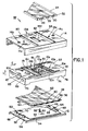
- FIG. 1 a connecting device for use as units 242, 252 and 260 and thus enabling the system and practice of Fig. 8 is shown, including contact support member 10, base 12 and cover 14.
- Support member 10 is formed of a suitable insulative material and is generally of rectangular configuration, being elongate in direction E and upstanding in direction U.
- a first contact element set comprising contact elements 16, 18 and 20 is disposed in fixed positional manner on first surface 22 of support member 10, for confronting a three conductor cable 24.
- Cable 24 includes flat conductors 26, 28 and 30 disposed in insulative casing 32.
- conductor 30 is an electrical neutral conductor and casing 32 includes a white coloration to identify this conductor.
- Conductor 28 is the ground conductor and casing 32 includes a green coloration overlying same.
- Conductor 26 is a live (single-phase) conductor and may bear overlying casing indication in the colors black, red or blue.
- Contact elements 16, 18 and 20 are of insulation-piercing type and will respectively engage electrically conductors 26, 28 and 30 upon assembly.
- a second contact element set is included in support member 10, to be discussed more particularly below in connection with Fig. 2, and is disposed at the underside of support member 10 for engagement with conductors of a cable 34.
- Cable 34 is shown to be of five conductor (three-phase) type having neutral conductor 36, ground conductor 38 and individual phase conductors 40, 42 and 44 (A, B and C phases). The conductors of cable 34 are also typically color-coded.
- Base 12 includes cable guides 46-52 aside cable receipt expanse 52 which is defined by an insulative layer 34 disposed atoo metal substrate 55.
- Securing means 53 is preferably integral with substrate 56 and is in the form of a threaded member having an annular insulator 60 adjacent insulative layer 54.
- the positioning of threaded means 58 in relation to guides 46-52 is such that, upon placement of cable 34 upon base 12, means 58 passes through cable 34 at location 62, i.e., through the insulation between conductors 38 and 40, at which time annular insulator 60 is resident in cable 34, precluding electrical continuity, through means 58, between conductors 38 and 40.
- support member 10 includes a central lower indentation 74 through which cable 34 will extend upon assembly. Legs 76 and 78 of member 10 will abut the upper surface of base 12 on assembly.
- Cover 14 is dimensioned to fit telescopically over support member 10 on assembly and includes upper surface openings 80, 82 and 84, through which contacts 16, 18 and 20 respectively extend to engage cable 24 when the latter is applied to the upper surface of cover 14.
- openings 14a and 10a are aligned, as are openings 14b and 10b to permit threading of screws into posts 64 and 66.
- a nut is applied in opening 10c to securing means 58.
- upper surface 22 includes contact seats 86, 88 and 90, the perimeters of which extend upwardly from surface 22 in measure equal to the depth of cover 14 adjacent openings 80-84 of Fig. 1.
- Elongate channels 92 and 94 extend in both directions from contact seat 86.
- Channels 96 and 98 extend rightwardly of contact seat 88 and into contact seat 90.
- Channels 100 and 102 extend rightwardly of contact seat 90.
- Contact element 16 has flanges 104 and 106 integral therewith and serving as conductive means for electrically connection contact element 16 with its counterpart contact element 108 of the second set of contacts referred to above. As will be discussed further below, contact element 108 is supported in flanges 104 and 106 for translatory movement in support member 10.
- Contact element 18 includes flanges 110 and 112, again integral therewith, and serving as conductive means for interconnecting contact element 18 with its counterpart contact element 114 of the second set.
- Contact element .20 has integral flanges 116 and 118 serving as conductive means for connecting same with its counterpart contact element 120 of the second set.
- Contact element 16 includes in flange 104 a track 104a to support contact element 108 for translation into any selective one of three positions.
- flange 106 includes detents in the form of through openings 106a, 106b, and 106c.
- Contact 108 includes end flanges 108a and 108b, which are respectively exteriorly aside flanges 104 and 106 upon assembly of contact elements 16 and 108.
- Wall 108c is struck upwardly from the floor of contact element 108 to provide a channel 108d, in which flange 104 resides.
- a threaded member 107 passes through opening 108e, through track 104a and is threaded into opening 108f to secure the assembly.
- Boss 108g is situated on the interior side of flange 108b and is sized to removably reside in any of openings 106a, 106b or 105c to effect the proper positioning of contact element 103.
- FIG. 2 An assembly of a first set contact element and a second set contact element is shown in Fig. 2 in the case of contact element 18 and its counterpart second set contact element 114 in Fig. 2 with parts being identified in a manner similar to those designated for contact elements 16 and 108.
- the first set contact elements are first inserted as follows.
- Flanges 104 and 106 are disposed in channels 92 and 94, whereby contact element 16 resides on seat 86.
- Flanges 110 and 112 are disposed in channels 96 and 98, whereby contact element 18 resides on - seat 88.
- Flanges 116 and 118 are disposed in channels 100 and 102, whereby contact element 20 resides on seat 90, being spaced by member 10 above flanges 110 and 112, which are stepped down as indicated.
- contact elements 114 and 120 are inserted into the underside of member 10 and secured respectively to flanges 110, 112 and 116, 118. Selection is made for the state of contact element 108 and it is inserted into the underside of member 10, translated into selected position and secured in place. The showing of member 10 in Fig. 1 is thus reached.
- the assembly of components above discussed is expanded to include receptacle 122 and the respective and fascener screws 124, 123 and a grounding fastener screw 126.
- the receptacle 122 carries indicia as at 130 which are cooperative with the indicia on the cable indicative of proper receptacle orientation to insure correct polarity of electrical connections to be made. Further in this regard and to insure proper placement orientation of the receptacle on the cable, the receptacle has screw-through passages which function as a telltale cooperative with cover openings 14c-e and support member openings 10d-f (Fig. 1) when correct receptacle placement is effected to indicate such condition.
- tabs 136, 138 at the underside of the receptacle which must pass through cable 24 at perforations between the ground conductor and the live and neutral conductors and be received in openings 134, 135 of cover 14 and support member 10, respectively, in order for the receptacle to seat properly. If reciprocal orientation were attempted, the tabs would not line up with openings 134, 135 and hence not pass therethrough preventing proper seating.
- the protective metallic or grounding shield 140 on top of cable 24 will, as a preliminary to connecting the receptacle thereto, be removed or cut and laid back in the rectangular pattern as shown in regions overlying the live and neutral conductors 26 and 30 of the cable leaving exposed the insulative covering in which said conductors are encased.
- the shield may be cut and laid back by folding same rightwardly on top of uncut portions of the shield since this facilitates effecting repair to the shield in the event the receptacle is removed.
- cable preparation is made for cable 34 of Fig. 1. It should be appreciated, however, that the cable may be prepared by full displacement of the cable shield so as to expose the entire upper surface thereof for insulation-piercing connection to the receptacle.
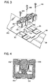
- Figs. 2-5 of such application show the contact elements thereof as having first end portions for engaging the appliance prong terminals and second end portions for insulation piercing the cable.
- Fig. 4 hereof shows a typical section of the pedestal with appliance prongs shown at 142, 144, with contact element first portions at 146, 148 and with second end portions 150, 154.
- contact support member 10 is shown schematically in first operative state between cables 24 and 34, as it would be upon securement of the Fig. 3 to the Fig 1 connection device with the cables in indicated position.
- cable 24 is laterally centered with respect to support member 10, as is also the case for cable 34.
- neutral conductor 30 laterally overlies ground conductor 38, the support member effects a lateral connection transition of one conductor step, whereby conductor 30 is connectable to its counterpart neutral conductor 36, flanges 116 and 118 effecting such transition between first set contact element 20 and second set contact element 120.
- a like one step transition is also fixedly provided as between ground conductors 28 and 38 through flanges 110 and 112 interconnecting first set contact element 18 and second set counterpart element 114.
- a further one step transition rightwardly is also provided as between phase conductors 26 and 40 through flanges 104 and 106.
- contact support member 10 is shown schematically in second operative state. As will be seen, cable 24 is again laterally centered with respect to support member 10, as is cable 34.
- contact support member 10 is shown schematically in third operative state.
- Cable 24 is again laterally centered with respect to support member 10, as is cable 34.
- the one step transitions are present for the neutral and ground conductors, but support member is now set such that contact element 108 is in registration with conductor 44, the third phase conductor of cable 34.
- This setting thus provides for interconnection of conductor 26 of cable 24 with conductor 44, and the associated pedestal is powered by the C phase.
- the invention broadly provides a flat conductor cable power distribution system comprising a discrete wire multi-phase feeder, a main flat cable having at least four conductors and connected to the feeder allowing plural phase energization and an insulation-piercing power outlet receptacle connected to the main cable and energized with a selective one of such phases.
- the system may further include a secondary flat conductor cable connected to the main cable at the power outlet receptacle and energized by such one phase.
- the system is typically multiphase wherein the foregoing practice is repeated for each phase.
- a flat conductor cable power distribution system comprising a discrete wire three-phase feeder, a main flat cable having five conductors and connected to the feeder to have energization in first, second and third phases and first, second and third insulation-piercing power outlet receptacles connected to said main cable at different locations thereon and energized respectively by the first, second and third phases.
- a flat conductor cable power distribution system disposed upon a substrate and covered by an overcover, the system including a main cable energized in plural phases, a plurality of secondary cables connected to the main cable and power outlet receptacles - connected to the main cable and the secondary cables, each such connection of the main and secondary cables being discernible by structure of the receptacles disposed visibly upon the overcover.
Landscapes
- Multi-Conductor Connections (AREA)
- Installation Of Indoor Wiring (AREA)
- Coupling Device And Connection With Printed Circuit (AREA)
Applications Claiming Priority (2)
| Application Number | Priority Date | Filing Date | Title |
|---|---|---|---|
| US63079584A | 1984-07-13 | 1984-07-13 | |
| US630795 | 1984-07-13 |
Publications (2)
| Publication Number | Publication Date |
|---|---|
| EP0169036A2 true EP0169036A2 (fr) | 1986-01-22 |
| EP0169036A3 EP0169036A3 (fr) | 1987-08-05 |
Family
ID=24528594
Family Applications (1)
| Application Number | Title | Priority Date | Filing Date |
|---|---|---|---|
| EP85304997A Withdrawn EP0169036A3 (fr) | 1984-07-13 | 1985-07-12 | Système et méthode pour l'installation de distribution électrique à grande puissance |
Country Status (4)
| Country | Link |
|---|---|
| EP (1) | EP0169036A3 (fr) |
| JP (1) | JP2610813B2 (fr) |
| AU (1) | AU565007B2 (fr) |
| CA (1) | CA1239673A (fr) |
Families Citing this family (1)
| Publication number | Priority date | Publication date | Assignee | Title |
|---|---|---|---|---|
| JPH0710548A (ja) * | 1993-06-18 | 1995-01-13 | Sumitomo Electric Ind Ltd | フッ化物ガラスの製造方法 |
Family Cites Families (4)
| Publication number | Priority date | Publication date | Assignee | Title |
|---|---|---|---|---|
| US4315662A (en) * | 1979-05-25 | 1982-02-16 | Thomas & Betts Corporation | Undercarpet wiring system installation kit |
| US4258974A (en) * | 1979-05-25 | 1981-03-31 | Thomas & Betts Corporation | Installation kit for undercarpet wiring system |
| DE3473697D1 (en) * | 1983-06-06 | 1988-09-29 | Amp Inc | Electrical connector and kit |
| US4602840A (en) * | 1984-06-01 | 1986-07-29 | Harvey Hubbell Incorporated | Under-carpet connection system |
-
1985
- 1985-07-11 AU AU44798/85A patent/AU565007B2/en not_active Ceased
- 1985-07-12 EP EP85304997A patent/EP0169036A3/fr not_active Withdrawn
- 1985-07-12 CA CA000486690A patent/CA1239673A/fr not_active Expired
- 1985-07-13 JP JP60153409A patent/JP2610813B2/ja not_active Expired - Lifetime
Also Published As
| Publication number | Publication date |
|---|---|
| AU4479885A (en) | 1986-01-16 |
| JP2610813B2 (ja) | 1997-05-14 |
| AU565007B2 (en) | 1987-09-03 |
| EP0169036A3 (fr) | 1987-08-05 |
| CA1239673A (fr) | 1988-07-26 |
| JPS6158414A (ja) | 1986-03-25 |
Similar Documents
| Publication | Publication Date | Title |
|---|---|---|
| US10297999B2 (en) | Electrical distribution system | |
| US6870099B1 (en) | Prewired electrical apparatus having quick connect components | |
| US4717357A (en) | System and method for electrical power installation | |
| US3860739A (en) | Method and apparatus for a wiring system utilizing wiring devices | |
| US4627675A (en) | Wiring system with quick connect wire terminals | |
| US4563050A (en) | Device for flat multiconductor cable connection | |
| GB2165086A (en) | Electric cables | |
| US4480889A (en) | Adapter and method for tapping or splicing flat multiconductor cable | |
| JPH05508515A (ja) | モジュール配線システム | |
| JPH0324032B2 (fr) | ||
| US5243129A (en) | Flexible undercarpet power system | |
| US3207839A (en) | Busduct equipment with polarized elements and conduit shell joining means | |
| US6227903B1 (en) | Circuit connector block | |
| EP0169036A2 (fr) | Système et méthode pour l'installation de distribution électrique à grande puissance | |
| US6730844B2 (en) | Dual-purpose wiring device and method of wiring | |
| US20030171039A1 (en) | Electrical box for providing electrical power and low voltage signals to a building | |
| GB2165101A (en) | Electrical connection devices for use with flat cable | |
| CA1235204A (fr) | Dispositif isole de mise a la terre pour cable en nappe sous moquette | |
| JPH08264209A (ja) | 配電用分岐器 | |
| JP2516629Y2 (ja) | アンダーカーペットタップ | |
| JPS6129163Y2 (fr) | ||
| JPH0251307A (ja) | 低圧幹線分岐部の電圧検知装置 | |
| JPH0730514U (ja) | 積算電力計取付け用端子台付き分電盤 | |
| US20060281345A1 (en) | Self-locking junction box | |
| JPS632268A (ja) | カーペット下敷きケーブル用分岐接続キット |
Legal Events
| Date | Code | Title | Description |
|---|---|---|---|
| PUAI | Public reference made under article 153(3) epc to a published international application that has entered the european phase |
Free format text: ORIGINAL CODE: 0009012 |
|
| AK | Designated contracting states |
Designated state(s): BE CH DE FR GB IT LI NL SE |
|
| PUAL | Search report despatched |
Free format text: ORIGINAL CODE: 0009013 |
|
| AK | Designated contracting states |
Kind code of ref document: A3 Designated state(s): BE CH DE FR GB IT LI NL SE |
|
| 17P | Request for examination filed |
Effective date: 19880123 |
|
| 17Q | First examination report despatched |
Effective date: 19891110 |
|
| STAA | Information on the status of an ep patent application or granted ep patent |
Free format text: STATUS: THE APPLICATION IS DEEMED TO BE WITHDRAWN |
|
| 18D | Application deemed to be withdrawn |
Effective date: 19910829 |
|
| RIN1 | Information on inventor provided before grant (corrected) |
Inventor name: GREENWOOD, WILLIAM S. |