EP0169367A1 - Auswechselbares optisches Informationsaufzeichnungsmedium - Google Patents
Auswechselbares optisches Informationsaufzeichnungsmedium Download PDFInfo
- Publication number
- EP0169367A1 EP0169367A1 EP19850107452 EP85107452A EP0169367A1 EP 0169367 A1 EP0169367 A1 EP 0169367A1 EP 19850107452 EP19850107452 EP 19850107452 EP 85107452 A EP85107452 A EP 85107452A EP 0169367 A1 EP0169367 A1 EP 0169367A1
- Authority
- EP
- European Patent Office
- Prior art keywords
- recording medium
- recording
- optical information
- information recording
- erasing
- Prior art date
- Legal status (The legal status is an assumption and is not a legal conclusion. Google has not performed a legal analysis and makes no representation as to the accuracy of the status listed.)
- Granted
Links
Images


Classifications
-
- G—PHYSICS
- G11—INFORMATION STORAGE
- G11B—INFORMATION STORAGE BASED ON RELATIVE MOVEMENT BETWEEN RECORD CARRIER AND TRANSDUCER
- G11B7/00—Recording or reproducing by optical means, e.g. recording using a thermal beam of optical radiation by modifying optical properties or the physical structure, reproducing using an optical beam at lower power by sensing optical properties; Record carriers therefor
- G11B7/24—Record carriers characterised by shape, structure or physical properties, or by the selection of the material
- G11B7/241—Record carriers characterised by shape, structure or physical properties, or by the selection of the material characterised by the selection of the material
- G11B7/242—Record carriers characterised by shape, structure or physical properties, or by the selection of the material characterised by the selection of the material of recording layers
- G11B7/243—Record carriers characterised by shape, structure or physical properties, or by the selection of the material characterised by the selection of the material of recording layers comprising inorganic materials only, e.g. ablative layers
- G11B2007/24302—Metals or metalloids
- G11B2007/24308—Metals or metalloids transition metal elements of group 11 (Cu, Ag, Au)
-
- G—PHYSICS
- G11—INFORMATION STORAGE
- G11B—INFORMATION STORAGE BASED ON RELATIVE MOVEMENT BETWEEN RECORD CARRIER AND TRANSDUCER
- G11B7/00—Recording or reproducing by optical means, e.g. recording using a thermal beam of optical radiation by modifying optical properties or the physical structure, reproducing using an optical beam at lower power by sensing optical properties; Record carriers therefor
- G11B7/24—Record carriers characterised by shape, structure or physical properties, or by the selection of the material
- G11B7/241—Record carriers characterised by shape, structure or physical properties, or by the selection of the material characterised by the selection of the material
- G11B7/242—Record carriers characterised by shape, structure or physical properties, or by the selection of the material characterised by the selection of the material of recording layers
- G11B7/243—Record carriers characterised by shape, structure or physical properties, or by the selection of the material characterised by the selection of the material of recording layers comprising inorganic materials only, e.g. ablative layers
- G11B2007/24302—Metals or metalloids
- G11B2007/24312—Metals or metalloids group 14 elements (e.g. Si, Ge, Sn)
-
- G—PHYSICS
- G11—INFORMATION STORAGE
- G11B—INFORMATION STORAGE BASED ON RELATIVE MOVEMENT BETWEEN RECORD CARRIER AND TRANSDUCER
- G11B7/00—Recording or reproducing by optical means, e.g. recording using a thermal beam of optical radiation by modifying optical properties or the physical structure, reproducing using an optical beam at lower power by sensing optical properties; Record carriers therefor
- G11B7/24—Record carriers characterised by shape, structure or physical properties, or by the selection of the material
- G11B7/241—Record carriers characterised by shape, structure or physical properties, or by the selection of the material characterised by the selection of the material
- G11B7/242—Record carriers characterised by shape, structure or physical properties, or by the selection of the material characterised by the selection of the material of recording layers
- G11B7/243—Record carriers characterised by shape, structure or physical properties, or by the selection of the material characterised by the selection of the material of recording layers comprising inorganic materials only, e.g. ablative layers
- G11B2007/24302—Metals or metalloids
- G11B2007/24316—Metals or metalloids group 16 elements (i.e. chalcogenides, Se, Te)
-
- G—PHYSICS
- G11—INFORMATION STORAGE
- G11B—INFORMATION STORAGE BASED ON RELATIVE MOVEMENT BETWEEN RECORD CARRIER AND TRANSDUCER
- G11B7/00—Recording or reproducing by optical means, e.g. recording using a thermal beam of optical radiation by modifying optical properties or the physical structure, reproducing using an optical beam at lower power by sensing optical properties; Record carriers therefor
- G11B7/24—Record carriers characterised by shape, structure or physical properties, or by the selection of the material
- G11B7/241—Record carriers characterised by shape, structure or physical properties, or by the selection of the material characterised by the selection of the material
- G11B7/242—Record carriers characterised by shape, structure or physical properties, or by the selection of the material characterised by the selection of the material of recording layers
- G11B7/243—Record carriers characterised by shape, structure or physical properties, or by the selection of the material characterised by the selection of the material of recording layers comprising inorganic materials only, e.g. ablative layers
- G11B2007/24318—Non-metallic elements
- G11B2007/2432—Oxygen
-
- G—PHYSICS
- G11—INFORMATION STORAGE
- G11B—INFORMATION STORAGE BASED ON RELATIVE MOVEMENT BETWEEN RECORD CARRIER AND TRANSDUCER
- G11B7/00—Recording or reproducing by optical means, e.g. recording using a thermal beam of optical radiation by modifying optical properties or the physical structure, reproducing using an optical beam at lower power by sensing optical properties; Record carriers therefor
- G11B7/24—Record carriers characterised by shape, structure or physical properties, or by the selection of the material
- G11B7/241—Record carriers characterised by shape, structure or physical properties, or by the selection of the material characterised by the selection of the material
- G11B7/252—Record carriers characterised by shape, structure or physical properties, or by the selection of the material characterised by the selection of the material of layers other than recording layers
- G11B7/253—Record carriers characterised by shape, structure or physical properties, or by the selection of the material characterised by the selection of the material of layers other than recording layers of substrates
- G11B7/2533—Record carriers characterised by shape, structure or physical properties, or by the selection of the material characterised by the selection of the material of layers other than recording layers of substrates comprising resins
-
- Y—GENERAL TAGGING OF NEW TECHNOLOGICAL DEVELOPMENTS; GENERAL TAGGING OF CROSS-SECTIONAL TECHNOLOGIES SPANNING OVER SEVERAL SECTIONS OF THE IPC; TECHNICAL SUBJECTS COVERED BY FORMER USPC CROSS-REFERENCE ART COLLECTIONS [XRACs] AND DIGESTS
- Y10—TECHNICAL SUBJECTS COVERED BY FORMER USPC
- Y10S—TECHNICAL SUBJECTS COVERED BY FORMER USPC CROSS-REFERENCE ART COLLECTIONS [XRACs] AND DIGESTS
- Y10S428/00—Stock material or miscellaneous articles
- Y10S428/913—Material designed to be responsive to temperature, light, moisture
-
- Y—GENERAL TAGGING OF NEW TECHNOLOGICAL DEVELOPMENTS; GENERAL TAGGING OF CROSS-SECTIONAL TECHNOLOGIES SPANNING OVER SEVERAL SECTIONS OF THE IPC; TECHNICAL SUBJECTS COVERED BY FORMER USPC CROSS-REFERENCE ART COLLECTIONS [XRACs] AND DIGESTS
- Y10—TECHNICAL SUBJECTS COVERED BY FORMER USPC
- Y10S—TECHNICAL SUBJECTS COVERED BY FORMER USPC CROSS-REFERENCE ART COLLECTIONS [XRACs] AND DIGESTS
- Y10S430/00—Radiation imagery chemistry: process, composition, or product thereof
- Y10S430/146—Laser beam
-
- Y—GENERAL TAGGING OF NEW TECHNOLOGICAL DEVELOPMENTS; GENERAL TAGGING OF CROSS-SECTIONAL TECHNOLOGIES SPANNING OVER SEVERAL SECTIONS OF THE IPC; TECHNICAL SUBJECTS COVERED BY FORMER USPC CROSS-REFERENCE ART COLLECTIONS [XRACs] AND DIGESTS
- Y10—TECHNICAL SUBJECTS COVERED BY FORMER USPC
- Y10S—TECHNICAL SUBJECTS COVERED BY FORMER USPC CROSS-REFERENCE ART COLLECTIONS [XRACs] AND DIGESTS
- Y10S430/00—Radiation imagery chemistry: process, composition, or product thereof
- Y10S430/165—Thermal imaging composition
-
- Y—GENERAL TAGGING OF NEW TECHNOLOGICAL DEVELOPMENTS; GENERAL TAGGING OF CROSS-SECTIONAL TECHNOLOGIES SPANNING OVER SEVERAL SECTIONS OF THE IPC; TECHNICAL SUBJECTS COVERED BY FORMER USPC CROSS-REFERENCE ART COLLECTIONS [XRACs] AND DIGESTS
- Y10—TECHNICAL SUBJECTS COVERED BY FORMER USPC
- Y10T—TECHNICAL SUBJECTS COVERED BY FORMER US CLASSIFICATION
- Y10T428/00—Stock material or miscellaneous articles
- Y10T428/24—Structurally defined web or sheet [e.g., overall dimension, etc.]
- Y10T428/24802—Discontinuous or differential coating, impregnation or bond [e.g., artwork, printing, retouched photograph, etc.]
- Y10T428/24917—Discontinuous or differential coating, impregnation or bond [e.g., artwork, printing, retouched photograph, etc.] including metal layer
-
- Y—GENERAL TAGGING OF NEW TECHNOLOGICAL DEVELOPMENTS; GENERAL TAGGING OF CROSS-SECTIONAL TECHNOLOGIES SPANNING OVER SEVERAL SECTIONS OF THE IPC; TECHNICAL SUBJECTS COVERED BY FORMER USPC CROSS-REFERENCE ART COLLECTIONS [XRACs] AND DIGESTS
- Y10—TECHNICAL SUBJECTS COVERED BY FORMER USPC
- Y10T—TECHNICAL SUBJECTS COVERED BY FORMER US CLASSIFICATION
- Y10T428/00—Stock material or miscellaneous articles
- Y10T428/31504—Composite [nonstructural laminate]
- Y10T428/31507—Of polycarbonate
-
- Y—GENERAL TAGGING OF NEW TECHNOLOGICAL DEVELOPMENTS; GENERAL TAGGING OF CROSS-SECTIONAL TECHNOLOGIES SPANNING OVER SEVERAL SECTIONS OF THE IPC; TECHNICAL SUBJECTS COVERED BY FORMER USPC CROSS-REFERENCE ART COLLECTIONS [XRACs] AND DIGESTS
- Y10—TECHNICAL SUBJECTS COVERED BY FORMER USPC
- Y10T—TECHNICAL SUBJECTS COVERED BY FORMER US CLASSIFICATION
- Y10T428/00—Stock material or miscellaneous articles
- Y10T428/31504—Composite [nonstructural laminate]
- Y10T428/31678—Of metal
- Y10T428/31692—Next to addition polymer from unsaturated monomers
- Y10T428/31699—Ester, halide or nitrile of addition polymer
Definitions
- the present invention relates to a reversible optical information recording medium such as an optical disk which is designed for a high signal density and quick recording, reproducing, erasing and rewriting of optical information by means of a laser beam.
- recording mediums have been proposed in which repetitional recording and erasing of information are effected through changing optical characteristics such as the refractive index, extinction coefficient and so forth by causing a reversible structural change in the material of a recording thin film as the recording medium by means of high-density energy of a laser beam.
- One of these recording mediums makes use of a reversible phase change of Te,
- Te-0 system alloy fine grains of Te of less than 20A in size are dispersed in the TeO 2 matrix or, alternatively, Te and TeO 2 are mixed with each other in an almost amorphous state such that no peak can be found through an X-ray diffraction. It has been reported that a reversible recording and erasing is possible with a medium made of an alloy system formed by adding S and Se to the Te-O system alloy as shown in U.S.P. No. 4,278,734 or with a medium of an alloy system formed by adding Sn, Ge, In, Sb and/or Bi to the Te-0 system alloy as shown in Japanese Patent Laid-Open No. 185048/1984.
- the additional elements mentioned before serve to stabilize the amorphous state of Te and to control the crystallization speed, upon bonding to Te.
- S and Se contribute mainly to the stabilization of the amorphous state of Te and do not produce any other effect.
- the alloy system containing S or Se requires a long time for crystallization, i.e., for erasing.
- Ge forms a strong amorphous network structure with Te such as to increase the crystallization temperature, thus controlling the thermal stability of the recording signal bit even when its amount is trace, as reported in page 87, brochure of 30th symposium of applied physics, 1983.
- Sn, In and Bi have such semimetallic natures as to easily form amorphous state as compared with transition metal elements such as Fe and Ni.
- transition metal elements such as Fe and Ni.
- these elements provide advantageous effects in that, during the recording by forming the amorphous state, they suppress the growth of crystal by bonding with Te when cooled from the molten state and also in that the bondage is easily broken so that they serve as nuclides for the recovery of crystallinity during the erasing by crystallization.
- recording sensitivity and erasing sensitivity can be improved by suitably selecting the contents of these elements.
- test optical disk was formed by using thin recording film which contains both Ge and Sn, as reported in the brochure of JAPAN DISPLAY, 1983 p. 46.
- This optical disk permits an erasing of old information and recording of new information in real time and exhibits a high thermal stability of recorded signal bits, but is still unsatisfactory in that it shows only low sensitivity particularly in erasing. Therefore, when this optical disk is used in combination with a laser diode now available, it is necessary to operate the laser diode almost with its full power. In consequence, a further improvement in the sensitivity is necessary.
- Japanese Patent Application No. 61463/1984 proposes that the crystallization speed of Te-0 system alloy can be increased by addition of Au. In this material, however, the change of the state is possible only once irreversibly from amorphous state to crystalline state and, therefore, cannot be used for repetitional recording and erasing.
- an object of the invention is to provide a reversible optical information recording medium which exhibits a high thermal stability in the recording amorphous state and which permits a repetitional high-speed recording and erasing with a low power of laser beam as compared with conventional medium, thereby improving the properties of the conventional recording medium of Te-0 based alloy.
- Another object of the invention is to provide a reversible optical information recording medium having a high stability even under a condition of high humidity.
- the reversible optical information recording medium is made from a Te-0 system alloy having a comparatively large Te content, with addition of a suitable amount of Au as an essential element for increasing the crystallization ,speed, i.e., erasing speed and a suitable amount of Ge or Se as an element essential for promoting the amorphosi- zation of Te, in a suitably selected composition ratio of the former and the latter.
- a recording layer is formed by further adding at least one element selected from a group consisting of 'Sn, In, Bi and Sb, such as to reduce the content of An in the film composition.
- 'Sn, In, Bi and Sb such as to reduce the content of An in the film composition.
- Se it is possible to add also Ge such as to increase the crystallization temperature thereby further improving the stability of the amorphous recording state.
- At least one element selected from a group consisting of.Sn, In, Bi and Sb can be sub- s tituted for a part of Au and Se or alternatively such as to reduce the content of Au in the film composition particularly.
- the sensitivities in recording and erasing can be enhanced by adding at least one of such elements somewhat in excess of the amount possible for forming a chain or network with T e.
- the recording film made of a quadruple alloy of Te-O-Sn-Ge system could not exhibit sufficiently high sensitivity, although it permits a simultaneous erasing and recording in real time.
- the limit in the sensitivity in this quadruple alloy of Te-O-Sn-Ge system is attributable to the fact that, as explained before, Sn is used for two different purposes. Namely, when the Sn content is increased, one of the two functions, i.e., the function of serving as nuclides for the recovery of the crystallinity is enhanced but the melting point of the system is raised to suppress the melting, i.e., recording of information.
- both the recording sensitivity and erasing sensitivity depends on the Sn content. Therefore, in the preparation of the material, the Sn content has to be selected to satisfy both the demand for recording sensitivity and the demand for erasing sensitivity, so that both sensitivities are limited inevitably.
- the present invention proposes to use different materials for satisfying two independent roles of Sn: namely, the suppression of growth of Te crystal grains during the recording (formation of amorphous phase) is effected mainly by G e or S e, while the formation of nuclides during the erasing (crystallization) is effected mainly by Au, so that the degree of freedom in the material design is increased to attain higher sensitivities.
- G e and Se forms amorphous network in combination with Te such as to enhance the thermal stability of recording signal bit in amorphous phase.
- a too large G e content raises the melting point of whole system excessively and unnecessarily raises the stability of amorphous phase such as to raise the crystallizing temperature, so that the reversibility is impaired undesirably.
- Se largely contributes to the formation of amorphous phase of Te as it can substitute for Te in the chain structure of Te.
- Se and Te can form a solid solution perfectly at any ratio, the melting point of the system is not changed substantially by the addition of Se, so that the recording sensitivity, i.e., the amorphous-forming sensitivity, of the system can be maintained at a high level regardless of the addition of Se.
- the crystallization temperature is not raised substantially by the addition of Se, so that a further addition of small amount of Ge is allowed for attaining a higher thermal stability of the system.
- a part of Se and Au can be substituted by Sn, In, Bi, Sb or a like element for the purpose of limiting the Au content, particularly.
- Au substitutes for a part of Te such as to interrupt the Te chain.
- Au can be mixed with Te over a wide mixing ratio.
- Au-Te has a comparatively large tendency of crystallization and, hence, can easily form crystalline nuclides when irradiated with a laser beam, thereby to increase the speed of phase change from the amorphous phase to crystalline phase during the erasing.
- the Au-Te exhibits a melting point substantially equal to that obtained in the eutectic state. Since the melting point is not raised so largely, it is possible to obtain both the increased erasing speed and a high recording sensitivity.
- Au since Au generally exhibits a high resistance to oxidation, a large effect is produced even by a small amount of addition of Au to the Te-0 system.
- alloys of various composition ratios were prepared by adding Se or Ge for the purpose of promotion of amorphous formation, Au for erasing speed and an additive selected from a group consisting of Sn, In, Bi and Sb. An experiment was conducted by varying the contents of these elements, in order to seek for the optimum composition design.
- a sintered pellet shown in, for example, Japanese Patent Application No. 116317/1983 is usable as the Te-0 source. With such a method, it is possible to accurately control five kinds of elements by means of four sources.
- the film composition can be determined by known methods such as AES, XPS, XMA, SIMS and IPC.
- the evaporation may be conducted by using five sources, or the number of the sources may be decreased by using the mixture pellets as shown in Japanese Patent Application No. 233009/1983. It is also possible to form the thin film by spattering.
- the recording films thus formed were subjected to an evaluation test which was conducted in accordance with the following method.
- the evaluation has to be made in two aspects: namely, the property of change for greater optical constant, i.e., for erasing property (this property will be referred to as “darkening property” because the optical density is increased by the erasing) and the property of change for smaller optical constant, i.e., recording property (this property will be referred to as “whitening property” because the optical density is reduced as a result of recording).
- Fig. 3 schematically shows an optical system used in the evaluation.
- a laser beam emitted from a laser diode 19 is changed into a parallel beam by a first lens 20 and is shaped into a beam:having a circular cross-section by a second lens system 21. Then, through a beam splitter 22, a quarter wavelength plate 23 and a third lens system 24, the beam is focussed into a spot of a substantially diffraction limit, i.e., a spot of about 0.9 ⁇ m ⁇ in diameter, and is.applied to the recording medium 25 thus effecting a recording. In order to confirm the state of recording, the laser beam is applied at such a low light power density as not to cause a recording of any signal.
- the light-26 reflected by the recording medium is introduced to the beam splitter 22 taking the path reverse to that for the incident light, and is deflected by the beam splitter 22 such as to be introduced through a fourth lens system 27 to a photodetector 28 adapted to detect the change in the reflectivity of the recording medium.
- the power of the laser diode was modulated to vary the laser light power density and the pulse width of the beam pulse applied to the recording medium.
- the darkening property (erasing property) and the whitening property (recording property) were evaluated by analyzing the response characteristics.
- the recording medium was irradiated with the laser beam with the light power density fixed at a comparatively low level of, for example, 1 mW/ um2 on the medium surface, while varying the irradiation time, and the time length until the darkening is started was measured.
- the reflectivity was changed in a manner shown in Fig. 4.
- the darkening is commenced and the reflectivity is increased when the pulse width of the laser beam pulse has exceeded To.
- the reflectivity is saturated when the pulse width has exceeded T 1 , thus indicating the completion of darkening.
- the pulse width T 1 shows the time required for the darkening, while A Rorepresents the degree of darkening.
- the evaluation of the darkening property may be conducted by varying the light power density of the beam while fixing the irradiation time at, for example, 1 usec. In such a case, the light power density at which the darkening is started is measured. With this method, it is possible to know the darkening sensitivity of the medium.
- the evaluation of the whitening property was conducted as follows.
- the recording medium was irradiated with a laser beam which has a comparatively small light power density and a large pulse width such as to completely darken the irradiated area on the medium.
- the darkened area was irradiated with a laser beam of a light power density fixed at a comparatively high level of 7 mW/ ⁇ m 2 and the minimum time length till the start of the whitening was measured.
- the laser beam power density was varied while the irradiation time was fixed at a short length of, for example, 50 nsec, and the laser beam power density at which the whitening was commenced was measured.
- the reflectivity is changed in a manner shown in Fig. 5.
- the whitening of the irradiated area is commenced such asto reduce the reflectivity R when the laser beam power has exceeded Po.
- the reducing tendency of the reflectivity R is ceased when the power has exceeded P 1 .
- P 1 represents the laser light power required for the whitening
- a R 1 represents the degree of whitening.
- the explanation will be commenced first with the recording medium made of a quadruple alloy of Te-O-Au-Ge system.
- Fig. 6a shows how the irradiation time required until the darkening is started is varied in relation to the Au content, when the laser beam power was applied at a power density of 1 mW/um 2 .
- a sufficiently large reflectivity changing ratio is obtainable when the Te content is not smaller than 35 at%.
- the recording medium samples were sufficiently darkened by irradiation with a laser beam of a light power density of 1 mW/ ⁇ m for 15 useconds, and the darkened samples were then irradiated with a laser beam of various levels of power density for a constant period of 50 nsec.
- Fig. 6b shows how the level of the light power density at which the whitening is commenced is varied by a change in the Au content. From this Figure, it will be seen that, although the light power density of the laser beam required for the start of the whitening is slightly increased by addition of Au, the recording medium made of the ternary alloy of Te-Ge-Au system is practically usable provided that the composition ratio of Au in the Te - Al-Au system is below 60 at%.
- Fig. 7 shows the result of evaluation conducted in the same way as the Embodiment 1. From this Figure, it will be seen that the irradiation time necessary for the start of darkening is shortened by the addition of Au by an amount ranging between 10 and 60 at%, as in the case of Embodiment 1, although the effect of addition is not so remarkable as that observed in Embodi.ment 1.
- Fig. 8a shows how the time length till the start of darkening is changed when the composition ratio of Ge is changed, as observed when a laser beam of a power density of 1 mW/um 2 was used.
- Fig. 8b shows the change in the light power density of the laser beam required for the start of the whitening, as observed with various composition ratiosof Ge.
- the previous darkening was conducted by application of a laser beam of 1 mW/um 2 for 15 usec.
- the power density of laser beam used in the whitening was varied between 0 and 12 mW/um2. while the irradiation time was fixed at 50 nsec.
- Fig. 9a shows how the time length till the start of darkening is changed when the composition ratio of Ge is changed
- Fig. 9b shows the result of measurement of the light power density required for the start of the whitening.
- the light power density of the laser beam required for the start of whitening is decreased, i.e., the recording sensitivity is improved, as the composition ratio of Ge is increased.
- a practically acceptable sensitivity is obtained even with a small Ge composition ratio of 5 at%. This tendency is maintained when the Ge composition ratio ranges between 0 and 20 at%.
- the Ge composition ratio is increased excessively, the melting point of the system is increased so that the sensitivity is lowered.
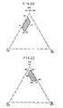
- Embodiments 1 to 4 From the description of Embodiments 1 to 4, it will be seen that, in the recording medium made of a quadruple alloy of Te-O-Ge-Au system, a sufficiently high erasing speed and a sufficiently high recording sensitivity are obtainable when the composition ratio of 0 to the whole system is selected to be, for example, 20 at%, provided that the composition ratio of Te, Ge and Au is selected to fall within the hatched region defined by points A,B,C and D in Fig. 10.
- Evaluation compositions were formed by a composition control such that the composition ratio of Te, Ge and Au becomes 65:10:25. Using this ternary alloy of Te 65 Ge 10 Au 25' recording medium samples were prepared by varying the ratio between this ternary system and 0. The samples thus obtained were placed in a thermo-hygrostate of 40°C and 90 RH% for about 1 month and the change in the optical transmittance was measured at 830 nm wavelength. The result of the measurement is shown in Fig. lla.
- Fig. lla shows that the transmittance is not changed substantially although a slight change is observed in the beginning period, provided that the O composition ratio is 10% or greater.
- the oxygen in the film exists in the form of oxides such as Te0 2 and Ge0 2 , or a composite oxide of such oxides, through bonding to Te or Ge.
- the oxygen is dispersed in such a form as to finely divide the fine grains such as Te, Te-Au, Te-Ge and Te-Ge-Au such as to suppress the crystallization and oxidation of these grains, thus ensuring a high moisture-proof property.
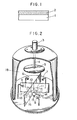
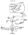
- Fig. 12 shows an optical disk in accordance with the invention and an optical system of an evaluation system.
- the disk has a substrate 29 made of a PMMA resin having a thickness of 1.2 mm and a diameter of 30 200 mm.
- An optical guide track/of 700 A deep and 0.65 ⁇ m wide is formed on the disk concentrically.
- the guide 0 track is covered with an SiO 2 protective film of 1000 A thick formed by evaporation,
- a recording layer 31 of about 900 A thick and having a composition consisting of Te 52 D 20 Ge 8 Au 20 is formed on the protective layer by evaporation.
- the recording layer 31 in turn is covered with an Si0 2 protective film of 1000 A thick formed by evaporation.
- a layer of PMMA resin material which is the same as the material of the substrate is adhered to by a bond, thus completing the optical disk.
- This optical disk was subjected to a recording and erasing test conducted in accordance with the method which is disclosed in P46, brochure of JAPAN DISPLAY, 1983.
- a laser beam emitted from a laser diode 33 having an oscillation wave length of 830 nm was focussed into a recording laser spot 32 having a circular cross-section of 0.9 ⁇ m.
- a laser beam was emitted from a laser diode having an oscillation wavelength of 780 nm and was converged into a elliptical shaped spot 34 which has a peak half value width of 1 ⁇ m x 10 ⁇ m.
- Two laser spots were disposed in close proximity with each other on the same track by means of a common optical system.
- a test recording and erasing was conducted in an area of 150mm/ ⁇ diameter while rotating the disk at a speed of 1800 rpm (peripheral speed about 12 m/sec).
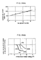
- Fig. 13Aa shows the change in the irradiation time until the start of the darkening by an irradiation with a laser light power of lmW/ um2, while varying the amount of addition of Au in the composition (Te. 0 . 75 Ge 0.1 Sn 0.15 ) 80 O 20 i.e., Te 60 Ge 8 Su 12 O 20 . From this Figure, it will be seen that the irradiation time till the darkening is started can be remarkably shortened by the addition of Au, and that the effect of the addition of Au becomes appreciable when the amount of addition of Au is increased beyond 2%.
- Figs. l3Ba, l3Ca and 13Da show the results of the same test as above, conducted while varying the Au content in the compositions Te 60 Ge 8 In 12 O 20 , Te 60 Ge 8 Bi 12 O 20 and Te 60 Ge 8 Sb 12 O 20 which were obtained by substituting In, Bi and Sb, respectively, for the Sn in the above-explained test.
- a laser beam of a power density of, for example, 1 mW/ ⁇ m 2 was applied for 5 u sec on a recording medium of one of the above-mentioned compositions, e.g., Te 60 Ge 8 Sn 12 O 20 , such as to sufficiently darken the irradiated area, and the darkened area was then irradiated with a laser beam for a fixed period of 50 nsec at varying laser power density.
- the irradiation time till the start of whitening was measured with varying amount of addition of Au, the result of which is shown in Fig. l3Ab.
- Figs. 13Bb, 13Cb and l3Db show the results of the same tests conducted on the material of the system mentioned above, while substituting In, Bi and Sb, respectively, for Sn.
- the irradiation laser beam power density necessary for the start of whitening is increased as a result of the addition of Au but no substantial problem is caused when the amount of addition is not greater than 15% and that the whitening is remarkably suppressed when the amount of addition of Au is 20%, as in the case of the -composition which employs Sn as the additive.
- the materials which are formed by adding additives such as Sn, In, Bi and Sb, respectively, to the composition of Te-Ge-O-Au system satisfy the basic demands for the material of reversible optical information recording medium, and that the erasing speed can be increased by several times without impairing the recording performance as compared with the conventional material by selecting the amount of addition of Au such as to range between 2 and 15%.
- a composition control was conducted to such as to obtain a composition ratio of Te-Ge-M, Au and O of 70:10:20, and various compositions were obtained by varying the the composition ratio of/three elements in Te-Ge-M. Recording medium samples of different compositions were obtained by using these compositions.
- the darkening starting temperature was measured in accordance with the method disclosed in Japanese Patent application No. 70229/ 1984, while varying the composition ratio of Ge. From Fig. l4Aa showing the result of the measurement, it will be seen that the darkening start temperature is increased such as to enhance the thermal stability of the whitened state, as a result of increase in the amount of addition of Ge. These samples were placed in a clean oven of 50°C for the examination of the change in the transmittance.
- the recording sensitivity is somewhat decreased and the reflectivity is also reduced when the amount of addition of Sn reaches 30%, although sufficiently high values of recording or whitening sensitivity are obtained when the amount of addition of Sn is 10% and 20%, respectively.
- the amount of addition of Sn is further increased, the composition ratio of Te as the major element is reduced such as to impair the reversibility of the recording medium. It was confirmed also that, with this material, it is possible to obtain an erasing speed which is several times as high as that of the conventional material, by virtue of addition of Au.
- Figs. l4Bb, l4Cb and 14Db show the results of similar experiments conducted by using In, Bi and Sb, respectively, in place of Sn as the additive element in the above-explained composition.
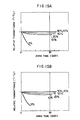
- Figs. 15A to 15D show the results of measurement of the change in the transmittance of the samples when the samples using Sn, In, Bi and Sb, respectively, were left for one month in a thermo-hygrostate of 40°C and 90 RH%. From these Figures, it will be seen that, in all of these sample systems, the transmittance is not changed substantially if the oxygen concentration is 10% or higher although a slight reduction of transmittance is observed in the beginning period, and that the transmittance is not changed at all from the initial value when the oxygen concentration is 30% or higher.
- the oxygen in the film is bonded to Te such as to exist in the form of Te0 2 or bonded to Ge, Sn, In, Bi or Sb such as to exist in the form of oxides Ge0 2 , Sn0 2 , In 2 0 31 Bi 2 0 3 or Sb203, or in the form of composite oxides thereof.
- Te and oxygen co-exist in such a manner that the oxides divide the Te-system alloy.
- An excessive increase in the O content reduces the heat conductivity of the system and tends to permit accumulation of heat when irradiated with a beam, often resulting in a breakdown of the film during repetitional recording and erasing. It was confirmed, however, that this problem can be overcome when the O content is less than 40%.
- the composition ratio Au/Se is one of the important factors which is to be limited. It was found that, in order to obtain sufficient darkening and whitening properties, the Au/Se ratio should range between 0.5 and 5.
- the function of O in the recording film of TeOx system i.e., the function of Te0 2
- Te0 2 The function of O in the recording film of TeOx system, i.e., the function of Te0 2 , is considered to reside in the prevention of growth of fine Te crystal grains at normal temperature level, as well as prevention of oxidation of Te under the presence of steam. It was confirmed that, in the recording film of the invention containing Se, the 0 concentration should be at least 10 at%, from the view point of stability.
- the total content of Te should be large enough to form sufficient amount of Te crystals, besides the Te which is contained in the form of TeO 2 . It was confirmed that, in the recording film in accordance with the invention, the Te give content must be at least 35 at%, in order to/sufficiently high recording sensitivity and sufficiently large change in the optical density of the recording- film.
- the recording film prepared to meet the above- described requirements can show an easy phase change between white and dark states, as well as a large amount of change in the reflectivity, even with a comparatively low level of power of laser beam applied.
- Such a recording film can be considered as being sufficiently practical also from the view point of stability, insofar as it is used at the normal temperature.
- One of the reasons of deterioration of the recorded signal is that the fine Te crystal grains tend to grow into greater size due to a temperature-degradation when the film is left for a long time, i.e., an inevitable darkening of the whitened area.
- Ge is effective in raising the transition start temperature at which the fine Te cyrstal grains start to grow. This effect of addition of Ge is appreciable even when the amount of addition of Ge is as small as 1 at%. On the contrary, when the amount of addition exceeds 10 at%, the transition start temperature rises excessively so that an impractically large power of laser beam is required both for darkening and whitening.
- the darkening sensitivity can be improved without being accompanied by a reduction in the whitening sensitivity, provided that an additive element such as Sn, Sb, Bi or In is added by a small amount, e.g., 5 to 20 at%.
- the additive element such as Sn, In, Bi or Sb when added to the alloy of Te-O-Se-Au system, produces an effect which is different from that produced by the addition of the same additive element such as Sn, In, Bi or Sb to the Te-Ge-Au-0 system alloy explained in the description of preceding embodiments.
- Sn, In, Bi or Sb the same additive element such as Sn, In, Bi or Sb to the Te-Ge-Au-0 system alloy explained in the description of preceding embodiments.
- Se is added for the purpose of increasing the recording sensitivity (whitening sensitivity)
- Au is added for the purpose of increasing the erasing speed (darkening speed), so that it is not necessary to add Sn specifically for such purposes.
- Te0 2 , Te, Se and Au were evaporated from respective sources and deposited onto the surface of pieces of substrate of an acrylic resin of 10 mm long, 2.0 mm wide and 1.2 mm thick, thus forming samples.
- the evaporation was conducted under a vacuum of 1 x 10 -5 Torr and the film 0 thickness was 1200 A.
- the deposition rates from respective sources were varied in order to control the ratio of atom numbers of Te, 0, Se and Au in the film.
- the samples thus formed were subjected to an Auger electron spectroscopy (referred to as "AES", hereinunder) for the purpose of elementary analysis.
- AES Auger electron spectroscopy
- the darkening property and whitening property of these samples were examined by the method explained in connection with Figs. 4 and 5, using the same system as that shown in Fig. 3.
- the measurement of the darkening property was conducted by measuring the time length till the darkening completion, using a laser beam of a power density of about 1 mW/um 2 on the film surface.
- the whitening property was measured by a process having the steps of darkening the sample film by applying a laser beam of a power density of 1 mW/ ⁇ m 2 for 15 p sec, applying short beam pulses of about 50 nsec to the darkened area, and measuring the light power density P 1 required for the whitening.
- Table 1 shows also the result of the moisture proof test.
- the moisture proof test was conducted by keeping the samples for one month in the atmosphere of 40°C and 90 RH% and then measuring the change in the optical transmittance at 830 nm wavelength.
- the samples which showed a transmittance changing ratio of less than 5% are marked at o, while samples which showed a changing ratio exceeding 5% are marked at x. It is considered that the large change in the transmittance is attributable mainly to oxidation of Te.
- an excellent darkening property is defined as being such a property that the darkening is completed and a changing ratio ⁇ R 0 of at least 10% is obtained by irradiation with laser beam of power density of 1 mW/ ⁇ m 2 for 5 usec. It is also assumed that such a whitening property that allows a complete whitening with laser beam pulse of 50 nsec and power density below 10 mW/ ⁇ m 2 , as well as a reflectivity changing ratio ⁇ R 1 of at least 10%, is evaluated as being excellent. As to the moisture proof property, such a property as not to allow substantial moisture- degradation after one month preservation in the atmosphere of 40°C and 90 RH% is evaluated as being excellent.
- the excellent moisture proof property requires also that the condition of 0 ⁇ 10 at%
- the minimum darkening time T 1 of not longer than 1.5 usec and the minimum whitening power density of not greater than 7 mw/ ⁇ m 2 are obtained, thus ensuring best darkening and whitening properties.
- Te-TeO 2 , Se, Au and Ge were simultaneously evaporated from respective sources and deposited onto pieces of substrate made of an acrylic resin, each substrate piece being 10 mm in length, 2.0 mm in width and 1.2 mm in thickness.
- a mixture containing 85 wt% of TeO 2 and 15 wt% of Al was prepared by using a small quantity of alcohol. Then, 25 g of powder of this mixture was placed on a quartz boat and was fired in an electric oven at a temperature of 700°C while circulating N 2 gas, such as to reduce a part of Te0 2 . The fired material was crushed and pressed to form a pellet which is used as the source.
- Embodiment 10 Using these evaporation source materials, the evaporation was conducted to form sample films under the same condition as Embodiment 10.
- the deposition rates from respective sources were adjusted for the purpose of control of the numbers of atoms of Te, 0, Se, Au and Ge.
- the sample films thus formed were subjected to an AES elementary analysis, as well as to measurement of darkening property, whitening property, moisture proof property and heat resistant property.
- the results of the analysis and measurement are shown in Table 2.
- the AES elementary analysis and the measurement of the darkening, whitening and moisture proof properties were carried out in the same way as Embodiment 10.
- the heat resistance property was measured by keeping the sample films for 24 hours at each of temperatures 50°C, 70°C and 90°C.
- the samples which showed no change in the transmittance at all are marked at o, while sample films which showed a change in the transmittance more or less are marked at x.
- the heat resistance property of the recording film can be improved considerably by addition of a small amount of Ge to the film material.
- Te-Te0 2 , Se, Au and Sn were simultaneously evaporated from respective sources and deposited on substrate pieces of an acrylic resin, each piece being 10 mm in length, 2.0 mm in width and 1.2 mm in thickenss, under the same evaporating condition as Embodiment 11.
- the deposition rates from respective sources were varied in order to control the ratio of numbers of atoms of Te, O, Se, Au, Sn (or Sb, Bi, In) in the recording film.
- sample films thus formed were subjected to an AES elementary analysis, as well as to measurement of darkening, whitening and heat-resistant properties, the results of which are shown in Table 3.
- the analysis and measurement were conducted in the same way as Embodiment 11.
- the darkening property can be improved appreciably without being accompanied by substantial degradation in the whitening property, by an addition of small amount of Sn (or Sb, Bi or In) in the recording film.
- Sn or Sb, Bi or In
- a remarkable improvement in the darkening property is achieved without degrading the whitening property at all, when the condition of 5 ⁇ Sn (or Sb, Bi or Zn) ⁇ 20 at% is met.
- Te0 2 , Te, Au and Se were simultaneously evaporated from respective sources and deposited onto an acrylic resin substrate of 1.1 mm thick and 200 mm ⁇ rotating at 150 rpm, thus forming sample optical disk.
- the sample optical disk was subjected to an AES elementary analysis and proved that it had a composition expressed by Te 60 O 20 Se 8 Au 12 .
- the disk was evaluated by an optical system which is designed to effect recording and erasing by employing two different laser diodes. The evaluation system will be explained hereinunder with specific reference to Fig. 25.
- FIG. 25 an optical system for whitening (recording) and reproducing is shown at the left side part of this Figure.
- This optical system has a laser diode for recording 36.
- the beam from this laser diode is changed into a substantially parallel beam 38 by means of a first lens 37, and is shaped by a second lens 39 into a beam having a circular cross-section.
- the beam is again changed into a parallel beam 41 by a third lens 40 and is transmitted by way of a half mirror 42 to a fourth lens 43 which converges the beam into a tiny circular spot 44 of a size of 0.8 p corresponding to the wavelength limit.
- This circular spot produces, when applied to the disk surface 45 rotating at 1800 rpm, the same effect as that produced by beam pulses of a comparatively high light power density and a comparatively short irradiation time. Therefore, if the recording film has been darkened beforehand, it is possible to record the whitened signals on the darkened track by a modulation of the irradiating laser beam.
- the detection of the signals is conducted by a photosensitive diode 49 which receives the light 46 reflected by the disk surface 45 through a half mirror 47 and a lens 48.
- FIG. 25 An optical system for darkening (erasing) purpose is shown at the right side of Fig. 25.
- the laser beam emitted from the laser diode for darkening 50 is changed into a parallel beam 52 by means of a first lens 51, and is converged one-dimensionally by a second lens 53.
- the 55 beam is then changed again into a parallel beam/by means of a lens 54 and is applied through a half mirror 56 and a fourth lens 57 onto the disk surface such as to form a 58 spot / which is elongated in the direction of rotation of the disk.
- This elongated beam spot produces the same effect as that produced by a laser beam spot of a comparatively low light power density and a comparatively long irradiation time. It is, therefore, possible to darken the recording film simultaneously with the whitening by the whitening laser spot in real time.
- the darkening laser beam was shaped into 20 pm x 1 ⁇ m in terms of the half value width, and was used at a power density of about 1 mW/ ⁇ m 2 .
- the whitening laser beam was used at 0.8 ⁇ m ⁇ in terms of half value width and a power density of about 7 mW/um 2 . Recording by whitening and erasing by darkening were conducted by means of these laser beams in the region of 150 mm ⁇ on the disk. As a result, a high C/N ratio exceeding 55 dB was obtained with a single frequency of 5 MHz, and no degradation of C/N ratio was observed even after 100,000 cycles of repetitional recording and erasing.
Landscapes
- Chemical & Material Sciences (AREA)
- Inorganic Chemistry (AREA)
- Optical Record Carriers And Manufacture Thereof (AREA)
- Thermal Transfer Or Thermal Recording In General (AREA)
Applications Claiming Priority (10)
| Application Number | Priority Date | Filing Date | Title |
|---|---|---|---|
| JP123001/84 | 1984-06-15 | ||
| JP59123002A JPS612593A (ja) | 1984-06-15 | 1984-06-15 | 光学情報記録部材 |
| JP123004/84 | 1984-06-15 | ||
| JP123002/84 | 1984-06-15 | ||
| JP123003/84 | 1984-06-15 | ||
| JP59123003A JPS612594A (ja) | 1984-06-15 | 1984-06-15 | 光学情報記録部材 |
| JP59123004A JPS612595A (ja) | 1984-06-15 | 1984-06-15 | 光学情報記録部材 |
| JP59123001A JPS612592A (ja) | 1984-06-15 | 1984-06-15 | 光学情報記録部材 |
| JP127970/84 | 1984-06-21 | ||
| JP59127970A JPS615989A (ja) | 1984-06-21 | 1984-06-21 | 光学情報記録部材 |
Publications (2)
| Publication Number | Publication Date |
|---|---|
| EP0169367A1 true EP0169367A1 (de) | 1986-01-29 |
| EP0169367B1 EP0169367B1 (de) | 1989-11-08 |
Family
ID=27526980
Family Applications (1)
| Application Number | Title | Priority Date | Filing Date |
|---|---|---|---|
| EP19850107452 Expired EP0169367B1 (de) | 1984-06-15 | 1985-06-14 | Auswechselbares optisches Informationsaufzeichnungsmedium |
Country Status (4)
| Country | Link |
|---|---|
| US (1) | US4656079A (de) |
| EP (1) | EP0169367B1 (de) |
| CA (1) | CA1245762A (de) |
| DE (1) | DE3574193D1 (de) |
Cited By (5)
| Publication number | Priority date | Publication date | Assignee | Title |
|---|---|---|---|---|
| EP0217293A1 (de) * | 1985-09-25 | 1987-04-08 | Matsushita Electric Industrial Co., Ltd. | Verwendung von Zusammensetzungen als reversible optische Aufzeichnungsmaterialien |
| EP0239166A1 (de) * | 1986-03-28 | 1987-09-30 | Koninklijke Philips Electronics N.V. | Verfahren zum optischen Aufzeichnen und Auslöschen von Information |
| DE3722100A1 (de) * | 1986-07-04 | 1988-01-14 | Hitachi Ltd | Informationsaufzeichnungsvorrichtung |
| EP0294932A3 (en) * | 1987-06-11 | 1989-10-25 | Asahi Kasei Kogyo Kabushiki Kaisha | A method for recording and erasing information |
| EP0195532B1 (de) * | 1985-02-22 | 1990-05-09 | Asahi Kasei Kogyo Kabushiki Kaisha | Informationsaufzeichnungsmedium |
Families Citing this family (19)
| Publication number | Priority date | Publication date | Assignee | Title |
|---|---|---|---|---|
| JPS61270190A (ja) * | 1985-05-24 | 1986-11-29 | Matsushita Electric Ind Co Ltd | 光学情報記録部材 |
| JPS6284435A (ja) * | 1985-10-08 | 1987-04-17 | Matsushita Electric Ind Co Ltd | 情報記録再生装置 |
| JPS62116183A (ja) * | 1985-11-07 | 1987-05-27 | Canon Inc | 熱記録方法 |
| JP2585520B2 (ja) * | 1985-12-27 | 1997-02-26 | 株式会社日立製作所 | 相変化記録媒体 |
| US4924447A (en) * | 1986-02-07 | 1990-05-08 | Sharp Kabushiki Kaisha | Optical memory device for recording, reproducing or erasing information onto a recording medium, including a recorded region detecting circuit. |
| EP0243976B1 (de) * | 1986-05-02 | 1996-09-04 | Hitachi, Ltd. | Methode zur Aufzeichnung, Wiedergabe und zum Löschen von Informationen und Dünnfilm zur Aufzeichnung von Informationen |
| JP2556682B2 (ja) * | 1986-07-03 | 1996-11-20 | パイオニア株式会社 | 光デイスク装置 |
| US4939717A (en) * | 1986-10-31 | 1990-07-03 | Matsushita Electric Industrial Co., Ltd. | Method and apparatus for erasing and recording information using three power levels |
| KR910003039B1 (ko) * | 1987-01-26 | 1991-05-17 | 가부시기가이샤 히다찌세이사꾸쇼 | 정보의 기록 재생 방법 |
| US4857699A (en) * | 1987-01-30 | 1989-08-15 | Duley Walter W | Means of enhancing laser processing efficiency of metals |
| US4933205A (en) * | 1987-10-09 | 1990-06-12 | Duley Walter W | Laser etching of foam substrate |
| US4972061A (en) * | 1987-12-17 | 1990-11-20 | Duley Walter W | Laser surface treatment |
| NL8800255A (nl) * | 1988-02-03 | 1989-09-01 | Philips Nv | Optische registratiedrager. |
| US5233599A (en) * | 1990-03-14 | 1993-08-03 | Matsushita Electric Industrial Co., Ltd. | Optical disk with a recording layer composed of tellurium, antimony, and germanium |
| RU2151432C1 (ru) * | 1999-12-09 | 2000-06-20 | Лапин Юрий Константинович | Носитель информации оптического запоминающего устройства |
| JP3647848B2 (ja) * | 2002-09-10 | 2005-05-18 | 日立マクセル株式会社 | 情報記録媒体 |
| JP4285452B2 (ja) * | 2005-07-06 | 2009-06-24 | 株式会社日立製作所 | デバイス及びその製造方法 |
| JP5437793B2 (ja) * | 2007-03-30 | 2014-03-12 | パナソニック株式会社 | 情報記録媒体及びその製造方法 |
| JP4497228B2 (ja) * | 2008-05-01 | 2010-07-07 | ソニー株式会社 | 光記録媒体及びその製造方法、並びに、スパッタリング用のターゲット及びその製造方法 |
Citations (1)
| Publication number | Priority date | Publication date | Assignee | Title |
|---|---|---|---|---|
| EP0121426A2 (de) * | 1983-04-01 | 1984-10-10 | Matsushita Electric Industrial Co., Ltd. | Optisches Aufzeichnungsmedium und Verfahren zum optischen Aufnehmen und Löschen auf diesem Medium |
Family Cites Families (6)
| Publication number | Priority date | Publication date | Assignee | Title |
|---|---|---|---|---|
| US3530441A (en) * | 1969-01-15 | 1970-09-22 | Energy Conversion Devices Inc | Method and apparatus for storing and retrieving information |
| US3971874A (en) * | 1973-08-29 | 1976-07-27 | Matsushita Electric Industrial Co., Ltd. | Optical information storage material and method of making it |
| JPS5528530A (en) * | 1978-08-17 | 1980-02-29 | Matsushita Electric Ind Co Ltd | Optical information recording method |
| US4278758A (en) * | 1979-07-06 | 1981-07-14 | Drexler Technology Corporation | Process for making a reflective data storage medium |
| US4461807A (en) * | 1980-07-25 | 1984-07-24 | Asahi Kasei Kogyo Kabushiki Kaisha | Recording material |
| US4587209A (en) * | 1984-03-28 | 1986-05-06 | Matsushita Electric Industrial Co., Ltd. | Optical information recording member comprising Au, TeO2 and Te |
-
1985
- 1985-06-12 US US06/743,801 patent/US4656079A/en not_active Expired - Lifetime
- 1985-06-12 CA CA000483786A patent/CA1245762A/en not_active Expired
- 1985-06-14 DE DE8585107452T patent/DE3574193D1/de not_active Expired
- 1985-06-14 EP EP19850107452 patent/EP0169367B1/de not_active Expired
Patent Citations (1)
| Publication number | Priority date | Publication date | Assignee | Title |
|---|---|---|---|---|
| EP0121426A2 (de) * | 1983-04-01 | 1984-10-10 | Matsushita Electric Industrial Co., Ltd. | Optisches Aufzeichnungsmedium und Verfahren zum optischen Aufnehmen und Löschen auf diesem Medium |
Cited By (9)
| Publication number | Priority date | Publication date | Assignee | Title |
|---|---|---|---|---|
| EP0195532B1 (de) * | 1985-02-22 | 1990-05-09 | Asahi Kasei Kogyo Kabushiki Kaisha | Informationsaufzeichnungsmedium |
| EP0217293A1 (de) * | 1985-09-25 | 1987-04-08 | Matsushita Electric Industrial Co., Ltd. | Verwendung von Zusammensetzungen als reversible optische Aufzeichnungsmaterialien |
| US5278011A (en) * | 1985-09-25 | 1994-01-11 | Matsushita Electric Industrial Co., Ltd. | Reversible optical information-recording medium |
| EP0355865B1 (de) * | 1985-09-25 | 1994-06-01 | Matsushita Electric Industrial Co., Ltd. | Reversibler optischer Informationsaufzeichnungsträger |
| US6268107B1 (en) | 1985-09-25 | 2001-07-31 | Matsushita Electric Industrial Co., Ltd. | Reversible optical information-recording medium |
| USRE42222E1 (en) * | 1985-09-25 | 2011-03-15 | Matsushita Electronic Industrial Co., Ltd. | Reversible optival information-recording medium |
| EP0239166A1 (de) * | 1986-03-28 | 1987-09-30 | Koninklijke Philips Electronics N.V. | Verfahren zum optischen Aufzeichnen und Auslöschen von Information |
| DE3722100A1 (de) * | 1986-07-04 | 1988-01-14 | Hitachi Ltd | Informationsaufzeichnungsvorrichtung |
| EP0294932A3 (en) * | 1987-06-11 | 1989-10-25 | Asahi Kasei Kogyo Kabushiki Kaisha | A method for recording and erasing information |
Also Published As
| Publication number | Publication date |
|---|---|
| US4656079A (en) | 1987-04-07 |
| CA1245762A (en) | 1988-11-29 |
| EP0169367B1 (de) | 1989-11-08 |
| DE3574193D1 (en) | 1989-12-21 |
Similar Documents
| Publication | Publication Date | Title |
|---|---|---|
| EP0169367B1 (de) | Auswechselbares optisches Informationsaufzeichnungsmedium | |
| US5498507A (en) | Optical recording media | |
| US5346740A (en) | Optical information recording medium | |
| US5011723A (en) | Optical information recording medium | |
| EP1293974B1 (de) | Optisches informationsaufzeichnungsmedium | |
| JP3566743B2 (ja) | 光記録媒体 | |
| US5523140A (en) | Optical recording method and medium | |
| US5637371A (en) | Phase change optical recording medium and activation energy determining method | |
| KR19990023556A (ko) | 광학정보 기록매체와 그 제조방법 및 이 매체를 이용한 정보의 기록재생방법 | |
| US5147701A (en) | Information recording medium | |
| EP0163378B1 (de) | Optischer Aufzeichnungsträger | |
| US5294523A (en) | Optical information recording medium | |
| CA1138109A (en) | Recording member | |
| EP1959442A1 (de) | Optisches informationsaufzeichnungsmedium, aufzeichnungs-/wiedergabeverfahren dafür und aufzeichnungs-/wiedergabevorrichtung | |
| JPH0885261A (ja) | 光情報記録媒体およびその製造方法 | |
| JP2908826B2 (ja) | 情報記録媒体 | |
| JP3731372B2 (ja) | 光学的情報記録用媒体並びにその再生方法及び記録方法 | |
| JPH05151619A (ja) | 光情報記録媒体及び記録方法 | |
| JPH0526668B2 (de) | ||
| JPH0530193B2 (de) | ||
| JP2685754B2 (ja) | 情報記録媒体 | |
| JPH0530192B2 (de) | ||
| EP0569664B1 (de) | Optisches Informationsaufzeichnungsmedium und es verwendendes Aufzeichnungsverfahren | |
| JP2712207B2 (ja) | 光学式情報記録媒体 | |
| JP2557407B2 (ja) | 情報記録媒体 |
Legal Events
| Date | Code | Title | Description |
|---|---|---|---|
| PUAI | Public reference made under article 153(3) epc to a published international application that has entered the european phase |
Free format text: ORIGINAL CODE: 0009012 |
|
| AK | Designated contracting states |
Designated state(s): DE FR GB |
|
| 17P | Request for examination filed |
Effective date: 19860619 |
|
| 17Q | First examination report despatched |
Effective date: 19880226 |
|
| GRAA | (expected) grant |
Free format text: ORIGINAL CODE: 0009210 |
|
| AK | Designated contracting states |
Kind code of ref document: B1 Designated state(s): DE FR GB |
|
| REF | Corresponds to: |
Ref document number: 3574193 Country of ref document: DE Date of ref document: 19891221 |
|
| ET | Fr: translation filed | ||
| PLBE | No opposition filed within time limit |
Free format text: ORIGINAL CODE: 0009261 |
|
| STAA | Information on the status of an ep patent application or granted ep patent |
Free format text: STATUS: NO OPPOSITION FILED WITHIN TIME LIMIT |
|
| 26N | No opposition filed | ||
| REG | Reference to a national code |
Ref country code: GB Ref legal event code: 746 Effective date: 19960822 |
|
| REG | Reference to a national code |
Ref country code: GB Ref legal event code: IF02 |
|
| REG | Reference to a national code |
Ref country code: FR Ref legal event code: D6 |
|
| PGFP | Annual fee paid to national office [announced via postgrant information from national office to epo] |
Ref country code: FR Payment date: 20040608 Year of fee payment: 20 |
|
| PGFP | Annual fee paid to national office [announced via postgrant information from national office to epo] |
Ref country code: GB Payment date: 20040609 Year of fee payment: 20 |
|
| PGFP | Annual fee paid to national office [announced via postgrant information from national office to epo] |
Ref country code: DE Payment date: 20040624 Year of fee payment: 20 |
|
| PG25 | Lapsed in a contracting state [announced via postgrant information from national office to epo] |
Ref country code: GB Free format text: LAPSE BECAUSE OF EXPIRATION OF PROTECTION Effective date: 20050613 |
|
| REG | Reference to a national code |
Ref country code: GB Ref legal event code: PE20 |